EP1764515A2 - Système hydraulique pour engins de construction - Google Patents
Système hydraulique pour engins de construction Download PDFInfo
- Publication number
- EP1764515A2 EP1764515A2 EP06018431A EP06018431A EP1764515A2 EP 1764515 A2 EP1764515 A2 EP 1764515A2 EP 06018431 A EP06018431 A EP 06018431A EP 06018431 A EP06018431 A EP 06018431A EP 1764515 A2 EP1764515 A2 EP 1764515A2
- Authority
- EP
- European Patent Office
- Prior art keywords
- pressure
- variable displacement
- main variable
- hydraulic pump
- signal line
- Prior art date
- Legal status (The legal status is an assumption and is not a legal conclusion. Google has not performed a legal analysis and makes no representation as to the accuracy of the status listed.)
- Granted
Links
Images


Classifications
-
- E—FIXED CONSTRUCTIONS
- E02—HYDRAULIC ENGINEERING; FOUNDATIONS; SOIL SHIFTING
- E02F—DREDGING; SOIL-SHIFTING
- E02F9/00—Component parts of dredgers or soil-shifting machines, not restricted to one of the kinds covered by groups E02F3/00 - E02F7/00
- E02F9/20—Drives; Control devices
- E02F9/22—Hydraulic or pneumatic drives
- E02F9/2221—Control of flow rate; Load sensing arrangements
- E02F9/2232—Control of flow rate; Load sensing arrangements using one or more variable displacement pumps
-
- F—MECHANICAL ENGINEERING; LIGHTING; HEATING; WEAPONS; BLASTING
- F15—FLUID-PRESSURE ACTUATORS; HYDRAULICS OR PNEUMATICS IN GENERAL
- F15B—SYSTEMS ACTING BY MEANS OF FLUIDS IN GENERAL; FLUID-PRESSURE ACTUATORS, e.g. SERVOMOTORS; DETAILS OF FLUID-PRESSURE SYSTEMS, NOT OTHERWISE PROVIDED FOR
- F15B21/00—Common features of fluid actuator systems; Fluid-pressure actuator systems or details thereof, not covered by any other group of this subclass
-
- E—FIXED CONSTRUCTIONS
- E02—HYDRAULIC ENGINEERING; FOUNDATIONS; SOIL SHIFTING
- E02F—DREDGING; SOIL-SHIFTING
- E02F9/00—Component parts of dredgers or soil-shifting machines, not restricted to one of the kinds covered by groups E02F3/00 - E02F7/00
- E02F9/20—Drives; Control devices
- E02F9/22—Hydraulic or pneumatic drives
- E02F9/2278—Hydraulic circuits
- E02F9/2296—Systems with a variable displacement pump
-
- F—MECHANICAL ENGINEERING; LIGHTING; HEATING; WEAPONS; BLASTING
- F15—FLUID-PRESSURE ACTUATORS; HYDRAULICS OR PNEUMATICS IN GENERAL
- F15B—SYSTEMS ACTING BY MEANS OF FLUIDS IN GENERAL; FLUID-PRESSURE ACTUATORS, e.g. SERVOMOTORS; DETAILS OF FLUID-PRESSURE SYSTEMS, NOT OTHERWISE PROVIDED FOR
- F15B11/00—Servomotor systems without provision for follow-up action; Circuits therefor
- F15B11/02—Systems essentially incorporating special features for controlling the speed or actuating force of an output member
- F15B11/04—Systems essentially incorporating special features for controlling the speed or actuating force of an output member for controlling the speed
- F15B11/05—Systems essentially incorporating special features for controlling the speed or actuating force of an output member for controlling the speed specially adapted to maintain constant speed, e.g. pressure-compensated, load-responsive
- F15B11/055—Systems essentially incorporating special features for controlling the speed or actuating force of an output member for controlling the speed specially adapted to maintain constant speed, e.g. pressure-compensated, load-responsive by adjusting the pump output or bypass
-
- F—MECHANICAL ENGINEERING; LIGHTING; HEATING; WEAPONS; BLASTING
- F15—FLUID-PRESSURE ACTUATORS; HYDRAULICS OR PNEUMATICS IN GENERAL
- F15B—SYSTEMS ACTING BY MEANS OF FLUIDS IN GENERAL; FLUID-PRESSURE ACTUATORS, e.g. SERVOMOTORS; DETAILS OF FLUID-PRESSURE SYSTEMS, NOT OTHERWISE PROVIDED FOR
- F15B11/00—Servomotor systems without provision for follow-up action; Circuits therefor
- F15B11/16—Servomotor systems without provision for follow-up action; Circuits therefor with two or more servomotors
- F15B11/161—Servomotor systems without provision for follow-up action; Circuits therefor with two or more servomotors with sensing of servomotor demand or load
- F15B11/165—Servomotor systems without provision for follow-up action; Circuits therefor with two or more servomotors with sensing of servomotor demand or load for adjusting the pump output or bypass in response to demand
-
- F—MECHANICAL ENGINEERING; LIGHTING; HEATING; WEAPONS; BLASTING
- F15—FLUID-PRESSURE ACTUATORS; HYDRAULICS OR PNEUMATICS IN GENERAL
- F15B—SYSTEMS ACTING BY MEANS OF FLUIDS IN GENERAL; FLUID-PRESSURE ACTUATORS, e.g. SERVOMOTORS; DETAILS OF FLUID-PRESSURE SYSTEMS, NOT OTHERWISE PROVIDED FOR
- F15B9/00—Servomotors with follow-up action, e.g. obtained by feed-back control, i.e. in which the position of the actuated member conforms with that of the controlling member
- F15B9/02—Servomotors with follow-up action, e.g. obtained by feed-back control, i.e. in which the position of the actuated member conforms with that of the controlling member with servomotors of the reciprocatable or oscillatable type
- F15B9/08—Servomotors with follow-up action, e.g. obtained by feed-back control, i.e. in which the position of the actuated member conforms with that of the controlling member with servomotors of the reciprocatable or oscillatable type controlled by valves affecting the fluid feed or the fluid outlet of the servomotor
- F15B9/09—Servomotors with follow-up action, e.g. obtained by feed-back control, i.e. in which the position of the actuated member conforms with that of the controlling member with servomotors of the reciprocatable or oscillatable type controlled by valves affecting the fluid feed or the fluid outlet of the servomotor with electrical control means
-
- F—MECHANICAL ENGINEERING; LIGHTING; HEATING; WEAPONS; BLASTING
- F15—FLUID-PRESSURE ACTUATORS; HYDRAULICS OR PNEUMATICS IN GENERAL
- F15B—SYSTEMS ACTING BY MEANS OF FLUIDS IN GENERAL; FLUID-PRESSURE ACTUATORS, e.g. SERVOMOTORS; DETAILS OF FLUID-PRESSURE SYSTEMS, NOT OTHERWISE PROVIDED FOR
- F15B2211/00—Circuits for servomotor systems
- F15B2211/20—Fluid pressure source, e.g. accumulator or variable axial piston pump
- F15B2211/205—Systems with pumps
- F15B2211/2053—Type of pump
- F15B2211/20546—Type of pump variable capacity
- F15B2211/20553—Type of pump variable capacity with pilot circuit, e.g. for controlling a swash plate
-
- F—MECHANICAL ENGINEERING; LIGHTING; HEATING; WEAPONS; BLASTING
- F15—FLUID-PRESSURE ACTUATORS; HYDRAULICS OR PNEUMATICS IN GENERAL
- F15B—SYSTEMS ACTING BY MEANS OF FLUIDS IN GENERAL; FLUID-PRESSURE ACTUATORS, e.g. SERVOMOTORS; DETAILS OF FLUID-PRESSURE SYSTEMS, NOT OTHERWISE PROVIDED FOR
- F15B2211/00—Circuits for servomotor systems
- F15B2211/20—Fluid pressure source, e.g. accumulator or variable axial piston pump
- F15B2211/255—Flow control functions
-
- F—MECHANICAL ENGINEERING; LIGHTING; HEATING; WEAPONS; BLASTING
- F15—FLUID-PRESSURE ACTUATORS; HYDRAULICS OR PNEUMATICS IN GENERAL
- F15B—SYSTEMS ACTING BY MEANS OF FLUIDS IN GENERAL; FLUID-PRESSURE ACTUATORS, e.g. SERVOMOTORS; DETAILS OF FLUID-PRESSURE SYSTEMS, NOT OTHERWISE PROVIDED FOR
- F15B2211/00—Circuits for servomotor systems
- F15B2211/30—Directional control
- F15B2211/31—Directional control characterised by the positions of the valve element
- F15B2211/3105—Neutral or centre positions
- F15B2211/3116—Neutral or centre positions the pump port being open in the centre position, e.g. so-called open centre
-
- F—MECHANICAL ENGINEERING; LIGHTING; HEATING; WEAPONS; BLASTING
- F15—FLUID-PRESSURE ACTUATORS; HYDRAULICS OR PNEUMATICS IN GENERAL
- F15B—SYSTEMS ACTING BY MEANS OF FLUIDS IN GENERAL; FLUID-PRESSURE ACTUATORS, e.g. SERVOMOTORS; DETAILS OF FLUID-PRESSURE SYSTEMS, NOT OTHERWISE PROVIDED FOR
- F15B2211/00—Circuits for servomotor systems
- F15B2211/30—Directional control
- F15B2211/32—Directional control characterised by the type of actuation
- F15B2211/329—Directional control characterised by the type of actuation actuated by fluid pressure
Definitions
- the present invention relates to a hydraulic control system for heavy construction equipment, and more particularly to a hydraulic control system that can minimize the flow rate of a hydraulic fluid being discharged from a variable displacement hydraulic pump by using pilot pressure constantly produced by a pilot pump when a switching valve is in a neutral position, and can adjust the flow rate of the hydraulic fluid being discharged from the variable displacement hydraulic pump by using pressure produced by a pressure generator positioned at the most downstream side of a bypass passage if a separate input signal is applied to the pressure generator when the switching valve is operated.
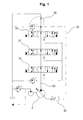
- FIG. 1 shows a hydraulic circuit diagram illustrating the construction of a conventional hydraulic control system with negative control.
- the conventional hydraulic control system includes a main variable displacement hydraulic pump 2, a plurality of actuators (not shown), and a plurality of switching valves 10, 12, and 14 installed in series between the main variable displacement hydraulic pump 2 and a plurality of the actuators.
- a pressure generator 30 is installed at the most downstream side of a bypass passage 20, and pressure produced by the pressure generator 30 is fed to a flow control valve for the hydraulic pump via a pressure signal line 32 to control the flow rate of the hydraulic fluid being discharged from the main variable displacement hydraulic pump 2 in response to the pressure.
- the hydraulic control system has been widely used for its convenient manipulation of a hydraulic excavator. This is because the pressure of the hydraulic fluid fed back to the main variable displacement hydraulic pump 2 from the switching valves 10, 12, and 14 is decreased, or the hydraulic fluid being discharged from the main variable displacement hydraulic pump 2 is supplied to the actuator, with a part of the hydraulic fluid draining away.
- the pressure generated by the pressure generator 30 is fed to the flow control device 40 via the pressure signal line 32 according to the motion of the switching valves 10, 12, and 14.
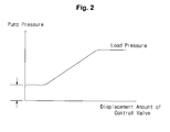
- the switching valves 10, 12, and 14 are in the neutral mode, the pressure in the pressure signal line 32 is raised, and thus the flow rate of the hydraulic fluid being discharged from the main variable displacement hydraulic pump 2 is decreased. If the switching valves 10, 12, and 14 move, the bypass passage 20 is closed. Thus, the pressure in the pressure signal line is lowered, and the flow rate of the hydraulic fluid being discharged from the main variable displacement hydraulic pump 2 is increased. Therefore, it will be understood from the pump pressure diagram shown in FIG. 2 that the pressure of the main variable displacement hydraulic pump 2 is increased by the load applied to the actuator connected to the switching valves 10, 12, and 14.
- the pressure (e.g., of about 30 to 40 bars) is generated corresponding to the pressure in the pressure signal line 32 by the pressure generator 30 in order to minimize the flow rate of the hydraulic fluid being discharged from the main variable displacement hydraulic pump 2.
- the pressure drains away to the tank T via the bypass passage 20, which is not effective in view of energy efficiency.
- another conventional hydraulic control system includes a main variable displacement hydraulic pump 52 connected to a hydraulic pressure supply passage 50, a plurality of actuators (not shown) driven by the hydraulic fluid discharged from the main variable displacement hydraulic pump 52, switching valves 60 and 62 interposed between the main variable displacement hydraulic pump 52 and the actuators, and connected in parallel with the hydraulic pressure supply passage 50, first flow control devices 64 and 66 interposed between the switching valves 60 and 62 and the actuators, a load pressure signal passage 70 for guiding a part of the hydraulic fluid, which is supplied by a switching motion of the switching valves 60 and 62, to a tank T via the first flow control devices 64 and 66, a second flow control device 82 installed on one side of the bypass passage 80 branched from the hydraulic pressure supply passage 50, and operated in an open direction or a closed direction according to the pressure difference between the pressure in the load pressure signal passage 70, pressure of a spring, and pressure in the bypass passage 80 to adjust the flow rate of the hydraulic fluid passing through the bypass passage 80, a pressure generator
- the flow rate of the hydraulic fluid passing through the second flow control device 82 is varied depending upon the load pressure in the load pressure signal passage 70 and the pressure in the bypass passage 80.
- the flow rate of the hydraulic fluid being discharged from the main variable displacement hydraulic pump 52 is controlled by variation of the pressure in the pressure signal line 92.
- the pressure corresponding to the pressure applied in the pressure signal line 92 by the pressure generator 90 is generated in the main variable displacement hydraulic pump 52 so as to minimize the flow rate of the hydraulic fluid being discharged from the main variable displacement hydraulic pump 52.
- the pressure drains away to the tank T via the bypass passage 80, which is still not effective in view of energy efficiency.
- one object of the present invention is to provide a hydraulic control system capable of minimizing the flow rate of a hydraulic fluid being discharged from a main variable displacement hydraulic pump when a switching valve is in a neutral mode, and adjusting the flow rate of the hydraulic fluid being discharged from the main variable displacement hydraulic pump according to the pressure generated in a pressure signal line by a pressure generator when the switching valve is in an operation mode.
- Another object of the present invention is to provide a hydraulic control system capable of minimizing the energy loss that results from drainage of the hydraulic fluid to a tank via a bypass passage when a switching valve is in a neutral mode.
- a hydraulic control system including a main variable displacement hydraulic pump with a hydraulic pressure supply passage extended from one side thereof; a pilot pump for generating a pilot pressure signal; a plurality of actuators driven by a hydraulic fluid discharged from the main variable displacement hydraulic pump; a switching valve interposed between the main variable displacement hydraulic pump and the actuators and connected to the hydraulic pressure supply passage; a first flow control device interposed between the main variable displacement hydraulic pump and the actuators; a load pressure signal passage for guiding a part of the hydraulic fluid, which is supplied by a switching motion of the switching valve, to a tank via the first flow control device; a bypass passage branched from the hydraulic pressure supply passage; a second flow control device installed on one side of the bypass passage and operated in an open direction or a closed direction according to the pressure difference between the pressure in the load pressure signal passage, pressure of a spring, and pressure in the bypass passage to adjust the flow rate of the hydraulic fluid passing through the bypass passage; a pressure generator installed at the most downstream side of the bypass passage;
- a hydraulic control system including a main variable displacement hydraulic pump with a bypass passage extended from one side thereof; a pilot pump for generating a pilot pressure signal; a plurality of actuators driven by a hydraulic fluid discharged from the main variable displacement hydraulic pump; a switching valve interposed between the main variable displacement hydraulic pump and the actuators and connected to the bypass passage; a flow control device for the main variable displacement hydraulic pump installed on one side of the main variable displacement hydraulic pump to control the flow rate of the hydraulic fluid being discharged from the main variable displacement hydraulic pump by adjusting the inclination angle of a swash plate in the main variable displacement hydraulic pump; a first signal line with an inlet side connected to the pilot pump; a second signal line with an outlet side connected to the flow control device; a third signal line branched from the bypass passage; a pressure generator installed on an outlet side of the bypass passage, and bypassing the hydraulic fluid discharged from the main variable displacement hydraulic pump to the tank intact at an initial state and passing the hydraulic fluid through an orifice to generate
- a hydraulic control system including a main variable displacement hydraulic pump with a hydraulic fluid supply passage extended from one side thereof; a pilot pump for generating a pilot pressure signal; a plurality of actuators driven by a hydraulic fluid discharged from the main variable displacement hydraulic pump; a switching valve interposed between the main variable displacement hydraulic pump and the actuators and connected in parallel to the bypass passage; a first flow control device interposed between the switching valve and the actuators; a load pressure signal passage for guiding a part of the hydraulic fluid, which is supplied by a switching motion of the switching valve, to a tank via the first flow control device or a check valve; a bypass passage branched from the hydraulic pressure supply passage; a second flow control device installed on one side of the bypass passage and operated in an open direction or a closed direction according to the pressure difference between the pressure in the load pressure signal passage, pressure of a spring, and pressure in the bypass passage to adjust the flow rate of the hydraulic fluid passing through the bypass passage; a flow control device for the main variable displacement
- a hydraulic control system including a main variable displacement hydraulic pump with a hydraulic fluid supply passage extended from one side thereof; a pilot pump for generating a pilot pressure signal; a plurality of actuators driven by a hydraulic fluid discharged from the main variable displacement hydraulic pump; a switching valve interposed between the main variable displacement hydraulic pump and the actuators and connected in parallel to the bypass passage; a first flow control device interposed between the switching valve and the actuators; a load pressure signal passage for guiding a part of the hydraulic fluid, which is supplied by a switching motion of the switching valve, to a tank via the first flow control device or a check valve; a bypass passage branched from the hydraulic pressure supply passage; a second flow control device installed on one side of the bypass passage and operated in an open direction or a closed direction according to the pressure difference between the pressure in the load pressure signal passage, pressure of a spring, and pressure in the bypass passage to adjust the flow rate of the hydraulic fluid passing through the bypass passage; a flow control device for the main variable displacement
- the input signal is an auto deceleration signal to detect motion of the switching valve.
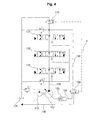
- FIG. 4 is a hydraulic circuit diagram illustrating the construction of a hydraulic control system according to an embodiment of the present invention.
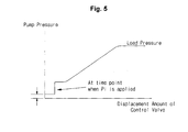
- FIG. 5 is a pump pressure diagram of FIG. 4.
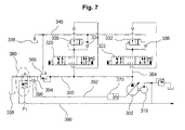
- FIGs. 6 and 7 are hydraulic circuit diagrams illustrating the construction of a hydraulic control system according to alternative embodiments of the present invention.
- the hydraulic control system includes a main variable displacement hydraulic pump 102, a bypass passage 106 extended from the main variable displacement hydraulic pump 102 for draining a hydraulic fluid to a tank 104, a pilot pump 110 for generating a pilot pressure signal, a plurality of actuators (not shown) driven by the hydraulic fluid discharged from the main variable displacement hydraulic pump 102, switching valves 120, 122, and 124 interposed between the main variable displacement hydraulic pump 102 and the actuators, and a flow control device 130 for the main variable displacement hydraulic pump installed on one side of the main variable displacement hydraulic pump 102 to control the flow rate of the hydraulic fluid being discharged from the main variable displacement hydraulic pump 102 by adjusting the inclination angle of a swash plate in the main variable displacement hydraulic pump 102.
- the hydraulic control system includes a first signal line 140 with an inlet side connected to the pilot pump 110, a second signal line 150 with an outlet side connected to the flow control device 130, a third signal line 160 branched from the bypass passage 106, a pressure generator 170 installed on the outlet side of the bypass passage 106, and bypassing the hydraulic fluid discharged from the main variable displacement hydraulic pump 102 to the tank 104 intact at an initial state and passing the hydraulic fluid through an orifice to generate a given level of pressure in the bypass passage 106 when the switching valves are switched by an input signal Pi, and an auxiliary switching valve 180 interposed between the second signal line 150 and the third signal line 160, and communicating the first signal line 140 with the second signal line 150 at an initial state and communicating the second signal line 150 with the third signal line 160 when the switching valves are switched by the input signal Pi.
- the pressure constantly maintained in the pilot pump 110 is applied to the flow control device 130 via the first signal line 140, the auxiliary switching valve 180, and the second signal line 150, as shown in FIG. 4.
- the main variable displacement hydraulic pump 102 is controlled so that the flow rate of the hydraulic fluid being discharged from the main variable displacement hydraulic pump 102 is minimized.
- the pressure generator 170 since the pressure generator 170 is in an initial state, the flow rate, which is controlled to be minimized, of the hydraulic fluid being discharged from the main variable displacement hydraulic pump 102 is returned to the tank 104 via the bypass passage 106. At that time, because the pressure is maintained at a very low level, the energy to be consumed by the main variable displacement hydraulic pump 102 is minimized.
- the auxiliary switching valve 180 is switched so that the first signal line 140 and the second signal line 150 are shut and the second signal line 150 is connected to the third signal line 160.
- the hydraulic fluid is returned to the tank 104 via the bypass passage 106.
- the pressure generator 170 is switched and thus the pressure in the bypass passage 106 is increased, the main variable displacement hydraulic pump 102 is controlled by the pressure applied from the third signal line 160.
- the flow control device 130 increases or decreases the flow rate of the hydraulic fluid being discharged from the main variable displacement hydraulic pump 102 according to the pressure of the third signal line 160.
- the initial pressure generated by the pressure generator 170 installed on the outlet side of the bypass passage 106 to control the flow rate of the hydraulic fluid being discharged from the main variable displacement hydraulic pump 102 can be maintained at a low level, as shown in FIG. 5, so as to improve the loss of the hydraulic fluid returned to the tank 104 via the bypass passage 106. Consequently, there is an advantage of minimizing the energy to be consumed by the main variable displacement hydraulic pump 102 when the switching valves 120, 122, and 124 are in the neutral mode.
- a hydraulic control system includes a main variable displacement hydraulic pump 202, a hydraulic pressure supply passage 204 extended from the main variable displacement hydraulic pump 202, a pilot pump 210 for generating a pilot pressure signal, a plurality of actuators (not shown) driven by the hydraulic fluid discharged from the main variable displacement hydraulic pump 202, switching valves 220 and 222 interposed between the main variable displacement hydraulic pump 202 and the actuators and connected in parallel with the hydraulic pressure supply passage 204, first flow control devices 230 and 232 interposed between the main variable displacement hydraulic pump 202 and the actuators, a load pressure signal passage 240 for guiding a part of the hydraulic fluid, which is supplied by a switching motion of the switching valves 220 and 222, to a tank 238 via the first flow control devices 230 and 232 or check valves 234 and 236, a bypass passage 250 branched from the hydraulic pressure supply passage 204, a second flow control device 260 installed on one side of the bypass passage 250 and operated in
- the hydraulic control system also includes a fourth signal line 290 having an inlet side connected to the pilot pump 210 and an outlet side connected to the pressure generator 280, and a fifth signal line 292 having an inlet side connected to the pressure generator 280 and an outlet side connected to the flow control device 270.
- the bypass passage 250 is connected to one inlet port of the pressure generator 280, and the tank 238 is connected to one outlet port.
- the fourth signal line 290 is connected to the other inlet port, and the fifth signal line 292 is connected to the other outlet port.
- the tank 238 is communicated with the bypass passage 250, and the fourth signal line 290 is communicated with the fifth signal line 292.
- the fourth signal line 290 is disconnected from the fifth signal line 292, and the bypass passage 250 is communicated with the fifth signal line 292.
- the pressure constantly maintained in the pilot pump 210 is applied to the flow control device 270 via the fourth signal line 290, the pressure generator 280, and the fifth signal line 292, as shown in FIG. 6.
- the main variable displacement hydraulic pump 202 is controlled so that the flow rate of the hydraulic fluid being discharged from the main variable displacement hydraulic pump 202 is minimized.
- the hydraulic fluid is returned to the tank 238 via the bypass passage 250 and the pressure generator 280.
- the main variable displacement hydraulic pump 202 is controlled by the pressure applied from the fifth signal line 292.
- the flow control device 270 increases or decreases the flow rate of the hydraulic fluid being discharged from the main variable displacement hydraulic pump 202 according to the pressure of the fifth signal line 292.
- a hydraulic control system includes a main variable displacement hydraulic pump 302, a hydraulic pressure supply passage 304 extended from the main variable displacement hydraulic pump 302, a pilot pump 310 for generating a pilot pressure signal, a plurality of actuators (not shown) driven by the hydraulic fluid discharged from the main variable displacement hydraulic pump 302, switching valves 320 and 322 interposed between the main variable displacement hydraulic pump 302 and the actuators and connected in parallel with the hydraulic pressure supply passage 304, first flow control devices 330 and 332 interposed between the main variable displacement hydraulic pump 302 and the actuators, a load pressure signal passage 340 for guiding a part of the hydraulic fluid, which is supplied by a switching motion of the switching valves 320 and 322, to a tank 338 via the first flow control devices 330 and 332 or check valves 334 and 336, a bypass passage 350 branched from the hydraulic pressure supply passage 304, a second flow control device 360 installed on one side of the bypass passage 350 and operated in an open direction or
- the bypass passage 350 is connected to one inlet port of the pressure generator 380, and the tank 338 is connected to one outlet port.
- the sixth signal line 390 is connected to the other inlet port, and the seventh signal line 392 is connected to the other outlet port.
- the tank 338 is communicated with the bypass passage 350, and the sixth signal line 390 is communicated with the seventh signal line 392.
- the sixth signal line 390 is disconnected from the seventh signal line 392, and the bypass passage 350 is communicated with the seventh signal line 392.
- the pressure constantly maintained in the pilot pump 110 is applied to the flow control device 370 via the sixth signal line 390, the pressure generator 380, the shuttle valve 396, and the seventh signal line 392, as shown in FIG. 6.
- the main variable displacement hydraulic pump 302 is controlled so that the flow rate of the hydraulic fluid being discharged from the main variable displacement hydraulic pump 302 is minimized.
- the hydraulic fluid is returned to the tank 338 via the bypass passage 350 and the pressure generator 380.
- the main variable displacement hydraulic pump 302 is controlled by the pressure applied from the seventh signal line 392.
- the flow control device 370 increases or decreases the flow rate of the hydraulic fluid being discharged from the main variable displacement hydraulic pump 302 according to the pressure of the seventh signal line 392.
- the flow rate of the hydraulic fluid discharged from the main variable displacement hydraulic pump is minimized by the pilot pressure constantly generated from the pilot pump. If the motion of the switching valves is detected by the auto deceleration signal in the switched state and additional input signal is applied to the pressure generator, the flow rate of the hydraulic fluid discharged from the main variable displacement hydraulic pump is controlled depending upon the pressure in the downstream side of the bypass passage.
- the present invention has the following effects.
- the flow rate of the hydraulic fluid initially discharged from the main variable displacement hydraulic pump can be minimized by applying the signal pressure, which is generated by the pressure of the pilot pump, to the pressure generator.
Landscapes
- Engineering & Computer Science (AREA)
- General Engineering & Computer Science (AREA)
- Physics & Mathematics (AREA)
- Fluid Mechanics (AREA)
- Mechanical Engineering (AREA)
- Mining & Mineral Resources (AREA)
- Civil Engineering (AREA)
- Structural Engineering (AREA)
- Chemical & Material Sciences (AREA)
- Analytical Chemistry (AREA)
- Fluid-Pressure Circuits (AREA)
- Operation Control Of Excavators (AREA)
Applications Claiming Priority (1)
| Application Number | Priority Date | Filing Date | Title |
|---|---|---|---|
| KR1020050085993A KR100641397B1 (ko) | 2005-09-15 | 2005-09-15 | 유압제어시스템 |
Publications (3)
| Publication Number | Publication Date |
|---|---|
| EP1764515A2 true EP1764515A2 (fr) | 2007-03-21 |
| EP1764515A3 EP1764515A3 (fr) | 2009-11-25 |
| EP1764515B1 EP1764515B1 (fr) | 2012-08-08 |
Family
ID=37496454
Family Applications (1)
| Application Number | Title | Priority Date | Filing Date |
|---|---|---|---|
| EP06018431A Not-in-force EP1764515B1 (fr) | 2005-09-15 | 2006-09-04 | Système hydraulique pour engins de construction |
Country Status (5)
| Country | Link |
|---|---|
| US (1) | US7458211B2 (fr) |
| EP (1) | EP1764515B1 (fr) |
| JP (1) | JP4613151B2 (fr) |
| KR (1) | KR100641397B1 (fr) |
| CN (1) | CN1932170B (fr) |
Cited By (4)
| Publication number | Priority date | Publication date | Assignee | Title |
|---|---|---|---|---|
| EP2381115A4 (fr) * | 2008-12-24 | 2014-04-30 | Doosan Infracore Co Ltd | Contrôleur de pompe hydraulique pour machine de construction |
| EP2589822A4 (fr) * | 2010-06-30 | 2014-05-14 | Volvo Constr Equip Ab | Dispositif de commande pour une pompe hydraulique de machine de construction |
| EP2677180A4 (fr) * | 2011-02-14 | 2018-02-14 | Hitachi Construction Machinery Co., Ltd. | Dispositif d'entraînement hydraulique d'engin de chantier |
| CN112469865A (zh) * | 2018-07-25 | 2021-03-09 | 克拉克设备公司 | 用于动力机械的液压旁通回路 |
Families Citing this family (8)
| Publication number | Priority date | Publication date | Assignee | Title |
|---|---|---|---|---|
| JP5172477B2 (ja) * | 2008-05-30 | 2013-03-27 | カヤバ工業株式会社 | ハイブリッド建設機械の制御装置 |
| JP5015091B2 (ja) * | 2008-08-14 | 2012-08-29 | 日立建機株式会社 | 油圧作業機械のエンジンラグダウン抑制装置 |
| KR100998613B1 (ko) * | 2008-11-06 | 2010-12-07 | 볼보 컨스트럭션 이큅먼트 에이비 | 건설장비용 유압시스템 |
| DE102012009729A1 (de) * | 2012-05-15 | 2013-11-21 | Robert Bosch Gmbh | Druck-Förderstromregler, Verstelleinheit für eine verstellbare hydraulische Verdrängermaschine mit einem Druck- Förderstromregler und Verfahren zum Regeln einer derartigen Verstelleinheit |
| CN106678110A (zh) * | 2015-11-06 | 2017-05-17 | 徐工集团工程机械股份有限公司 | 中位负流量阀、动臂节能控制系统及挖掘机 |
| JP6302601B2 (ja) * | 2015-12-10 | 2018-03-28 | 川崎重工業株式会社 | 油圧駆動システム |
| CN109442071B (zh) * | 2018-12-31 | 2024-04-12 | 波普科技(唐山)有限公司 | 智能周流调压器 |
| CN112178006B (zh) * | 2020-08-21 | 2022-12-09 | 合肥长源液压股份有限公司 | 一种自动换向的液压缸 |
Family Cites Families (20)
| Publication number | Priority date | Publication date | Assignee | Title |
|---|---|---|---|---|
| US4426194A (en) * | 1981-03-06 | 1984-01-17 | Sundstrand Corporation | Viscosity compensating circuits |
| JPH068641B2 (ja) * | 1986-09-30 | 1994-02-02 | 日立建機株式会社 | 油圧回路 |
| JPH02107802A (ja) * | 1988-08-31 | 1990-04-19 | Hitachi Constr Mach Co Ltd | 油圧駆動装置 |
| US5081838A (en) * | 1989-03-28 | 1992-01-21 | Kabushiki Kaisha Kobe Seiko Sho | Hydraulic circuit with variable relief valves |
| WO1992018711A1 (fr) * | 1991-04-15 | 1992-10-29 | Hitachi Construction Machinery Co., Ltd. | Systeme d'entrainement hydraulique dans un engin de chantier |
| KR970000492B1 (ko) * | 1991-05-09 | 1997-01-13 | 오까다 하지메 | 건설기계의 유압구동장치 |
| JPH0657787A (ja) * | 1992-08-06 | 1994-03-01 | Yutani Heavy Ind Ltd | 破砕機の流量制御装置 |
| JPH06159312A (ja) * | 1992-11-16 | 1994-06-07 | Hitachi Constr Mach Co Ltd | 建設機械の油圧駆動装置 |
| JP3434514B2 (ja) * | 1993-03-23 | 2003-08-11 | 日立建機株式会社 | 油圧作業機の油圧駆動装置 |
| JPH07127607A (ja) * | 1993-09-07 | 1995-05-16 | Yutani Heavy Ind Ltd | 作業機械の油圧装置 |
| KR970011608B1 (ko) * | 1994-09-06 | 1997-07-12 | 대우중공업 주식회사 | 건설기계의 선회토르크 제어장치(an apparatus for controlling turning torque in a construction equipment) |
| EP0795690B1 (fr) * | 1995-07-10 | 2001-12-05 | Hitachi Construction Machinery Co., Ltd. | Dispositif hydraulique de commande |
| US6105367A (en) * | 1996-11-15 | 2000-08-22 | Hitachi Construction Machinery Co. Ltd. | Hydraulic drive system |
| JP3517817B2 (ja) * | 1997-02-24 | 2004-04-12 | 新キャタピラー三菱株式会社 | 油圧パイロット回路 |
| JP3689554B2 (ja) * | 1998-03-31 | 2005-08-31 | カヤバ工業株式会社 | 油圧制御回路 |
| JP2000220604A (ja) * | 1999-02-01 | 2000-08-08 | Hitachi Constr Mach Co Ltd | 油圧ポンプの流量制御装置 |
| JP4767440B2 (ja) * | 2001-06-19 | 2011-09-07 | 東芝機械株式会社 | 油圧制御装置 |
| JP4128482B2 (ja) * | 2002-04-30 | 2008-07-30 | 東芝機械株式会社 | 油圧制御システム |
| JP3992612B2 (ja) * | 2002-12-26 | 2007-10-17 | 株式会社クボタ | バックホウの油圧回路構造 |
| JP3980501B2 (ja) * | 2003-03-07 | 2007-09-26 | 日立建機株式会社 | 建設機械の油圧駆動装置 |
-
2005
- 2005-09-15 KR KR1020050085993A patent/KR100641397B1/ko not_active Expired - Fee Related
-
2006
- 2006-08-25 US US11/510,775 patent/US7458211B2/en not_active Expired - Fee Related
- 2006-09-04 EP EP06018431A patent/EP1764515B1/fr not_active Not-in-force
- 2006-09-07 JP JP2006242294A patent/JP4613151B2/ja not_active Expired - Fee Related
- 2006-09-13 CN CN2006101518831A patent/CN1932170B/zh not_active Expired - Fee Related
Non-Patent Citations (1)
| Title |
|---|
| None |
Cited By (6)
| Publication number | Priority date | Publication date | Assignee | Title |
|---|---|---|---|---|
| EP2381115A4 (fr) * | 2008-12-24 | 2014-04-30 | Doosan Infracore Co Ltd | Contrôleur de pompe hydraulique pour machine de construction |
| EP2589822A4 (fr) * | 2010-06-30 | 2014-05-14 | Volvo Constr Equip Ab | Dispositif de commande pour une pompe hydraulique de machine de construction |
| US9309899B2 (en) | 2010-06-30 | 2016-04-12 | Volvo Construction Equipment Ab | Control device for a hydraulic pump of construction machinery |
| EP2677180A4 (fr) * | 2011-02-14 | 2018-02-14 | Hitachi Construction Machinery Co., Ltd. | Dispositif d'entraînement hydraulique d'engin de chantier |
| CN112469865A (zh) * | 2018-07-25 | 2021-03-09 | 克拉克设备公司 | 用于动力机械的液压旁通回路 |
| CN112469865B (zh) * | 2018-07-25 | 2023-01-20 | 克拉克设备公司 | 用于动力机械的液压旁通回路 |
Also Published As
| Publication number | Publication date |
|---|---|
| JP2007078179A (ja) | 2007-03-29 |
| JP4613151B2 (ja) | 2011-01-12 |
| US20070057571A1 (en) | 2007-03-15 |
| CN1932170B (zh) | 2010-10-13 |
| EP1764515A3 (fr) | 2009-11-25 |
| EP1764515B1 (fr) | 2012-08-08 |
| KR100641397B1 (ko) | 2006-11-01 |
| US7458211B2 (en) | 2008-12-02 |
| CN1932170A (zh) | 2007-03-21 |
Similar Documents
| Publication | Publication Date | Title |
|---|---|---|
| EP2341193B1 (fr) | Système hydraulique de type à contrôle négatif | |
| US9890801B2 (en) | Hydraulic drive system for construction machine | |
| US10526767B2 (en) | Construction machine | |
| JPH11218102A (ja) | 圧油供給装置 | |
| US9650232B2 (en) | Hydraulic drive apparatus for work machine | |
| EP1764515B1 (fr) | Système hydraulique pour engins de construction | |
| KR20110100289A (ko) | 중장비의 유압 펌프 제어 장치 | |
| KR102535297B1 (ko) | 유체 회로 | |
| US7614336B2 (en) | Hydraulic system having augmented pressure compensation | |
| US10072396B2 (en) | Working machine control system | |
| US5291821A (en) | Hydraulic circuit for swivel working machine | |
| CN116771741B (zh) | 液压系统 | |
| JP3081968B2 (ja) | ロードセンシングシステムにおけるカットオフキャンセル機構 | |
| US10208457B2 (en) | Working machine control system | |
| EP1764514A2 (fr) | Système hydraulique pour engins de construction | |
| KR100953808B1 (ko) | 굴삭기의 유압펌프 유량제어장치 | |
| JP2021173390A (ja) | 油圧制御回路 | |
| JP3689554B2 (ja) | 油圧制御回路 | |
| JP4703418B2 (ja) | 油圧アクチュエータ用制御回路 | |
| KR20190105800A (ko) | 피크압력 저감용 유압 시스템 | |
| KR20210099510A (ko) | 유체압 시스템 | |
| JPH03221627A (ja) | 土木・建設機械の油圧回路 | |
| JPH04300402A (ja) | 可変容量型油圧ポンプ制御装置 |
Legal Events
| Date | Code | Title | Description |
|---|---|---|---|
| PUAI | Public reference made under article 153(3) epc to a published international application that has entered the european phase |
Free format text: ORIGINAL CODE: 0009012 |
|
| 17P | Request for examination filed |
Effective date: 20060904 |
|
| AK | Designated contracting states |
Kind code of ref document: A2 Designated state(s): AT BE BG CH CY CZ DE DK EE ES FI FR GB GR HU IE IS IT LI LT LU LV MC NL PL PT RO SE SI SK TR |
|
| AX | Request for extension of the european patent |
Extension state: AL BA HR MK YU |
|
| PUAL | Search report despatched |
Free format text: ORIGINAL CODE: 0009013 |
|
| AK | Designated contracting states |
Kind code of ref document: A3 Designated state(s): AT BE BG CH CY CZ DE DK EE ES FI FR GB GR HU IE IS IT LI LT LU LV MC NL PL PT RO SE SI SK TR |
|
| AX | Request for extension of the european patent |
Extension state: AL BA HR MK RS |
|
| 17Q | First examination report despatched |
Effective date: 20100623 |
|
| AKX | Designation fees paid |
Designated state(s): DE FR GB IT |
|
| GRAP | Despatch of communication of intention to grant a patent |
Free format text: ORIGINAL CODE: EPIDOSNIGR1 |
|
| GRAS | Grant fee paid |
Free format text: ORIGINAL CODE: EPIDOSNIGR3 |
|
| GRAA | (expected) grant |
Free format text: ORIGINAL CODE: 0009210 |
|
| AK | Designated contracting states |
Kind code of ref document: B1 Designated state(s): DE FR GB IT |
|
| REG | Reference to a national code |
Ref country code: GB Ref legal event code: FG4D |
|
| REG | Reference to a national code |
Ref country code: DE Ref legal event code: R096 Ref document number: 602006031216 Country of ref document: DE Effective date: 20121011 |
|
| PLBE | No opposition filed within time limit |
Free format text: ORIGINAL CODE: 0009261 |
|
| STAA | Information on the status of an ep patent application or granted ep patent |
Free format text: STATUS: NO OPPOSITION FILED WITHIN TIME LIMIT |
|
| 26N | No opposition filed |
Effective date: 20130510 |
|
| REG | Reference to a national code |
Ref country code: DE Ref legal event code: R097 Ref document number: 602006031216 Country of ref document: DE Effective date: 20130510 |
|
| REG | Reference to a national code |
Ref country code: FR Ref legal event code: PLFP Year of fee payment: 11 |
|
| PGFP | Annual fee paid to national office [announced via postgrant information from national office to epo] |
Ref country code: DE Payment date: 20170221 Year of fee payment: 11 Ref country code: FR Payment date: 20170223 Year of fee payment: 11 |
|
| PGFP | Annual fee paid to national office [announced via postgrant information from national office to epo] |
Ref country code: GB Payment date: 20170222 Year of fee payment: 11 |
|
| PGFP | Annual fee paid to national office [announced via postgrant information from national office to epo] |
Ref country code: IT Payment date: 20170316 Year of fee payment: 11 |
|
| REG | Reference to a national code |
Ref country code: DE Ref legal event code: R119 Ref document number: 602006031216 Country of ref document: DE |
|
| GBPC | Gb: european patent ceased through non-payment of renewal fee |
Effective date: 20170904 |
|
| REG | Reference to a national code |
Ref country code: FR Ref legal event code: ST Effective date: 20180531 |
|
| PG25 | Lapsed in a contracting state [announced via postgrant information from national office to epo] |
Ref country code: GB Free format text: LAPSE BECAUSE OF NON-PAYMENT OF DUE FEES Effective date: 20170904 Ref country code: DE Free format text: LAPSE BECAUSE OF NON-PAYMENT OF DUE FEES Effective date: 20180404 |
|
| PG25 | Lapsed in a contracting state [announced via postgrant information from national office to epo] |
Ref country code: FR Free format text: LAPSE BECAUSE OF NON-PAYMENT OF DUE FEES Effective date: 20171002 Ref country code: IT Free format text: LAPSE BECAUSE OF NON-PAYMENT OF DUE FEES Effective date: 20170904 |