EP1764663B2 - Dispositif de commande pour actionner une barrière telle qu'une porte, une fenêtre ou similaire, et méthode associée - Google Patents
Dispositif de commande pour actionner une barrière telle qu'une porte, une fenêtre ou similaire, et méthode associée Download PDFInfo
- Publication number
- EP1764663B2 EP1764663B2 EP20050425655 EP05425655A EP1764663B2 EP 1764663 B2 EP1764663 B2 EP 1764663B2 EP 20050425655 EP20050425655 EP 20050425655 EP 05425655 A EP05425655 A EP 05425655A EP 1764663 B2 EP1764663 B2 EP 1764663B2
- Authority
- EP
- European Patent Office
- Prior art keywords
- actuator
- actuators
- data
- string
- controller
- Prior art date
- Legal status (The legal status is an assumption and is not a legal conclusion. Google has not performed a legal analysis and makes no representation as to the accuracy of the status listed.)
- Expired - Lifetime
Links
Images

Classifications
-
- G—PHYSICS
- G05—CONTROLLING; REGULATING
- G05B—CONTROL OR REGULATING SYSTEMS IN GENERAL; FUNCTIONAL ELEMENTS OF SUCH SYSTEMS; MONITORING OR TESTING ARRANGEMENTS FOR SUCH SYSTEMS OR ELEMENTS
- G05B19/00—Program-control systems
- G05B19/02—Program-control systems electric
- G05B19/04—Program control other than numerical control, i.e. in sequence controllers or logic controllers
- G05B19/042—Program control other than numerical control, i.e. in sequence controllers or logic controllers using digital processors
- G05B19/0421—Multiprocessor system
-
- E—FIXED CONSTRUCTIONS
- E05—LOCKS; KEYS; WINDOW OR DOOR FITTINGS; SAFES
- E05F—DEVICES FOR MOVING WINGS INTO OPEN OR CLOSED POSITION; CHECKS FOR WINGS; WING FITTINGS NOT OTHERWISE PROVIDED FOR, CONCERNED WITH THE FUNCTIONING OF THE WING
- E05F15/00—Power-operated mechanisms for wings
- E05F15/60—Power-operated mechanisms for wings using electrical actuators
- E05F15/603—Power-operated mechanisms for wings using electrical actuators using rotary electromotors
-
- E—FIXED CONSTRUCTIONS
- E05—LOCKS; KEYS; WINDOW OR DOOR FITTINGS; SAFES
- E05F—DEVICES FOR MOVING WINGS INTO OPEN OR CLOSED POSITION; CHECKS FOR WINGS; WING FITTINGS NOT OTHERWISE PROVIDED FOR, CONCERNED WITH THE FUNCTIONING OF THE WING
- E05F15/00—Power-operated mechanisms for wings
- E05F15/60—Power-operated mechanisms for wings using electrical actuators
- E05F15/603—Power-operated mechanisms for wings using electrical actuators using rotary electromotors
- E05F15/611—Power-operated mechanisms for wings using electrical actuators using rotary electromotors for swinging wings
- E05F15/616—Power-operated mechanisms for wings using electrical actuators using rotary electromotors for swinging wings operated by push-pull mechanisms
- E05F15/619—Power-operated mechanisms for wings using electrical actuators using rotary electromotors for swinging wings operated by push-pull mechanisms using flexible or rigid rack-and-pinion arrangements
-
- E—FIXED CONSTRUCTIONS
- E05—LOCKS; KEYS; WINDOW OR DOOR FITTINGS; SAFES
- E05Y—INDEXING SCHEME ASSOCIATED WITH SUBCLASSES E05D AND E05F, RELATING TO CONSTRUCTION ELEMENTS, ELECTRIC CONTROL, POWER SUPPLY, POWER SIGNAL OR TRANSMISSION, USER INTERFACES, MOUNTING OR COUPLING, DETAILS, ACCESSORIES, AUXILIARY OPERATIONS NOT OTHERWISE PROVIDED FOR, APPLICATION THEREOF
- E05Y2201/00—Constructional elements; Accessories therefor
- E05Y2201/40—Motors; Magnets; Springs; Weights; Accessories therefor
- E05Y2201/43—Motors
- E05Y2201/434—Electromotors; Details thereof
-
- E—FIXED CONSTRUCTIONS
- E05—LOCKS; KEYS; WINDOW OR DOOR FITTINGS; SAFES
- E05Y—INDEXING SCHEME ASSOCIATED WITH SUBCLASSES E05D AND E05F, RELATING TO CONSTRUCTION ELEMENTS, ELECTRIC CONTROL, POWER SUPPLY, POWER SIGNAL OR TRANSMISSION, USER INTERFACES, MOUNTING OR COUPLING, DETAILS, ACCESSORIES, AUXILIARY OPERATIONS NOT OTHERWISE PROVIDED FOR, APPLICATION THEREOF
- E05Y2201/00—Constructional elements; Accessories therefor
- E05Y2201/60—Suspension or transmission members; Accessories therefor
- E05Y2201/622—Suspension or transmission members elements
- E05Y2201/644—Flexible elongated pulling elements
- E05Y2201/656—Chains
-
- E—FIXED CONSTRUCTIONS
- E05—LOCKS; KEYS; WINDOW OR DOOR FITTINGS; SAFES
- E05Y—INDEXING SCHEME ASSOCIATED WITH SUBCLASSES E05D AND E05F, RELATING TO CONSTRUCTION ELEMENTS, ELECTRIC CONTROL, POWER SUPPLY, POWER SIGNAL OR TRANSMISSION, USER INTERFACES, MOUNTING OR COUPLING, DETAILS, ACCESSORIES, AUXILIARY OPERATIONS NOT OTHERWISE PROVIDED FOR, APPLICATION THEREOF
- E05Y2201/00—Constructional elements; Accessories therefor
- E05Y2201/60—Suspension or transmission members; Accessories therefor
- E05Y2201/622—Suspension or transmission members elements
- E05Y2201/71—Toothed gearing
- E05Y2201/722—Racks
- E05Y2201/724—Flexible
-
- E—FIXED CONSTRUCTIONS
- E05—LOCKS; KEYS; WINDOW OR DOOR FITTINGS; SAFES
- E05Y—INDEXING SCHEME ASSOCIATED WITH SUBCLASSES E05D AND E05F, RELATING TO CONSTRUCTION ELEMENTS, ELECTRIC CONTROL, POWER SUPPLY, POWER SIGNAL OR TRANSMISSION, USER INTERFACES, MOUNTING OR COUPLING, DETAILS, ACCESSORIES, AUXILIARY OPERATIONS NOT OTHERWISE PROVIDED FOR, APPLICATION THEREOF
- E05Y2400/00—Electronic control; Electrical power; Power supply; Power or signal transmission; User interfaces
- E05Y2400/10—Electronic control
- E05Y2400/40—Control units therefor
- E05Y2400/41—Control units therefor for multiple motors
-
- E—FIXED CONSTRUCTIONS
- E05—LOCKS; KEYS; WINDOW OR DOOR FITTINGS; SAFES
- E05Y—INDEXING SCHEME ASSOCIATED WITH SUBCLASSES E05D AND E05F, RELATING TO CONSTRUCTION ELEMENTS, ELECTRIC CONTROL, POWER SUPPLY, POWER SIGNAL OR TRANSMISSION, USER INTERFACES, MOUNTING OR COUPLING, DETAILS, ACCESSORIES, AUXILIARY OPERATIONS NOT OTHERWISE PROVIDED FOR, APPLICATION THEREOF
- E05Y2400/00—Electronic control; Electrical power; Power supply; Power or signal transmission; User interfaces
- E05Y2400/61—Power supply
-
- E—FIXED CONSTRUCTIONS
- E05—LOCKS; KEYS; WINDOW OR DOOR FITTINGS; SAFES
- E05Y—INDEXING SCHEME ASSOCIATED WITH SUBCLASSES E05D AND E05F, RELATING TO CONSTRUCTION ELEMENTS, ELECTRIC CONTROL, POWER SUPPLY, POWER SIGNAL OR TRANSMISSION, USER INTERFACES, MOUNTING OR COUPLING, DETAILS, ACCESSORIES, AUXILIARY OPERATIONS NOT OTHERWISE PROVIDED FOR, APPLICATION THEREOF
- E05Y2800/00—Details, accessories and auxiliary operations not otherwise provided for
- E05Y2800/20—Combinations of elements
- E05Y2800/21—Combinations of elements of identical elements, e.g. of identical compression springs
-
- E—FIXED CONSTRUCTIONS
- E05—LOCKS; KEYS; WINDOW OR DOOR FITTINGS; SAFES
- E05Y—INDEXING SCHEME ASSOCIATED WITH SUBCLASSES E05D AND E05F, RELATING TO CONSTRUCTION ELEMENTS, ELECTRIC CONTROL, POWER SUPPLY, POWER SIGNAL OR TRANSMISSION, USER INTERFACES, MOUNTING OR COUPLING, DETAILS, ACCESSORIES, AUXILIARY OPERATIONS NOT OTHERWISE PROVIDED FOR, APPLICATION THEREOF
- E05Y2800/00—Details, accessories and auxiliary operations not otherwise provided for
- E05Y2800/20—Combinations of elements
- E05Y2800/242—Combinations of elements arranged in parallel relationship
-
- E—FIXED CONSTRUCTIONS
- E05—LOCKS; KEYS; WINDOW OR DOOR FITTINGS; SAFES
- E05Y—INDEXING SCHEME ASSOCIATED WITH SUBCLASSES E05D AND E05F, RELATING TO CONSTRUCTION ELEMENTS, ELECTRIC CONTROL, POWER SUPPLY, POWER SIGNAL OR TRANSMISSION, USER INTERFACES, MOUNTING OR COUPLING, DETAILS, ACCESSORIES, AUXILIARY OPERATIONS NOT OTHERWISE PROVIDED FOR, APPLICATION THEREOF
- E05Y2900/00—Application of doors, windows, wings or fittings thereof
- E05Y2900/10—Application of doors, windows, wings or fittings thereof for buildings or parts thereof
- E05Y2900/13—Type of wing
- E05Y2900/132—Doors
-
- E—FIXED CONSTRUCTIONS
- E05—LOCKS; KEYS; WINDOW OR DOOR FITTINGS; SAFES
- E05Y—INDEXING SCHEME ASSOCIATED WITH SUBCLASSES E05D AND E05F, RELATING TO CONSTRUCTION ELEMENTS, ELECTRIC CONTROL, POWER SUPPLY, POWER SIGNAL OR TRANSMISSION, USER INTERFACES, MOUNTING OR COUPLING, DETAILS, ACCESSORIES, AUXILIARY OPERATIONS NOT OTHERWISE PROVIDED FOR, APPLICATION THEREOF
- E05Y2900/00—Application of doors, windows, wings or fittings thereof
- E05Y2900/10—Application of doors, windows, wings or fittings thereof for buildings or parts thereof
- E05Y2900/13—Type of wing
- E05Y2900/148—Windows
-
- G—PHYSICS
- G05—CONTROLLING; REGULATING
- G05B—CONTROL OR REGULATING SYSTEMS IN GENERAL; FUNCTIONAL ELEMENTS OF SUCH SYSTEMS; MONITORING OR TESTING ARRANGEMENTS FOR SUCH SYSTEMS OR ELEMENTS
- G05B2219/00—Program-control systems
- G05B2219/20—Pc systems
- G05B2219/22—Pc multi processor system
- G05B2219/2237—Selection of leader or follower
-
- G—PHYSICS
- G05—CONTROLLING; REGULATING
- G05B—CONTROL OR REGULATING SYSTEMS IN GENERAL; FUNCTIONAL ELEMENTS OF SUCH SYSTEMS; MONITORING OR TESTING ARRANGEMENTS FOR SUCH SYSTEMS OR ELEMENTS
- G05B2219/00—Program-control systems
- G05B2219/20—Pc systems
- G05B2219/23—Pc programming
- G05B2219/23074—Each control unit can control own associated load or as central control
-
- G—PHYSICS
- G05—CONTROLLING; REGULATING
- G05B—CONTROL OR REGULATING SYSTEMS IN GENERAL; FUNCTIONAL ELEMENTS OF SUCH SYSTEMS; MONITORING OR TESTING ARRANGEMENTS FOR SUCH SYSTEMS OR ELEMENTS
- G05B2219/00—Program-control systems
- G05B2219/20—Pc systems
- G05B2219/26—Pc applications
- G05B2219/2628—Door, window
Definitions
- the present invention relates to an actuator, in particular able to co-operate with other actuators, for operating a closing system.
- actuator according to the invention may be used for doors, windows or the like, below reference will be made for the sake of simplicity only to the example of a window.
- actuators Two types of actuator exist for these applications: a chain actuator or linear actuator. In the case of the latter large and aesthetically unattractive actuators are used when, in fact, they should be aesthetically pleasing and functionally efficient. Therefore, normally the first type, which are much smaller, less voluminous and aesthetically acceptable, are preferred.
- One solution uses the pulses generated by a microswitch inside the actuator and connected to the driving member.
- Two cables convey the pulse signal to an external control unit which controls up to three actuators.
- the control unit processes the number of pulses received from each actuator when one of these actuators sends a larger number of pulses than the other ones, the control unit causes stoppage thereof until the other actuators are synchronized.
- Another solution uses an external control unit in order to control the amount of power used by the actuators connected. If the power used by one actuator is greater than a given predefined value, the control unit stops the actuators and paralyses the system. Rather than proper synchronization, this is just a simple way of controlling operation of the machines.
- Another example of a system with an external control system is described in US 4,933,613 .
- a two drive system usable on a road vehicle for operation of a component such as a sliding roof is disclosed in the utility model DE 296 23 428 U .
- the unit has motors and transmissions coupled to actuators.
- Each drive has a microprocessor module and these have interfaces coupled together by a data line, thereby exchanging data between them for a coordinated movement of the actuators.
- Each actuator sends along the line synchronization data, for management of which a coding system is required in order to define a priority for control of the line (this problem arises when a single resource such as a data bus must be shared by several transceivers). It is obvious that as several actuators are connected to the line the system for managing the associated priority conditions becomes more complex.
- the system also activates the actuators only when each of them has received and recognized all the serial numbers of the other co-operating actuators, such that the problem arises that, in very "noisy" environments, complete initialization can never be achieved because of error signals.
- the actuators Once the actuators start to move the window, each of them sends along the line its own synchronization data and receives that of the other actuators. If an actuator finds that its synchronization data indicates a speed greater than that of another actuator, it slows down. Therefore, if the slower actuator is the last to have priority on the line, its information may be processed with a sufficiently long time delay to cause asynchronism between the actuators.
- the main object of the present invention is to provide a method and an associated device for implementing it, for operating closing systems of the type indicated, which does not have some of the disadvantages of the known systems.
- Another object of the invention is to obtain a device for operating closing systems of the type mentioned, which is simple to manufacture and reliable.
- each actuator may be produced structurally in an identical manner, i.e. using the same components.
- the actuator is configured using suitable programming means for operating either individually, or as a controller actuator (Master, actuator controlling the Slaves) or as an actuator controlled by the Master (Slave).
- the configuration is performed in a simple manner for the user for example by means of a selection device comprising switches, dip-switches or jumpers or by means of a remote programming command which the programming means detect by mean of suitable wireless (e.g. radio or infrared) remote transceiver means.
- the selection interface may also have optionally a display for displaying the status of the actuator.
- the status of the actuator set with the selection device is read by the processing means, which advantageously may be a microprocessor, each time the actuator received a movement command from a user.
- the operating functions of the actuator which are coded by the program inside the microprocessor, are therefore modified in real time, by means of a simple selection performed on the selection device or interface.
- the setting of the operative configuration of the actuators i.e. determining who becomes controller (Master) and all the others controlled actuators (Slaves), establishes an operating hierarchy among the plurality of actuators which simultaneously operate on the closing system.
- the communication between Master and Slaves follows a protocol and predetermined timing sequence, except in the case of anomalous system conditions.
- the main advantage of the invention is being able to have actuators which are structurally identical but can be readily configured so as to obtain a control hierarchy. It is possible both to manufacture actuators in a simple, low-cost and standardized manner (also in the event of replacement which does not require the knowledge of serial codes) and to ensure a high level of immunity of the system with regard to malfunctions and stalemate conditions.
- Each Slave actuator operates autonomously when controlling the motor means for the closing system, but does so following an instruction from the Master who in turn receives a response (feedback) from the Salve as to correct execution of the operation. Continuous monitoring by the Master prevents any loss of synchronism by a Slave.
- the actuators 50, 80 comprise processing means 64 connected in a known manner to a motor 66, a communication interface 68 and a configuration selection interface 70. All these components are powered by a power supply circuit 72 which draws power from three external power supply cables 73a, b, c (normally connected to the electrical supply network).
- the three connections 73a, b, c have the function of powering/controlling the actuator.
- One of the three connections acts as a common connection and the connection of one of the other two to the latter generates an opening or closing command.
- the same principle is also applicable to a version of the invention with a low-voltage power supply, for example 24V c.c., where only two wires (not shown) are used. In this case it is sufficient to reverse their polarity in order to reverse the movement of the motor.
- a low-voltage power supply for example 24V c.c.
- the motor 66 is connected to a drive 74 which engages with the chain 60. Owing to the rotation of the motor 66, the chain 60, which is normally wound inside the casing 62, is unwound and pushed outside of the latter, or pulled back inside, being wound up again.
- An encoder (not shown), for detecting directly or indirectly the travel of the chain 60, is for example associated with the motor 66 for resolving the angular position thereof, said data of travel being processed by the means 64.
- the communication interface 68 is connected to the exterior via two wires 75, 76 which must joined to the corresponding wires of one or more other identical actuators for forming a communication line L between all the actuators connected.
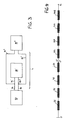
- a star-type network with two centres is thus formed (see Fig. 3 ).
- Three identically designed actuators are indicated by 50, 80' and 80" and the respective wires are indicated by 75, 76; 75', 76' and 75" and 76" and form in groups of three the arms of the two stars.
- the different prime symbols associated with the same reference number indicate that the design of the actuator is identical, but distinguish between different actuator elements.
- the configuration selection interface 70 supplies the processing means 64 with the information which describes the function of the actuator within the line L.
- a user is able - either manually or by means of remote programming (for example via radio if the selection device 70 has remote communication means) - inform the means 64 of the operations which the actuator must perform within the line L.
- the means 64 are for example in the form of a microprocessor, the latter will read the data supplied by the selection device 70 and will consequently adapt the flow and/or the instructions of the program which it is executing in order to perform the particular functions of the actuator in Master mode or in Slave mode (or for individual operation in case the actuator works as an isolated actuator).
- the actuator 50 is the actuator (Master) which controls the other two actuators 80' and 80" (Slaves) via the communication line L. Reference should be made to Fig. 4 .
- each actuator Upon the movement command given by the user, each actuator performs a check to determine whether the actuator must operate as a Master or as a Slave (or neither of the two, in the case where it operates on its own).
- the processing means 64 interrogate the interface 70 and obtain from it configuration data with which they adapt operation of the actuator.
- the actuator If the actuator must operate as a Master, it checks by means of the interface 68 whether the wires 75, 76 are connected to at least one other actuator, which must be a Slave. In the case where a Master detects a second Master along the line, the first Master detects an anomalous situation and stops any activity of the system, while waiting for corrective action on the part of the operator.
- the Master detects a Slave, it starts a procedure to detect the good condition of the data line L, initiating communication of the protocol which terminates with activation of the actuators in the case of a positive outcome: during this step the Master adapts the state of the internal registers of the Slaves to its own state, ensuring consistent interpretation of the future commands and a determined behaviour of the system. If an actuator was set as a Slave, it awaits to receive a data string from a Master via the line L. When the Master initiates the transmission, the Slave replies, resulting in the start of the operating step with communication in controlled actuator mode.
- the Master sends to the first Slave an initialization and identification data string S1 (cf. Fig. 4 ) which contains end-of-travel data, speed data of the chain 60 and alignment data, such as the programmed end-of-travel value, the last blocking code, direction of the movement, etc.
- the Slave receives the alignment string S1 containing the initialization data, extracts it and overwrites on its own data which is therefore ignored.
- the data string S1 like all the subsequent strings, may have a digital or analog format, using the known analog modulation techniques.
- the Slave then replies with a response string S2 indicating its own identification and initialization data.
- the Master receives the string S2 and checks whether the Slave has performed alignment of the registers. If this is not the case, the Master repeats the procedure.
- the Master then sends another identical string S1 to the second Slave which responds with a string S3 and so on for the other Slaves, if there are any.
- the identification and initialization data strings S1, S2 and S3 contain in an identical manner and in the same position the same type of data. Some data is decoded and used by the master, other data is used by the Slave.
- the Master With each user command to move the closing device, the Master sends to the Slaves a start command (contained in a data string) and therefore both the Master actuator and the Slave actuators activate their motor 66 and the chain 60 appropriately.
- Control of the synchronism between the actuators is performed as follows.
- Each Slave sends to the Master a synchronism data string containing in coded form the information relating to the number of revolutions performed by its motor 66 and its reference speed and other information relating to the operating state.
- Each actuator by means of its processing unit 64, processes the information relating to the motor speed, the absorbed current and power supply voltage.
- the motor speed may be calculated - as already mentioned - by means of a position encoder or by means of measurement of the voltage on the motor.
- the Master sends the same data to each Slave.
- the same information is transmitted and received by each actuator whether it be Master or Slave.
- this solution facilitates the design of actuators which as far as possible have the same functional features, increasing the ease of manufacture thereof and reducing the complexity.
- the data string exchanged between Master and Slave also has the same data sequence.
- the Master once it has received the data strings from the Slaves, compares their number of revolutions with its own and, if necessary, corrects the Slave which is out of step. This may occur for example in the following manner ("->" indicates data transmission, see also Fig. 4 ).
- the communication is based on a procedure established by the program contained in the microprocessor and the Master encodes inside the string SO1 the instructions for the Slaves.
- the data structure of the synchronization strings SO1, SO2, SO3 is identical to that of the identification and initialization stings S1, S2, S3.
- the Master classifies and evaluates the deviation in the movement of the Slaves and in its movement by means of different increasing deviation thresholds. Depending on the threshold exceeded by the deviation, the Master sends to the Slaves a command to slow down, setting a slower reference speed which is correspondingly lower the greater the deviation (with a greater deceleration rate). Basically the faster actuator is made to slow down. If the faster actuator is the actual Master, it is realigned without any commands being sent. This means that the Master has a speed and revolutions profile which all the Slaves (and the Master itself) must follow.
- the Master orders all the Slaves to stop, itself also stopping.
- the Master causes slowing down of the actuators so that they are aligned with the one left behind (obviously in relation to the preceding direction of movement).
- the actuator concerned In the case where the closing system encounters an obstacle, the actuator concerned is stopped and transmits a "motor stop" data string. The other actuators which are in listening mode on the transmission channel are stopped immediately. At this point the Master supplies the reference value (reference position) and orders the realignment of the actuators concerned.
- the realignment is possible owing to the transmission by each actuator, to the Master, of the data indicating the travel of the chain 60. Therefore the Master has available, in addition to its own information, that relating to the movement of the Slaves and is able to calculate which of them is furthest behind.
- the actuators are left free from the synchronization so as to allow perfect and safe closing of the leaf; namely after a certain amount of travel, the Master no longer controls the actuators, but only controls them for a few millimetres in the vicinity of the end-of-travel position of the closing system.
- the Slaves are able to respond to the Master only when interrogated, namely following a communication sent to the individual Slave.
- the Master when interrogating the Slave, sends its own information and the control data which it has processed relating to the preceding communication.
- the Slave responds and sends the data necessary for control during the subsequent communication.
- An interrogation procedure of this type is known as "polling".
- An advantageous variant of the invention envisages auto-programming of the actuators which operate in synchronism. Once at least two actuators are connected together as described above, they establish data communication on the line L, recognizing each other. By means of, for example, a factory-set serial number (which the user does not need to know) with a progressively increasing value which results in a different initial time for appropriation of the transmission channel, etc., one of the actuators assumes the Master state and all the others become Slaves. After establishing the roles inside the system, the configuration is saved and therefore the system functions as described above. Following successive activation operations, the Master checks for consistency of the actuator network and, in the event of variation, repeats the initialization procedure.
- Another variant envisages the coexistence in the network L of several Masters which control a subassembly of Slave actuators and exchange between them data so as to maintain correct synchronism and control of the respective series of Slaves.
- a hierarchy as to parity or subordination levels may be established between the Masters, namely there is one Master which controls all the others, this being useful when the number of actuators to be controlled is very high.
- Yet another variant of the invention envisages that the communication between the Master and Slave actuators is performed on an external wireless channel L, for example a radio or infrared channel.
- an external wireless channel L for example a radio or infrared channel.
- remote transmission means not only for programming remotely, but also for transferring data between the actuators.
- the advantage, in this case, of being able to eliminate the wiring associated with a cable communication channel is obvious.
Landscapes
- Physics & Mathematics (AREA)
- General Physics & Mathematics (AREA)
- Engineering & Computer Science (AREA)
- Automation & Control Theory (AREA)
- Power-Operated Mechanisms For Wings (AREA)
- Programmable Controllers (AREA)
- Non-Portable Lighting Devices Or Systems Thereof (AREA)
- Burglar Alarm Systems (AREA)
- Selective Calling Equipment (AREA)
- Liquid Crystal (AREA)
Claims (29)
- Procédé pour actionner un système de fermeture (22) tel que des portes, des fenêtres ou similaire par des actionneurs à déplacements synchronisés, comprenant les étapes consistant à :- prévoir une pluralité d'actionneurs (50, 80) comportant chacun des moyens formant moteur (66, 74) pour déplacer le système de fermeture;- relier les actionneurs au système de fermeture ;- relier les actionneurs au moyen d'un canal de communication de données (L) auquel ils ont accès par l'intermédiaire de leur propre interface d'envoi et de réception (68) et sur laquelle ils échangent des données de synchronisation (SO1; ; SO2 ; SO3), des données d'identification et des données d'initialisation (S1, S2, S3), lesdites données d'identification et d'initialisation étant une chaîne de données d'alignement (S1) et des chaînes de réponse (S2, S3) ;- pourvoir chaque actionneur de moyens de traitement (64) pour gérer individuellement des données sur le canal et commander les moyens formant moteur ;- programmer la condition de fonctionnement de l'actionneur de manière à l'amener à adopter soit une configuration de fonctionnement dans laquelle l'actionneur est le contrôleur (50) et commande au moins l'un des autres actionneurs (80) par l'intermédiaire du canal de données, soit une configuration de fonctionnement dans laquelle l'actionneur est commandé (80) par un autre actionneur-contrôleur (50) par l'intermédiaire du canal de données (L) ;- à la suite d'une commande d'utilisateur de déplacement du système de fermeture, envoyer par l'actionneur-contrôleur (50) audits actionneurs commandés (80) une commande de démarrage qui est suivie d'une activation des moyens formant moteur (66, 74) associés dans la direction appropriée, suivi par- une étape pour vérifier un synchronisme entre les actionneurs où l'actionneur-contrôleur (50) et ledit au moins un actionneur commandé (80) échangent une chaîne de données de synchronisme (SO1, SO2, SO3) contenant des données de synchronisme sous une forme codée, la chaîne de synchronisme (SO1, SO2, SO3) contenant au moins des données concernant le nombre de rotations effectuées par les moyens formant moteur et/ou une vitesse de référence;caractérisé par le fait qu'il comprend une étape supplémentaire à laquelle l'actionneur-contrôleur (50) compare les données de synchronisme contenues dans la chaîne de synchronisme (SO2, SO3) dudit au moins un actionneur commandé (80) avec ses propres données de synchronisme et agit, si nécessaire, de manière à corriger ledit au moins un actionneur commandé (80) qui est hors de synchronisme en évaluant l'écart du déplacement dudit au moins un actionneur commandé (80) au moyen de différents seuils d'écart croissants et, en fonction du seuil dépassé, en envoyant audit au moins un actionneur commandé (80) une commande de ralentissement fixant une vitesse de référence plus faible, qui est d'autant plus faible que l'écart est grand, avec un taux de décélération plus grand.
- Procédé selon la revendication 1, comprenant l'étape supplémentaire de programmation de la condition de fonctionnement de l'actionneur (50, 80) de manière à l'amener à adopter également une configuration de fonctionnement où il fonctionne de manière isolée.
- Procédé selon la revendication 1 ou 2, comprenant une étape d'initialisation où l'actionneur (50, 80) vérifie sa propre condition de fonctionnement et une étape de reconnaissance où, par l'intermédiaire du canal de communication, l'actionneur (50, 80) vérifie la configuration de fonctionnement des autres actionneurs, interrompant son fonctionnement s'il détecte des conditions de fonctionnement qui ne sont pas en harmonie entre elles.
- Procédé selon la revendication 3, comprenant une étape supplémentaire où, au moyen du canal, l'actionneur-contrôleur (50) adapte l'état des registres internes dudit au moins un actionneur commandé (80) à son propre état au moyen de la transmission de la chaîne de données (S1) pour un alignement entre l'actionneur-contrôleur (50) et ledit au moins un actionneur commandé (80) et ledit au moins un actionneur commandé (80) envoie à l'actionneur-contrôleur (50) une chaîne de réponse de données (S2, S3) au moyen de laquelle ce dernier vérifie qu'un alignement correct s'est produit.
- Procédé selon la revendication 4, dans lequel la chaîne de données d'alignement (S1) et la chaîne de réponse (S2, S3) ont la même structure de données.
- Procédé selon l'une quelconque des revendications précédentes, dans lequel la chaîne de synchronisation (SO1, SO2, SO3) a la même structure que la chaîne de données d'alignement (S1) et la chaîne de réponse (S2, S3).
- Procédé selon l'une quelconque des revendications précédentes, dans lequel l'actionneur-contrôleur (50) vérifie s'il est l'actionneur le plus rapide parmi tous ceux-ci et, si nécessaire, se réaligne, en ralentissant.
- Procédé selon l'une quelconque des revendications précédentes, dans lequel, dans le cas d'écarts au-delà d'un seuil maximum, l'actionneur-contrôleur (50) envoie audit au moins un actionneur commandé (80) une commande d'arrêt, s'arrêtant lui-même.
- Procédé selon l'une quelconque des revendications précédentes, dans lequel, dans le cas d'écarts au-delà d'une valeur de seuil maximum, et dans le cas de l'arrêt dudit au moins un actionneur à une position non alignée, l'actionneur-contrôleur (50) envoie audit au moins un actionneur commandé (80) et à lui-même une commande de ralentissement de manière à s'aligner avec l'actionneur qui est le plus en arrière.
- Procédé selon l'une quelconque des revendications précédentes, dans lequel, si un actionneur (50, 80) détecte un obstacle pour le système de fermeture, il s'arrête et envoie une chaîne de données « arrêt de moteur » particulière à laquelle tous les autres actionneurs connectés au canal réagissent en s'arrêtant immédiatement, et dans lequel, après un arrêt collectif des actionneurs, l'actionneur-contrôleur (50) envoie à l'actionneur commandé (80) une position de référence et provoque un réalignement des actionneurs.
- Procédé selon l'une quelconque des revendications précédentes, dans lequel l'actionneur-contrôleur (50) échange des données et/ou des commandes avec un autre actionneur-contrôleur.
- Procédé selon l'une quelconque des revendications précédentes, dans lequel les actionneurs (50, 80) échangent entre eux des données et/ou des commandes avec une séquence de synchronisation fixée.
- Procédé selon l'une quelconque des revendications précédentes, dans lequel les actionneurs (50, 80) échangent entre eux des données et/ou des commandes par l'intermédiaire d'un canal e terne câ lé et/ ou par l'intermédiaire d'un canal de transmission sans fil.
- Procédé selon l'une quelconque des revendications précédentes, dans lequel la condition de fonctionnement des actionneurs (50, 80) est programmée à distance.
- Procédé selon la revendication 14, dans lequel la programmation à distance est effectuée au moyen de moyens d'émission-réception sans fil.
- Actionneurs (50, 80) pour mettre en oeuvre le procédé selon les revendications précédentes, chaque actionneur comprenant :- des moyens formant moteur (66, 74) adaptés pour déplacer le système de fermeture (22) ;- une interface d'envoi et de réception (68) adaptée pour une conne ion à un canal de communication de données (L) e terne au moyen duquel des données peuvent être échangées avec un ou plusieurs actionneurs ;- des moyens de traitement (64) adaptés pour gérer une communication de données sur le canal (L) et commander des moyens formant moteur (66, 74) ;- des moyens adaptés pour programmer la condition de fonctionnement de l'actionneur, capa les de l'amener à adopter soit une configuration de fonctionnement dans laquelle l'actionneur commande au moins un autre actionneur connecté au canal de données, soit une configuration de fonctionnement dans laquelle l'actionneur est commandé (80) par un autre actionneur-contrôleur (50) connecté au canal ;
les moyens de traitement (64) de l'actionneur-contrôleur (50) étant adaptés pour :à la suite d'une commande d'utilisateur de déplacement du système de fermeture, envoyer audits actionneurs commandés (80) une commande de démarrage qui est suivie d'une
activation des moyens formant moteur (66, 74) associés dans la direction appropriée,vérifier le synchronisme entre les actionneurs en échangeant une chaîne de données de synchronisme (SO1, SO2, SO3) avec ledit au moins un actionneur commandé contenant des données de synchronisme sous une forme codée, la chaîne de synchronisme (SO1, SO2, SO3) contenant au moins des données concernant le nom re de rotations effectuées par les moyens formant moteur et/ou une vitesse de référence ;caractérisé en ce que les moyens de traitement (64) de l'actionneur-contrôleur (50) sont adaptés pour :comparer les données de synchronisme contenues dans la chaîne de synchronisme (SO2, SO3) dudit au moins un actionneur commandé (80) avec ses propres données de synchronisme et agir, si nécessaire, de manière à corriger ledit au moins un actionneur commandé (80) qui est hors de synchronisme en évaluant l'écart du déplacement dudit au moins un actionneur commandé (80) au moyen de différents seuils d'écart croissants et, en fonction du seuil dépassé, l'actionneur-contrôleur envoyant audit au moins un actionneur commandé une commande de ralentissement fi ant une vitesse de référence plus fai le, qui est d'autant plus fai le que l'écart est grand, avec un tau de décélération plus grand. - Actionneurs (50, 80) selon la revendication 16, dans lesquels les moyens de traitement sont adaptés pour vérifier la condition de fonctionnement de l'actionneur et pour reconnaître, par l'intermédiaire du canal de communication, une configuration de fonctionnement des autres actionneurs, interrompant son fonctionnement s'il détecte des conditions de fonctionnement qui ne sont pas en harmonie entre elles.
- Actionneurs selon la revendication 16 ou 17, dans lesquels les moyens de traitement de l'actionneur-contrôleur sont adaptés pour adapter l'état des registres internes dudit au moins un actionneur commandé (80) à son propre état au moyen de la transmission d'une chaîne de données (S1, S2, S3) pour un alignement entre l'actionneur-contrôleur (50) et ledit au moins un actionneur commandé (80), tandis que les moyens de traitement dudit au moins un actionneur commandé (80) sont adaptés pour envoyer une chaîne de réponse de données (S2, S3) au moyen de laquelle l'alignement correct est vérifié.
- Actionneurs (50, 80) selon la revendication 18, dans lesquels la chaîne de synchronisation (SO1, SO2, SO3) a la même structure que la chaîne de données d'alignement (S1) et la chaîne de réponse (S2, S3).
- Actionneurs selon l'une des revendications 16 à 19, dans lesquels, dans le cas d'écarts au-delà d'un seuil ma imum, l'actionneur-contrôleur (50) est adapté pour envoyer audit au moins un actionneur commandé (80) une commande d'arrêt, s'arrêtant lui-même.
- Actionneurs selon l'une des revendications 16 à 20, dans lesquels, dans le cas d'écarts au-delà d'un seuil ma imum et dans le cas de l'arrêt dudit au moins un actionneur à une position non alignée, l'actionneur-contrôleur (50) est adapté pour envoyer audit au moins un actionneur commandé (80) et à lui-même une commande de ralentissement de manière à s'aligner avec l'actionneur qui est le plus en arrière.
- Actionneurs (50, 80) selon l'une des revendications 16 à 21, dans lesquels un actionneur est adapté pour s'arrêter et envoyer une chaîne de données « arrêt de moteur » particulière, si un o stacle pour le système de fermeture est détecté, lors de la réception de cette chaîne de données « arrêt de moteur », tous les autres actionneurs connectés au canal sont adaptés pour réagir en s'arrêtant immédiatement, et, après l'arrêt collectif des actionneurs, les moyens de traitement de l'actionneur-contrôleur (50) sont adaptés pour envoyer à l'actionneur commandé (80) une position de référence et pour provoquer un réalignement des actionneurs.
- Actionneurs (50, 80) selon l'une des revendications 16 à 22, dans lesquels les moyens de programmation comprennent un dispositif de sélection (70) pour sélectionner la condition de fonctionnement de l'actionneur.
- Actionneurs (50, 80) selon l'une quelconque des revendications 16 à 23, dans lesquels l'interface de transmission (68) comprend des moyens d'émission-réception sans fil pour former un canal de communication sans fil avec un autre actionneur.
- Actionneurs (50, 80) selon l'une quelconque des revendications 16 à 24, comprenant également un circuit d'alimentation (72) connecté e térieurement à des conducteurs d'alimentation et de commande.
- Actionneurs (50, 80) selon la revendication 25, dans lesquels les conducteurs d'alimentation et de commande sont au nom re de deu et sont connectés à une tension d'alimentation continue.
- Actionneurs (50, 80) selon la revendication 25, dans lesquels les conducteurs d'alimentation et de commande sont au nom re de trois (73a, 73 , 73c), au moins l'un d'entre eu étant connecté au réseau d'alimentation pu lie.
- Actionneurs (50, 80) selon l'une quelconque des revendications 16 à 27, comprenant des moyens d'émission-réception sans fil capa les d'informer à distance les moyens de programmation de la condition de fonctionnement de l'actionneur (50, 80).
- Actionneurs (50, 80) selon l'une quelconque des revendications 16 à 28, dans lesquels les moyens de programmation sont capa les d'amener l'actionneur à adopter également une configuration de fonctionnement où il fonctionne individuellement.
Priority Applications (6)
| Application Number | Priority Date | Filing Date | Title |
|---|---|---|---|
| AT05425655T ATE449367T1 (de) | 2005-09-19 | 2005-09-19 | Antriebsvorrichtung zur ansteuerung von barrieren wie türen, fenster oder dergleichen, und entsprechendes verfahren dazu |
| EP20050425655 EP1764663B2 (fr) | 2005-09-19 | 2005-09-19 | Dispositif de commande pour actionner une barrière telle qu'une porte, une fenêtre ou similaire, et méthode associée |
| DE200560017778 DE602005017778D1 (de) | 2005-09-19 | 2005-09-19 | Antriebsvorrichtung zur Ansteuerung von Barrieren wie Türen, Fenster oder dergleichen, und entsprechendes Verfahren dazu |
| ES05425655T ES2337158T3 (es) | 2005-09-19 | 2005-09-19 | Dispositivo de funcionamiento para accionar una barrera tal como puertas, ventanas o similares, y procedimiento asociado. |
| DK05425655T DK1764663T3 (da) | 2005-09-19 | 2005-09-19 | Drivindretning til at påvirke en barriere såsom døre, vinduer eller lignende, og associeret fremgagnsmåde dertil |
| CN2006101447200A CN1940246B (zh) | 2005-09-19 | 2006-09-19 | 用于致动门、窗等障碍物的驱动设备 |
Applications Claiming Priority (1)
| Application Number | Priority Date | Filing Date | Title |
|---|---|---|---|
| EP20050425655 EP1764663B2 (fr) | 2005-09-19 | 2005-09-19 | Dispositif de commande pour actionner une barrière telle qu'une porte, une fenêtre ou similaire, et méthode associée |
Publications (3)
| Publication Number | Publication Date |
|---|---|
| EP1764663A1 EP1764663A1 (fr) | 2007-03-21 |
| EP1764663B1 EP1764663B1 (fr) | 2009-11-18 |
| EP1764663B2 true EP1764663B2 (fr) | 2013-08-07 |
Family
ID=36168560
Family Applications (1)
| Application Number | Title | Priority Date | Filing Date |
|---|---|---|---|
| EP20050425655 Expired - Lifetime EP1764663B2 (fr) | 2005-09-19 | 2005-09-19 | Dispositif de commande pour actionner une barrière telle qu'une porte, une fenêtre ou similaire, et méthode associée |
Country Status (6)
| Country | Link |
|---|---|
| EP (1) | EP1764663B2 (fr) |
| CN (1) | CN1940246B (fr) |
| AT (1) | ATE449367T1 (fr) |
| DE (1) | DE602005017778D1 (fr) |
| DK (1) | DK1764663T3 (fr) |
| ES (1) | ES2337158T3 (fr) |
Families Citing this family (6)
| Publication number | Priority date | Publication date | Assignee | Title |
|---|---|---|---|---|
| DE102008003580B4 (de) * | 2008-01-09 | 2011-11-17 | Continental Automotive Gmbh | Verfahren und Vorrichtung zum Ermitteln einer Referenzposition eines von einem Elektromotor bewegten Schließteils |
| DE102008035878A1 (de) | 2008-08-01 | 2010-02-11 | Geze Gmbh | Anordnung von Antrieben |
| EP2770385B1 (fr) | 2013-02-22 | 2017-02-01 | Nekos Srl | Procédé permettant un mouvement synchrone d'actionneurs d'un système de fermeture |
| DE112016007202T5 (de) * | 2016-10-04 | 2019-06-13 | Ford Motor Company | Transportwagen mit automatisierter höhenanpassung |
| FR3116621A1 (fr) * | 2020-11-12 | 2022-05-27 | Michel Gelin | Dispositif de commande automatisée de manœuvre de portail à double battant |
| DE102021205141B3 (de) * | 2021-05-20 | 2022-09-01 | Geze Gmbh | Türsystem und Verfahren zum Aktivieren eines zentralen Steuermoduls in einem Türsystem |
Family Cites Families (8)
| Publication number | Priority date | Publication date | Assignee | Title |
|---|---|---|---|---|
| US4933613A (en) | 1988-12-16 | 1990-06-12 | Truth Incorporated | Control for operating a plurality of window operators |
| DE3935173C2 (de) * | 1989-10-21 | 1997-02-06 | Geze Gmbh & Co | Verfahren zur Steuerung eines elektromechanischen Antriebs einer Tür oder dergl. sowie Steuereinrichtung und elektromechanische Antriebseinrichtung |
| DE4041087C2 (de) * | 1990-12-21 | 1995-03-16 | Aumueller Aumatic Gmbh | Verfahren und Vorrichtung zum motorischen Bewegen von großen Flügeln von Lichtkuppeln |
| US5285137A (en) * | 1991-08-30 | 1994-02-08 | Truth Division Of Spx Corporation | User selected controller for a window operator |
| FR2728615A1 (fr) * | 1994-12-23 | 1996-06-28 | Bubendorff Eric | Dispositif pour la commande d'ouverture et de fermeture de moyens d'occultation motorises, tout particulierement de volets roulants |
| DE29623428U1 (de) | 1996-11-28 | 1998-04-23 | Robert Bosch Gmbh, 70469 Stuttgart | Vorrichtung und Steuerung zum koordinierten Betrieb zweier Stellantriebe und zum Datenaustausch |
| DK173956B1 (da) | 1997-02-20 | 2002-03-11 | Vkr Holding As | Betjeningssystem til elektrisk manøvrerbare indretninger og operatorenhed til brug i et sådant system |
| EP0913748A3 (fr) * | 1997-10-31 | 2001-03-21 | Hunter Douglas Industries B.V. | Système de commande de groupe pour les appareils de regulation de la lumière |
-
2005
- 2005-09-19 AT AT05425655T patent/ATE449367T1/de not_active IP Right Cessation
- 2005-09-19 ES ES05425655T patent/ES2337158T3/es not_active Expired - Lifetime
- 2005-09-19 DK DK05425655T patent/DK1764663T3/da active
- 2005-09-19 DE DE200560017778 patent/DE602005017778D1/de not_active Expired - Lifetime
- 2005-09-19 EP EP20050425655 patent/EP1764663B2/fr not_active Expired - Lifetime
-
2006
- 2006-09-19 CN CN2006101447200A patent/CN1940246B/zh not_active Expired - Fee Related
Also Published As
| Publication number | Publication date |
|---|---|
| EP1764663A1 (fr) | 2007-03-21 |
| ES2337158T3 (es) | 2010-04-21 |
| CN1940246B (zh) | 2012-06-27 |
| DE602005017778D1 (de) | 2009-12-31 |
| EP1764663B1 (fr) | 2009-11-18 |
| CN1940246A (zh) | 2007-04-04 |
| ATE449367T1 (de) | 2009-12-15 |
| DK1764663T3 (da) | 2010-04-06 |
Similar Documents
| Publication | Publication Date | Title |
|---|---|---|
| CA2452919C (fr) | Methode, systeme et appareil ameliores d'ouverture de portes | |
| EP2601759B1 (fr) | Système d'automation | |
| US6069465A (en) | Group control system for light regulating devices | |
| US7023162B2 (en) | Automatic gate operator | |
| CA2991042C (fr) | Detection d'obstacle sans fil destinee a etre utilisee avec differents types d'actionneur de barriere | |
| US20130138757A1 (en) | Component addition/substitution method in a home automation wireless system | |
| WO2013020214A1 (fr) | Appareil et système de commande de couvre-fenêtres permettant d'ajuster la quantité de lumière du jour admise | |
| EP1764663B1 (fr) | Dispositif de commande pour actionner une barrière telle qu'une porte, une fenêtre ou similaire, et méthode associée | |
| WO2009074088A1 (fr) | Système anti-coincement de vitre de véhicule automobile basé sur un système de bus lin | |
| US7151351B2 (en) | Method, system and apparatus for opening doors | |
| EP1161609B1 (fr) | Procede et appareil permettant de programmer une carte logique a partir d'une alimentation a commutation | |
| US20170317560A1 (en) | Switching device for switching an electric motor | |
| EP0964974B1 (fr) | Systeme d'operation de dispositifs actionnes electriquement, tels que des portes, des fenetres et analogues, et unite d'entrainement prevue pour un tel systeme | |
| CN108894643B (zh) | 一种通用电动开窗机控制器及其控制方法 | |
| CA2508905C (fr) | Methode et appareil de transfert de parametre d'exploitation d'operateur de barriere mobile | |
| US10472878B2 (en) | System of actuating a door | |
| EP3893445B1 (fr) | Module et dispositif de communication pour des réseaux sans fil | |
| EP4152699B1 (fr) | Détection des erreurs de configuration dans un système de commande de bus | |
| FI4100802T3 (fi) | Seinänsulkemisjärjestelmän konfiguraatio ja vastaava seinänsulkemisjärjestelmä | |
| JP2001040961A (ja) | 電動開閉システム | |
| HK1185644A (en) | Operating method for an electromechanical actuator controlling a movable closure or blind element in a building | |
| PT103655A (pt) | Módulo electrónico para controlo de vidros e tecto de abrir através do barramento controller area network (can) do automóvel | |
| AU2011287273A1 (en) | Wireless network for home automation | |
| JPH06137048A (ja) | 電動開閉装置 |
Legal Events
| Date | Code | Title | Description |
|---|---|---|---|
| PUAI | Public reference made under article 153(3) epc to a published international application that has entered the european phase |
Free format text: ORIGINAL CODE: 0009012 |
|
| AK | Designated contracting states |
Kind code of ref document: A1 Designated state(s): AT BE BG CH CY CZ DE DK EE ES FI FR GB GR HU IE IS IT LI LT LU LV MC NL PL PT RO SE SI SK TR |
|
| AX | Request for extension of the european patent |
Extension state: AL BA HR MK YU |
|
| 17P | Request for examination filed |
Effective date: 20070907 |
|
| AKX | Designation fees paid |
Designated state(s): AT BE BG CH CY CZ DE DK EE ES FI FR GB GR HU IE IS IT LI LT LU LV MC NL PL PT RO SE SI SK TR |
|
| AXX | Extension fees paid |
Extension state: MK Payment date: 20070907 Extension state: HR Payment date: 20070907 Extension state: BA Payment date: 20070907 Extension state: YU Payment date: 20070907 Extension state: AL Payment date: 20070907 |
|
| 17Q | First examination report despatched |
Effective date: 20080118 |
|
| RTI1 | Title (correction) |
Free format text: DRIVING DEVICE FOR ACTUATING A BARRIER SUCH AS DOORS, WINDOWS OR THE LIKE, AND ASSOCIATED METHOD THEREFOR |
|
| GRAP | Despatch of communication of intention to grant a patent |
Free format text: ORIGINAL CODE: EPIDOSNIGR1 |
|
| GRAS | Grant fee paid |
Free format text: ORIGINAL CODE: EPIDOSNIGR3 |
|
| GRAA | (expected) grant |
Free format text: ORIGINAL CODE: 0009210 |
|
| AK | Designated contracting states |
Kind code of ref document: B1 Designated state(s): AT BE BG CH CY CZ DE DK EE ES FI FR GB GR HU IE IS IT LI LT LU LV MC NL PL PT RO SE SI SK TR |
|
| AX | Request for extension of the european patent |
Extension state: AL BA HR MK YU |
|
| REG | Reference to a national code |
Ref country code: GB Ref legal event code: FG4D |
|
| REG | Reference to a national code |
Ref country code: CH Ref legal event code: EP |
|
| REG | Reference to a national code |
Ref country code: IE Ref legal event code: FG4D |
|
| REF | Corresponds to: |
Ref document number: 602005017778 Country of ref document: DE Date of ref document: 20091231 Kind code of ref document: P |
|
| REG | Reference to a national code |
Ref country code: NL Ref legal event code: T3 |
|
| REG | Reference to a national code |
Ref country code: DK Ref legal event code: T3 |
|
| REG | Reference to a national code |
Ref country code: ES Ref legal event code: FG2A Ref document number: 2337158 Country of ref document: ES Kind code of ref document: T3 |
|
| LTIE | Lt: invalidation of european patent or patent extension |
Effective date: 20091118 |
|
| PG25 | Lapsed in a contracting state [announced via postgrant information from national office to epo] |
Ref country code: SE Free format text: LAPSE BECAUSE OF FAILURE TO SUBMIT A TRANSLATION OF THE DESCRIPTION OR TO PAY THE FEE WITHIN THE PRESCRIBED TIME-LIMIT Effective date: 20091118 Ref country code: FI Free format text: LAPSE BECAUSE OF FAILURE TO SUBMIT A TRANSLATION OF THE DESCRIPTION OR TO PAY THE FEE WITHIN THE PRESCRIBED TIME-LIMIT Effective date: 20091118 Ref country code: IS Free format text: LAPSE BECAUSE OF FAILURE TO SUBMIT A TRANSLATION OF THE DESCRIPTION OR TO PAY THE FEE WITHIN THE PRESCRIBED TIME-LIMIT Effective date: 20100318 Ref country code: LT Free format text: LAPSE BECAUSE OF FAILURE TO SUBMIT A TRANSLATION OF THE DESCRIPTION OR TO PAY THE FEE WITHIN THE PRESCRIBED TIME-LIMIT Effective date: 20091118 Ref country code: PT Free format text: LAPSE BECAUSE OF FAILURE TO SUBMIT A TRANSLATION OF THE DESCRIPTION OR TO PAY THE FEE WITHIN THE PRESCRIBED TIME-LIMIT Effective date: 20100318 |
|
| PG25 | Lapsed in a contracting state [announced via postgrant information from national office to epo] |
Ref country code: LV Free format text: LAPSE BECAUSE OF FAILURE TO SUBMIT A TRANSLATION OF THE DESCRIPTION OR TO PAY THE FEE WITHIN THE PRESCRIBED TIME-LIMIT Effective date: 20091118 Ref country code: SI Free format text: LAPSE BECAUSE OF FAILURE TO SUBMIT A TRANSLATION OF THE DESCRIPTION OR TO PAY THE FEE WITHIN THE PRESCRIBED TIME-LIMIT Effective date: 20091118 Ref country code: CY Free format text: LAPSE BECAUSE OF FAILURE TO SUBMIT A TRANSLATION OF THE DESCRIPTION OR TO PAY THE FEE WITHIN THE PRESCRIBED TIME-LIMIT Effective date: 20091118 Ref country code: PL Free format text: LAPSE BECAUSE OF FAILURE TO SUBMIT A TRANSLATION OF THE DESCRIPTION OR TO PAY THE FEE WITHIN THE PRESCRIBED TIME-LIMIT Effective date: 20091118 |
|
| PG25 | Lapsed in a contracting state [announced via postgrant information from national office to epo] |
Ref country code: AT Free format text: LAPSE BECAUSE OF FAILURE TO SUBMIT A TRANSLATION OF THE DESCRIPTION OR TO PAY THE FEE WITHIN THE PRESCRIBED TIME-LIMIT Effective date: 20091118 |
|
| PG25 | Lapsed in a contracting state [announced via postgrant information from national office to epo] |
Ref country code: EE Free format text: LAPSE BECAUSE OF FAILURE TO SUBMIT A TRANSLATION OF THE DESCRIPTION OR TO PAY THE FEE WITHIN THE PRESCRIBED TIME-LIMIT Effective date: 20091118 Ref country code: RO Free format text: LAPSE BECAUSE OF FAILURE TO SUBMIT A TRANSLATION OF THE DESCRIPTION OR TO PAY THE FEE WITHIN THE PRESCRIBED TIME-LIMIT Effective date: 20091118 Ref country code: BG Free format text: LAPSE BECAUSE OF FAILURE TO SUBMIT A TRANSLATION OF THE DESCRIPTION OR TO PAY THE FEE WITHIN THE PRESCRIBED TIME-LIMIT Effective date: 20100218 |
|
| PG25 | Lapsed in a contracting state [announced via postgrant information from national office to epo] |
Ref country code: CZ Free format text: LAPSE BECAUSE OF FAILURE TO SUBMIT A TRANSLATION OF THE DESCRIPTION OR TO PAY THE FEE WITHIN THE PRESCRIBED TIME-LIMIT Effective date: 20091118 Ref country code: SK Free format text: LAPSE BECAUSE OF FAILURE TO SUBMIT A TRANSLATION OF THE DESCRIPTION OR TO PAY THE FEE WITHIN THE PRESCRIBED TIME-LIMIT Effective date: 20091118 |
|
| PLBI | Opposition filed |
Free format text: ORIGINAL CODE: 0009260 |
|
| PLAX | Notice of opposition and request to file observation + time limit sent |
Free format text: ORIGINAL CODE: EPIDOSNOBS2 |
|
| 26 | Opposition filed |
Opponent name: AUMUELLER AUMATIC GMBH Effective date: 20100818 Opponent name: SIEMENS AKTIENGESELLSCHAFT Effective date: 20100818 |
|
| PG25 | Lapsed in a contracting state [announced via postgrant information from national office to epo] |
Ref country code: GR Free format text: LAPSE BECAUSE OF FAILURE TO SUBMIT A TRANSLATION OF THE DESCRIPTION OR TO PAY THE FEE WITHIN THE PRESCRIBED TIME-LIMIT Effective date: 20100219 |
|
| PLAF | Information modified related to communication of a notice of opposition and request to file observations + time limit |
Free format text: ORIGINAL CODE: EPIDOSCOBS2 |
|
| PLAF | Information modified related to communication of a notice of opposition and request to file observations + time limit |
Free format text: ORIGINAL CODE: EPIDOSCOBS2 |
|
| PG25 | Lapsed in a contracting state [announced via postgrant information from national office to epo] |
Ref country code: MC Free format text: LAPSE BECAUSE OF NON-PAYMENT OF DUE FEES Effective date: 20100930 |
|
| REG | Reference to a national code |
Ref country code: CH Ref legal event code: PL |
|
| PLBB | Reply of patent proprietor to notice(s) of opposition received |
Free format text: ORIGINAL CODE: EPIDOSNOBS3 |
|
| PG25 | Lapsed in a contracting state [announced via postgrant information from national office to epo] |
Ref country code: LI Free format text: LAPSE BECAUSE OF NON-PAYMENT OF DUE FEES Effective date: 20100930 Ref country code: IE Free format text: LAPSE BECAUSE OF NON-PAYMENT OF DUE FEES Effective date: 20100919 Ref country code: CH Free format text: LAPSE BECAUSE OF NON-PAYMENT OF DUE FEES Effective date: 20100930 |
|
| PGFP | Annual fee paid to national office [announced via postgrant information from national office to epo] |
Ref country code: DK Payment date: 20110927 Year of fee payment: 7 |
|
| PLBP | Opposition withdrawn |
Free format text: ORIGINAL CODE: 0009264 |
|
| PG25 | Lapsed in a contracting state [announced via postgrant information from national office to epo] |
Ref country code: LU Free format text: LAPSE BECAUSE OF NON-PAYMENT OF DUE FEES Effective date: 20100919 Ref country code: HU Free format text: LAPSE BECAUSE OF FAILURE TO SUBMIT A TRANSLATION OF THE DESCRIPTION OR TO PAY THE FEE WITHIN THE PRESCRIBED TIME-LIMIT Effective date: 20100519 |
|
| PG25 | Lapsed in a contracting state [announced via postgrant information from national office to epo] |
Ref country code: TR Free format text: LAPSE BECAUSE OF FAILURE TO SUBMIT A TRANSLATION OF THE DESCRIPTION OR TO PAY THE FEE WITHIN THE PRESCRIBED TIME-LIMIT Effective date: 20091118 |
|
| PLAB | Opposition data, opponent's data or that of the opponent's representative modified |
Free format text: ORIGINAL CODE: 0009299OPPO |
|
| PGFP | Annual fee paid to national office [announced via postgrant information from national office to epo] |
Ref country code: FR Payment date: 20121001 Year of fee payment: 8 Ref country code: ES Payment date: 20120926 Year of fee payment: 8 |
|
| PGFP | Annual fee paid to national office [announced via postgrant information from national office to epo] |
Ref country code: BE Payment date: 20120925 Year of fee payment: 8 |
|
| PGFP | Annual fee paid to national office [announced via postgrant information from national office to epo] |
Ref country code: NL Payment date: 20120924 Year of fee payment: 8 |
|
| REG | Reference to a national code |
Ref country code: ES Ref legal event code: PC2A Owner name: TOPP SPA Effective date: 20130527 |
|
| REG | Reference to a national code |
Ref country code: NL Ref legal event code: SD Effective date: 20130620 |
|
| PUAH | Patent maintained in amended form |
Free format text: ORIGINAL CODE: 0009272 |
|
| STAA | Information on the status of an ep patent application or granted ep patent |
Free format text: STATUS: PATENT MAINTAINED AS AMENDED |
|
| 27A | Patent maintained in amended form |
Effective date: 20130807 |
|
| AK | Designated contracting states |
Kind code of ref document: B2 Designated state(s): AT BE BG CH CY CZ DE DK EE ES FI FR GB GR HU IE IS IT LI LT LU LV MC NL PL PT RO SE SI SK TR |
|
| AX | Request for extension of the european patent |
Extension state: AL BA HR MK YU |
|
| REG | Reference to a national code |
Ref country code: FR Ref legal event code: TP Owner name: NEKOS SRL, IT Effective date: 20130708 |
|
| REG | Reference to a national code |
Ref country code: DE Ref legal event code: R082 Ref document number: 602005017778 Country of ref document: DE Representative=s name: PRUEFER & PARTNER MBB PATENTANWAELTE RECHTSANW, DE Effective date: 20130704 Ref country code: DE Ref legal event code: R082 Ref document number: 602005017778 Country of ref document: DE Representative=s name: PRUEFER & PARTNER GBR, DE Effective date: 20130704 Ref country code: DE Ref legal event code: R081 Ref document number: 602005017778 Country of ref document: DE Owner name: TOPP SPA, IT Free format text: FORMER OWNER: NEKOS SRL, MASON VICENTINO, IT Effective date: 20130704 |
|
| REG | Reference to a national code |
Ref country code: GB Ref legal event code: 732E Free format text: REGISTERED BETWEEN 20130808 AND 20130814 |
|
| REG | Reference to a national code |
Ref country code: DE Ref legal event code: R102 Ref document number: 602005017778 Country of ref document: DE Effective date: 20130807 |
|
| REG | Reference to a national code |
Ref country code: NL Ref legal event code: VDEP Effective date: 20130807 |
|
| PG25 | Lapsed in a contracting state [announced via postgrant information from national office to epo] |
Ref country code: NL Free format text: LAPSE BECAUSE OF FAILURE TO SUBMIT A TRANSLATION OF THE DESCRIPTION OR TO PAY THE FEE WITHIN THE PRESCRIBED TIME-LIMIT Effective date: 20130807 Ref country code: LV Free format text: LAPSE BECAUSE OF FAILURE TO SUBMIT A TRANSLATION OF THE DESCRIPTION OR TO PAY THE FEE WITHIN THE PRESCRIBED TIME-LIMIT Effective date: 20130807 |
|
| PG25 | Lapsed in a contracting state [announced via postgrant information from national office to epo] |
Ref country code: DK Free format text: LAPSE BECAUSE OF FAILURE TO SUBMIT A TRANSLATION OF THE DESCRIPTION OR TO PAY THE FEE WITHIN THE PRESCRIBED TIME-LIMIT Effective date: 20130807 |
|
| PG25 | Lapsed in a contracting state [announced via postgrant information from national office to epo] |
Ref country code: ES Free format text: LAPSE BECAUSE OF FAILURE TO SUBMIT A TRANSLATION OF THE DESCRIPTION OR TO PAY THE FEE WITHIN THE PRESCRIBED TIME-LIMIT Effective date: 20130807 |
|
| REG | Reference to a national code |
Ref country code: FR Ref legal event code: ST Effective date: 20140530 |
|
| PG25 | Lapsed in a contracting state [announced via postgrant information from national office to epo] |
Ref country code: FR Free format text: LAPSE BECAUSE OF NON-PAYMENT OF DUE FEES Effective date: 20130930 |
|
| PG25 | Lapsed in a contracting state [announced via postgrant information from national office to epo] |
Ref country code: BE Free format text: LAPSE BECAUSE OF NON-PAYMENT OF DUE FEES Effective date: 20130930 |
|
| PGFP | Annual fee paid to national office [announced via postgrant information from national office to epo] |
Ref country code: GB Payment date: 20150904 Year of fee payment: 11 |
|
| PGFP | Annual fee paid to national office [announced via postgrant information from national office to epo] |
Ref country code: DE Payment date: 20150929 Year of fee payment: 11 |
|
| REG | Reference to a national code |
Ref country code: DE Ref legal event code: R119 Ref document number: 602005017778 Country of ref document: DE |
|
| GBPC | Gb: european patent ceased through non-payment of renewal fee |
Effective date: 20160919 |
|
| PG25 | Lapsed in a contracting state [announced via postgrant information from national office to epo] |
Ref country code: DE Free format text: LAPSE BECAUSE OF NON-PAYMENT OF DUE FEES Effective date: 20170401 Ref country code: GB Free format text: LAPSE BECAUSE OF NON-PAYMENT OF DUE FEES Effective date: 20160919 |
|
| PGFP | Annual fee paid to national office [announced via postgrant information from national office to epo] |
Ref country code: IT Payment date: 20240920 Year of fee payment: 20 |