EP1769668A1 - Châssis pivotant d'une tête de récolte pour machines agricoles - Google Patents
Châssis pivotant d'une tête de récolte pour machines agricoles Download PDFInfo
- Publication number
- EP1769668A1 EP1769668A1 EP06018953A EP06018953A EP1769668A1 EP 1769668 A1 EP1769668 A1 EP 1769668A1 EP 06018953 A EP06018953 A EP 06018953A EP 06018953 A EP06018953 A EP 06018953A EP 1769668 A1 EP1769668 A1 EP 1769668A1
- Authority
- EP
- European Patent Office
- Prior art keywords
- frame
- drive train
- attachment according
- header attachment
- machine
- Prior art date
- Legal status (The legal status is an assumption and is not a legal conclusion. Google has not performed a legal analysis and makes no representation as to the accuracy of the status listed.)
- Granted
Links
- 230000008878 coupling Effects 0.000 claims abstract description 33
- 238000010168 coupling process Methods 0.000 claims abstract description 33
- 238000005859 coupling reaction Methods 0.000 claims abstract description 33
- 238000003306 harvesting Methods 0.000 claims abstract description 5
- 235000013399 edible fruits Nutrition 0.000 claims abstract 2
- 230000007246 mechanism Effects 0.000 claims description 7
- 230000003247 decreasing effect Effects 0.000 claims description 3
- 230000005540 biological transmission Effects 0.000 abstract description 6
- 210000000056 organ Anatomy 0.000 description 7
- 241001124569 Lycaenidae Species 0.000 description 2
- 230000009471 action Effects 0.000 description 2
- 230000008901 benefit Effects 0.000 description 2
- 230000008859 change Effects 0.000 description 2
- 238000009434 installation Methods 0.000 description 2
- 238000003971 tillage Methods 0.000 description 2
- 240000008042 Zea mays Species 0.000 description 1
- 235000005824 Zea mays ssp. parviglumis Nutrition 0.000 description 1
- 235000002017 Zea mays subsp mays Nutrition 0.000 description 1
- 230000004913 activation Effects 0.000 description 1
- 238000005452 bending Methods 0.000 description 1
- 239000000969 carrier Substances 0.000 description 1
- 230000006835 compression Effects 0.000 description 1
- 238000007906 compression Methods 0.000 description 1
- 238000010276 construction Methods 0.000 description 1
- 235000005822 corn Nutrition 0.000 description 1
- 230000001419 dependent effect Effects 0.000 description 1
- 238000005516 engineering process Methods 0.000 description 1
- 230000002349 favourable effect Effects 0.000 description 1
- 239000004459 forage Substances 0.000 description 1
- 238000000034 method Methods 0.000 description 1
- 238000003032 molecular docking Methods 0.000 description 1
- 239000002689 soil Substances 0.000 description 1
- 238000011144 upstream manufacturing Methods 0.000 description 1
Images
Classifications
-
- A—HUMAN NECESSITIES
- A01—AGRICULTURE; FORESTRY; ANIMAL HUSBANDRY; HUNTING; TRAPPING; FISHING
- A01D—HARVESTING; MOWING
- A01D41/00—Combines, i.e. harvesters or mowers combined with threshing devices
- A01D41/12—Details of combines
- A01D41/14—Mowing tables
- A01D41/144—Foldable headers
Definitions
- the invention relates to a swing frame of a header unit consisting of at least two, a first and a second machine frame, which are pivotally connected and hinged together, wherein the at least second and folding machine frame comprises at least one drive element, which is the drive side in operative connection with the first machine frame.
- the dumping is intended in particular to reduce the transport width.
- a Verklappungswinkel is provided up to about 180 °, wherein the drive train comprises a propeller shaft, which participates in the folding and thus on the pivoting movement, and wherein the pivotal movement of the drive train (propeller shaft) is controlled via a coupling gear so that they are not decoupled manually must become.
- Agricultural machines with swing frame are known in principle in many ways.
- the EP 0 890 301 A1 describes such an agricultural machine under the term swing frame of a header on agricultural machines.
- Such Emtevorsatzerie are primarily grown on self-propelled combine harvesters or shredders whose working width is well above the permissible transport width.
- Emtevorsatzerie of this kind are either of dismantle the carrier machine or change its position by suitable pivoting or folding mechanisms in such a way that the permissible transport dimensions of such harvesting attachments are not exceeded.
- the attachment described there has pivoting frames, which form the actual machine frame, wherein the outer pivoting frame are folded by about 90 ° in a vertical upward direction to reduce the transport width.
- the work organs are preferably driven by the engine of the work vehicle by means of belting drives for mowing vehicles whose working organs also extend beyond the permissible for road transport width. Described there is a method for pivoting the work vehicle outwardly projecting work organs to about upright axes to the direction of travel, these working organs are after pivoting in your transport position below the raised, the work vehicle upstream, working organ. In this case, the external work organs are pivoted in an approximately horizontal plane by 90 ° to from. On the drive side, the work organs are driven by the engine of the work vehicle by means of belt drive.
- the EP 0 056 118 A1 describes a collapsible and unfoldable implement or tool carrier for agricultural machines with hydraulic pivoting device.
- hinges are articulated on both sides on a carrier main section in hinges on the carrier main section, which can be pivoted about hinge axes pointing in the direction of travel by approximately 180 ° and above one another over the main carrier section to reduce the Transport width can be stored.
- This document describes soil tillage tools and leaves open whether these can also be powered tillage tools.
- the invention provides to design the drive train between the first and the at least second machine frame as a propeller shaft and to arrange them with respect to the hinge axis of the hinged joint, that this is located on the back of the hinge joint.
- the pivoting movement of the propeller shaft is necessarily controlled by a coupling gear, which is articulated to the pivot mechanism and coupled thereto.
- Another inventive advantage is that in the further course of the pivoting movement while the drive train is additionally and automatically disconnected from the at least one drive element of the outer frame, which may serve, for example, for driving work tools, which includes a powertrain interruption.
- the latter protects the drive train against overload at correspondingly large bends of the propeller shaft in case of accidental activation in the folded state of the swing frame and protects him from damage.
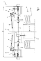
- Fig. 1 shows the machine frame formed as a swing frame 2 of a header 1, e.g. that of a picker for harvesting corn, which in a plan view in working position, i. is shown in unfolded position with the working width 35.
- machine frame is shown as a frame construction, designed as a three-part swing frame 2, wherein this from a first machine frame 3 (middle frame) and second Machine frames 4,4 '(outer frame) exists.
- Middle frame 3 and outer frame 4,4 ' are connected to each other in the hinge joints 18.
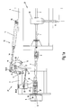
- 1a shows the left half of the machine frame according to Figure 1 in an enlarged view.
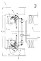
- FIG. 2 shows the transport position of the swing frame 2 of a header attachment 1 according to FIG. 1 with the transport width 36, in which the outer machine frames 4, 4 'are folded inward in the direction of the machine longitudinal center plane 23 by approximately 180 °.
- Emtevorsatzieri 1 of this kind are mainly grown on self-propelled carrier vehicles 24, such as combine harvester or forage harvester before the front wheels 25.
- the drive of the header attachment 1 via a drive train 6 from the engine of the carrier vehicle 24, which branches into further drive trains 7,7 'within a transmission 26, as shown in the example Fig. 1.
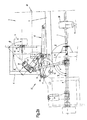
- 2a shows the left half of the machine frame according to Figure 2 in an enlarged view.
- the folding outer frame parts 4,4 'of the swing frame 2 are carriers for driven machine elements, which are not shown in detail for reasons of clarity, but, as shown in the embodiment Fig.1 or Fig.2, by a gear 26 and the engine of the carrier vehicle 24 are driven off.
- the transmission 5 is driven on the input side by a propeller shaft 8, which is connected to the drive train 7.
- the propeller shaft 8 is the continuation of the drive train 7, 7 '.
- the universal joints 9.10 allow angling of the drive train 7, which is continued by the propeller shaft 8.
- a bearing 27 Between the gear housing 5 and the propeller shaft 8 is a bearing 27 and between the bearing 27 and the gear housing fifth There is a clutch release 11, which is engaged in the operating state and thus can transmit the rotational energy.
- the bearing 27 is supported on a rocker 28, which also serves as a bearing bracket, and firmly connected to this.
- the rocker 28 is pivotally hinged in the hinge point 29 on the outer frame 4.
- the hinge axis 30 of the hinge point 29 is obliquely in space, which has a favorable effect on the movement of the pivoting of the propeller shaft 8 during the folding of the machine frame 4.
- the rocker 28 is held by a coupling rod 31 in its intended position or controlled during the folding of this, the coupling rod 31 is struck in the pivot point 32 on the rocker 28.
- the coupling rod 31 is connected to the lever 21, wherein the lever 21 is fixedly connected to a boom 34.
- Boom 34 and lever 21 thus form a firmly interconnected unit, so that when the lever 21 is pivoted, the boom 34 is also pivoted with.
- the lever 21 is connected in the hinge point 17 with the outer frame 4,4 '. At the free end of the lever 21 is the hinge point 16, at the same time the hinge eye 15 of the piston rod 14 is struck. Also in the pivot point 16 a curved coupling 22 is struck, which is supported in the hinge point 19 of the center frame 3.
- the actuator 12 is acted upon by the driver's seat of the driver so with pressure that the piston rod hineinafter into the interior of the cylinder housing 13, so that the outer frame 4,4 'pivoted about the pivot axis of the hinge joint 18.
- the actuation of the pivot drive 12 also causes a pivoting operation of the lever 21, to which the coupling rod 31 is struck in the hinge point 33. At the other end of the coupling rod 31, this is struck in the pivot point 32 on the rocker 28, so that the rocker 28 is pivoted by entrainment of the coupling rod 31 in the hinge point 29 about the hinge axis 30.
- the pivot angle ⁇ is defined by the pivot angle difference, which is set between the virtual end position 40 of the rocker 28, which would then set when the rocker 28 equally covers the full swing angle ⁇ , and the actual end position 41 of the rocker 28 in the fully opened state transport position.
- the rocker 28 undergoes a change of your space coordinates with respect to the middle frame 3 by the folding operation, and on the other hand a rotation about the pivot angle ⁇ relative to the outer frame 4,4 '.
- the pivot angle ⁇ is enforced or controlled by the coupling movement of the coupling rod 31 with the lever 21.
- a particular inventive advantage is that due to this coupling mechanism 37 consisting of the elements middle frame 3, outer frame 4, actuator 12, coupling 22, lever 21, coupling rod 31 and rocker 28, the pivot angle difference ⁇ especially in the interval limits ⁇ / 2 ⁇ ⁇ / 4 may lie.
- At least one of the coupling halves is biased by a compression spring in the axial direction, so that at least one coupling half 38 or 39 in the event that a rotational angle offset the engaged position has occurred, temporarily as long as the other coupling half can escape until it can engage automatically and completely under the action of the spring force when switching on the drive train 7 again.
- the invention is by no means limited exclusively to agricultural harvesters as attachments, but they can in principle also be applied there in agricultural technology, when it comes to coupling pivotable machine frames to drive trains of the kind set forth.
Landscapes
- Life Sciences & Earth Sciences (AREA)
- Environmental Sciences (AREA)
- Agricultural Machines (AREA)
- Harvester Elements (AREA)
- Harvesting Machines For Root Crops (AREA)
Applications Claiming Priority (1)
| Application Number | Priority Date | Filing Date | Title |
|---|---|---|---|
| DE102005046883A DE102005046883A1 (de) | 2005-09-29 | 2005-09-29 | Schwenkrahmen eines Erntevorsatzgerätes für landwirtschaftliche Arbeitsmaschinen |
Publications (2)
| Publication Number | Publication Date |
|---|---|
| EP1769668A1 true EP1769668A1 (fr) | 2007-04-04 |
| EP1769668B1 EP1769668B1 (fr) | 2009-02-11 |
Family
ID=37499710
Family Applications (1)
| Application Number | Title | Priority Date | Filing Date |
|---|---|---|---|
| EP06018953A Active EP1769668B1 (fr) | 2005-09-29 | 2006-09-11 | Tête de récolte avec châssis pivotant pour machines agricoles |
Country Status (3)
| Country | Link |
|---|---|
| EP (1) | EP1769668B1 (fr) |
| AT (1) | ATE422287T1 (fr) |
| DE (2) | DE102005046883A1 (fr) |
Cited By (7)
| Publication number | Priority date | Publication date | Assignee | Title |
|---|---|---|---|---|
| ITBO20110606A1 (it) * | 2011-10-28 | 2013-04-29 | Falc S R L | Macchina trinciatrice |
| US9603306B2 (en) | 2014-07-09 | 2017-03-28 | Cnh Industrial America Llc | Agricultural machine with retaining elements for retaining a header in an elevated position |
| US10143138B2 (en) | 2014-04-30 | 2018-12-04 | Cnh Industrial America Llc | Transport system for a center pivot agricultural machine |
| US10194583B2 (en) | 2013-09-11 | 2019-02-05 | Cnh Industrial America Llc | Hitch swing cylinder mounting point repositioning mechanism |
| AT525423A1 (de) * | 2021-09-08 | 2023-03-15 | Georg Hanslauer | Schneidwerk für oberhalb von Kulturpflanzen abzuschneidendes Unkraut |
| CN117184712A (zh) * | 2023-09-12 | 2023-12-08 | 江苏裕灌现代农业科技有限公司 | 一种双孢蘑菇堆料的隧道进料装置 |
| US20250107490A1 (en) * | 2023-09-28 | 2025-04-03 | Deere & Company | Systems, methods, and apparatuses for folding and articulating an agricultural head |
Families Citing this family (2)
| Publication number | Priority date | Publication date | Assignee | Title |
|---|---|---|---|---|
| US9565800B2 (en) | 2014-09-08 | 2017-02-14 | Cnh Industrial America Llc | Windrow shield control system for a header of an agricultural harvester |
| DE102015206142A1 (de) | 2015-04-07 | 2016-10-13 | Maschinenfabrik Kemper Gmbh & Co. Kg | Erntevorsatz für landwirtschaftliche Erntemaschinen |
Citations (4)
| Publication number | Priority date | Publication date | Assignee | Title |
|---|---|---|---|---|
| DE2026190A1 (de) * | 1969-06-02 | 1970-12-23 | Clayson naamloze vennootschap, Zedelgem (Belgien) | Teilbares Mähbrett für Mähdrescher |
| DE2000478A1 (de) * | 1970-01-07 | 1971-11-18 | Fahr Ag Maschf | Maehdrescher,insbesondere selbstfahrender Maehdrescher |
| DE3605933A1 (de) * | 1986-02-25 | 1987-08-27 | Klemens Kalverkamp | Erntevorsatz einer erntemaschine |
| EP0890301A1 (fr) * | 1997-06-17 | 1999-01-13 | Claas Saulgau Gmbh | Châssis pivotant d'une tête de récolte de machines agricoles pour ramasser et convoyer des céréales |
-
2005
- 2005-09-29 DE DE102005046883A patent/DE102005046883A1/de not_active Withdrawn
-
2006
- 2006-09-11 EP EP06018953A patent/EP1769668B1/fr active Active
- 2006-09-11 DE DE502006002797T patent/DE502006002797D1/de active Active
- 2006-09-11 AT AT06018953T patent/ATE422287T1/de not_active IP Right Cessation
Patent Citations (4)
| Publication number | Priority date | Publication date | Assignee | Title |
|---|---|---|---|---|
| DE2026190A1 (de) * | 1969-06-02 | 1970-12-23 | Clayson naamloze vennootschap, Zedelgem (Belgien) | Teilbares Mähbrett für Mähdrescher |
| DE2000478A1 (de) * | 1970-01-07 | 1971-11-18 | Fahr Ag Maschf | Maehdrescher,insbesondere selbstfahrender Maehdrescher |
| DE3605933A1 (de) * | 1986-02-25 | 1987-08-27 | Klemens Kalverkamp | Erntevorsatz einer erntemaschine |
| EP0890301A1 (fr) * | 1997-06-17 | 1999-01-13 | Claas Saulgau Gmbh | Châssis pivotant d'une tête de récolte de machines agricoles pour ramasser et convoyer des céréales |
Cited By (9)
| Publication number | Priority date | Publication date | Assignee | Title |
|---|---|---|---|---|
| ITBO20110606A1 (it) * | 2011-10-28 | 2013-04-29 | Falc S R L | Macchina trinciatrice |
| US10194583B2 (en) | 2013-09-11 | 2019-02-05 | Cnh Industrial America Llc | Hitch swing cylinder mounting point repositioning mechanism |
| US10143138B2 (en) | 2014-04-30 | 2018-12-04 | Cnh Industrial America Llc | Transport system for a center pivot agricultural machine |
| US9603306B2 (en) | 2014-07-09 | 2017-03-28 | Cnh Industrial America Llc | Agricultural machine with retaining elements for retaining a header in an elevated position |
| AT525423A1 (de) * | 2021-09-08 | 2023-03-15 | Georg Hanslauer | Schneidwerk für oberhalb von Kulturpflanzen abzuschneidendes Unkraut |
| AT525423B1 (de) * | 2021-09-08 | 2024-07-15 | Georg Hanslauer | Schneidwerk für oberhalb von Kulturpflanzen abzuschneidendes Unkraut |
| CN117184712A (zh) * | 2023-09-12 | 2023-12-08 | 江苏裕灌现代农业科技有限公司 | 一种双孢蘑菇堆料的隧道进料装置 |
| CN117184712B (zh) * | 2023-09-12 | 2024-04-12 | 江苏裕灌现代农业科技有限公司 | 一种双孢蘑菇堆料的隧道进料装置 |
| US20250107490A1 (en) * | 2023-09-28 | 2025-04-03 | Deere & Company | Systems, methods, and apparatuses for folding and articulating an agricultural head |
Also Published As
| Publication number | Publication date |
|---|---|
| ATE422287T1 (de) | 2009-02-15 |
| DE502006002797D1 (de) | 2009-03-26 |
| DE102005046883A1 (de) | 2007-05-31 |
| EP1769668B1 (fr) | 2009-02-11 |
Similar Documents
| Publication | Publication Date | Title |
|---|---|---|
| EP1389413B1 (fr) | Articulation d'une tondeuse latérale et ses dispositifs auxiliaires avec une structure de support pour la fixation sur un tracteur ou un véhicule porteur | |
| EP2111740B1 (fr) | Attachement pour moissonner la récolte des plantes à tige | |
| EP1287731B1 (fr) | Mecanisme d'entraînement pour un dispositif d'éjection pour une machine agricole | |
| EP2067397B1 (fr) | Tête de récolte servant à cueillir et transporter des céréales pour une récolteuse agricole | |
| DE102004042437A1 (de) | Vorsatzgerät für Erntemaschinen | |
| EP1769668B1 (fr) | Tête de récolte avec châssis pivotant pour machines agricoles | |
| DE102008042392B4 (de) | Erntevorsatz für landwirtschaftliche Erntemaschinen | |
| EP1839480B1 (fr) | Andaineuse rotative | |
| EP1932414B1 (fr) | Faucheuse destinée à être placée au front d'un véhicule agricole | |
| EP1796454B1 (fr) | Appareil de recolte, en particulier accessoire de recolte pour des machines de recolte agricoles, servant a cueillir et transporter des cereales | |
| DE202008005596U1 (de) | Erntevorsatzgerät zum Ernten von stängeligem Erntegut | |
| DE19943208C2 (de) | Antriebsanordnung mit einer Stellvorrichtung | |
| EP1378160B1 (fr) | Dispositif de coupe et d'alimentation pour récolte de plantes à tiges | |
| EP1829444B1 (fr) | Andaineuse rotative | |
| EP1982580A2 (fr) | Elément auxiliaire agricole | |
| EP0809927B1 (fr) | Embrayage articulé et séparable, à griffes | |
| DE102015206142A1 (de) | Erntevorsatz für landwirtschaftliche Erntemaschinen | |
| EP1554919A1 (fr) | Articulation d'une tondeuse latérale et ses dispositifs auxiliaires à une structure de support pour la fixation sur un tracteur ou un véhicule porteur | |
| AT501972B1 (de) | Mähmaschine | |
| DE69914151T2 (de) | Landmaschine | |
| EP1844643B1 (fr) | Faucheuse | |
| EP1932412B1 (fr) | Machine agricole | |
| EP2055174A1 (fr) | Moissonneuse agricole automatique | |
| DE102006042552A1 (de) | Kreiselschwader | |
| DE20020719U1 (de) | Überlastsicherung als Auffahrschutz für Frontmähwerke |
Legal Events
| Date | Code | Title | Description |
|---|---|---|---|
| PUAI | Public reference made under article 153(3) epc to a published international application that has entered the european phase |
Free format text: ORIGINAL CODE: 0009012 |
|
| AK | Designated contracting states |
Kind code of ref document: A1 Designated state(s): AT BE BG CH CY CZ DE DK EE ES FI FR GB GR HU IE IS IT LI LT LU LV MC NL PL PT RO SE SI SK TR |
|
| AX | Request for extension of the european patent |
Extension state: AL BA HR MK YU |
|
| 17P | Request for examination filed |
Effective date: 20071004 |
|
| 17Q | First examination report despatched |
Effective date: 20071106 |
|
| AKX | Designation fees paid |
Designated state(s): AT BE BG CH CY CZ DE DK EE ES FI FR GB GR HU IE IS IT LI LT LU LV MC NL PL PT RO SE SI SK TR |
|
| GRAP | Despatch of communication of intention to grant a patent |
Free format text: ORIGINAL CODE: EPIDOSNIGR1 |
|
| RTI1 | Title (correction) |
Free format text: HARVESTER HEAD WITH PIVOTING FRAME FOR AGRICULTURAL MACHINES |
|
| GRAS | Grant fee paid |
Free format text: ORIGINAL CODE: EPIDOSNIGR3 |
|
| GRAA | (expected) grant |
Free format text: ORIGINAL CODE: 0009210 |
|
| AK | Designated contracting states |
Kind code of ref document: B1 Designated state(s): AT BE BG CH CY CZ DE DK EE ES FI FR GB GR HU IE IS IT LI LT LU LV MC NL PL PT RO SE SI SK TR |
|
| REG | Reference to a national code |
Ref country code: GB Ref legal event code: FG4D Free format text: NOT ENGLISH |
|
| REG | Reference to a national code |
Ref country code: CH Ref legal event code: EP |
|
| REG | Reference to a national code |
Ref country code: IE Ref legal event code: FG4D Free format text: LANGUAGE OF EP DOCUMENT: GERMAN |
|
| REF | Corresponds to: |
Ref document number: 502006002797 Country of ref document: DE Date of ref document: 20090326 Kind code of ref document: P |
|
| PG25 | Lapsed in a contracting state [announced via postgrant information from national office to epo] |
Ref country code: FI Free format text: LAPSE BECAUSE OF FAILURE TO SUBMIT A TRANSLATION OF THE DESCRIPTION OR TO PAY THE FEE WITHIN THE PRESCRIBED TIME-LIMIT Effective date: 20090211 Ref country code: SI Free format text: LAPSE BECAUSE OF FAILURE TO SUBMIT A TRANSLATION OF THE DESCRIPTION OR TO PAY THE FEE WITHIN THE PRESCRIBED TIME-LIMIT Effective date: 20090211 Ref country code: NL Free format text: LAPSE BECAUSE OF FAILURE TO SUBMIT A TRANSLATION OF THE DESCRIPTION OR TO PAY THE FEE WITHIN THE PRESCRIBED TIME-LIMIT Effective date: 20090211 Ref country code: ES Free format text: LAPSE BECAUSE OF FAILURE TO SUBMIT A TRANSLATION OF THE DESCRIPTION OR TO PAY THE FEE WITHIN THE PRESCRIBED TIME-LIMIT Effective date: 20090522 Ref country code: LT Free format text: LAPSE BECAUSE OF FAILURE TO SUBMIT A TRANSLATION OF THE DESCRIPTION OR TO PAY THE FEE WITHIN THE PRESCRIBED TIME-LIMIT Effective date: 20090211 |
|
| NLV1 | Nl: lapsed or annulled due to failure to fulfill the requirements of art. 29p and 29m of the patents act | ||
| PG25 | Lapsed in a contracting state [announced via postgrant information from national office to epo] |
Ref country code: SE Free format text: LAPSE BECAUSE OF FAILURE TO SUBMIT A TRANSLATION OF THE DESCRIPTION OR TO PAY THE FEE WITHIN THE PRESCRIBED TIME-LIMIT Effective date: 20090511 Ref country code: IS Free format text: LAPSE BECAUSE OF FAILURE TO SUBMIT A TRANSLATION OF THE DESCRIPTION OR TO PAY THE FEE WITHIN THE PRESCRIBED TIME-LIMIT Effective date: 20090611 Ref country code: PL Free format text: LAPSE BECAUSE OF FAILURE TO SUBMIT A TRANSLATION OF THE DESCRIPTION OR TO PAY THE FEE WITHIN THE PRESCRIBED TIME-LIMIT Effective date: 20090211 Ref country code: LV Free format text: LAPSE BECAUSE OF FAILURE TO SUBMIT A TRANSLATION OF THE DESCRIPTION OR TO PAY THE FEE WITHIN THE PRESCRIBED TIME-LIMIT Effective date: 20090211 |
|
| REG | Reference to a national code |
Ref country code: IE Ref legal event code: FD4D |
|
| PG25 | Lapsed in a contracting state [announced via postgrant information from national office to epo] |
Ref country code: IE Free format text: LAPSE BECAUSE OF FAILURE TO SUBMIT A TRANSLATION OF THE DESCRIPTION OR TO PAY THE FEE WITHIN THE PRESCRIBED TIME-LIMIT Effective date: 20090211 Ref country code: EE Free format text: LAPSE BECAUSE OF FAILURE TO SUBMIT A TRANSLATION OF THE DESCRIPTION OR TO PAY THE FEE WITHIN THE PRESCRIBED TIME-LIMIT Effective date: 20090211 Ref country code: PT Free format text: LAPSE BECAUSE OF FAILURE TO SUBMIT A TRANSLATION OF THE DESCRIPTION OR TO PAY THE FEE WITHIN THE PRESCRIBED TIME-LIMIT Effective date: 20090713 Ref country code: DK Free format text: LAPSE BECAUSE OF FAILURE TO SUBMIT A TRANSLATION OF THE DESCRIPTION OR TO PAY THE FEE WITHIN THE PRESCRIBED TIME-LIMIT Effective date: 20090211 Ref country code: CZ Free format text: LAPSE BECAUSE OF FAILURE TO SUBMIT A TRANSLATION OF THE DESCRIPTION OR TO PAY THE FEE WITHIN THE PRESCRIBED TIME-LIMIT Effective date: 20090211 |
|
| PG25 | Lapsed in a contracting state [announced via postgrant information from national office to epo] |
Ref country code: SK Free format text: LAPSE BECAUSE OF FAILURE TO SUBMIT A TRANSLATION OF THE DESCRIPTION OR TO PAY THE FEE WITHIN THE PRESCRIBED TIME-LIMIT Effective date: 20090211 Ref country code: RO Free format text: LAPSE BECAUSE OF FAILURE TO SUBMIT A TRANSLATION OF THE DESCRIPTION OR TO PAY THE FEE WITHIN THE PRESCRIBED TIME-LIMIT Effective date: 20090211 |
|
| PLBE | No opposition filed within time limit |
Free format text: ORIGINAL CODE: 0009261 |
|
| STAA | Information on the status of an ep patent application or granted ep patent |
Free format text: STATUS: NO OPPOSITION FILED WITHIN TIME LIMIT |
|
| 26N | No opposition filed |
Effective date: 20091112 |
|
| PG25 | Lapsed in a contracting state [announced via postgrant information from national office to epo] |
Ref country code: BG Free format text: LAPSE BECAUSE OF FAILURE TO SUBMIT A TRANSLATION OF THE DESCRIPTION OR TO PAY THE FEE WITHIN THE PRESCRIBED TIME-LIMIT Effective date: 20090511 |
|
| BERE | Be: lapsed |
Owner name: CLAAS SAULGAU G.M.B.H. Effective date: 20090930 |
|
| PG25 | Lapsed in a contracting state [announced via postgrant information from national office to epo] |
Ref country code: MC Free format text: LAPSE BECAUSE OF NON-PAYMENT OF DUE FEES Effective date: 20090930 |
|
| REG | Reference to a national code |
Ref country code: FR Ref legal event code: ST Effective date: 20100531 |
|
| PG25 | Lapsed in a contracting state [announced via postgrant information from national office to epo] |
Ref country code: FR Free format text: LAPSE BECAUSE OF NON-PAYMENT OF DUE FEES Effective date: 20090930 |
|
| PG25 | Lapsed in a contracting state [announced via postgrant information from national office to epo] |
Ref country code: BE Free format text: LAPSE BECAUSE OF NON-PAYMENT OF DUE FEES Effective date: 20090930 |
|
| PG25 | Lapsed in a contracting state [announced via postgrant information from national office to epo] |
Ref country code: GR Free format text: LAPSE BECAUSE OF FAILURE TO SUBMIT A TRANSLATION OF THE DESCRIPTION OR TO PAY THE FEE WITHIN THE PRESCRIBED TIME-LIMIT Effective date: 20090512 |
|
| PG25 | Lapsed in a contracting state [announced via postgrant information from national office to epo] |
Ref country code: AT Free format text: LAPSE BECAUSE OF NON-PAYMENT OF DUE FEES Effective date: 20090911 |
|
| PG25 | Lapsed in a contracting state [announced via postgrant information from national office to epo] |
Ref country code: IT Free format text: LAPSE BECAUSE OF FAILURE TO SUBMIT A TRANSLATION OF THE DESCRIPTION OR TO PAY THE FEE WITHIN THE PRESCRIBED TIME-LIMIT Effective date: 20090211 |
|
| PG25 | Lapsed in a contracting state [announced via postgrant information from national office to epo] |
Ref country code: LU Free format text: LAPSE BECAUSE OF NON-PAYMENT OF DUE FEES Effective date: 20090911 |
|
| REG | Reference to a national code |
Ref country code: CH Ref legal event code: PL |
|
| GBPC | Gb: european patent ceased through non-payment of renewal fee |
Effective date: 20100911 |
|
| PG25 | Lapsed in a contracting state [announced via postgrant information from national office to epo] |
Ref country code: HU Free format text: LAPSE BECAUSE OF FAILURE TO SUBMIT A TRANSLATION OF THE DESCRIPTION OR TO PAY THE FEE WITHIN THE PRESCRIBED TIME-LIMIT Effective date: 20090812 |
|
| PG25 | Lapsed in a contracting state [announced via postgrant information from national office to epo] |
Ref country code: LI Free format text: LAPSE BECAUSE OF NON-PAYMENT OF DUE FEES Effective date: 20100930 Ref country code: CH Free format text: LAPSE BECAUSE OF NON-PAYMENT OF DUE FEES Effective date: 20100930 |
|
| PG25 | Lapsed in a contracting state [announced via postgrant information from national office to epo] |
Ref country code: TR Free format text: LAPSE BECAUSE OF FAILURE TO SUBMIT A TRANSLATION OF THE DESCRIPTION OR TO PAY THE FEE WITHIN THE PRESCRIBED TIME-LIMIT Effective date: 20090211 Ref country code: GB Free format text: LAPSE BECAUSE OF NON-PAYMENT OF DUE FEES Effective date: 20100911 |
|
| PG25 | Lapsed in a contracting state [announced via postgrant information from national office to epo] |
Ref country code: CY Free format text: LAPSE BECAUSE OF FAILURE TO SUBMIT A TRANSLATION OF THE DESCRIPTION OR TO PAY THE FEE WITHIN THE PRESCRIBED TIME-LIMIT Effective date: 20090211 |
|
| P01 | Opt-out of the competence of the unified patent court (upc) registered |
Effective date: 20230511 |
|
| PGFP | Annual fee paid to national office [announced via postgrant information from national office to epo] |
Ref country code: DE Payment date: 20240918 Year of fee payment: 19 |