EP1770011B1 - Panneau extérieur d'un capot de nacelle d'un moteur - Google Patents
Panneau extérieur d'un capot de nacelle d'un moteur Download PDFInfo
- Publication number
- EP1770011B1 EP1770011B1 EP07001301A EP07001301A EP1770011B1 EP 1770011 B1 EP1770011 B1 EP 1770011B1 EP 07001301 A EP07001301 A EP 07001301A EP 07001301 A EP07001301 A EP 07001301A EP 1770011 B1 EP1770011 B1 EP 1770011B1
- Authority
- EP
- European Patent Office
- Prior art keywords
- fiber
- cowl panel
- outer cowl
- resin sheet
- honeycomb core
- Prior art date
- Legal status (The legal status is an assumption and is not a legal conclusion. Google has not performed a legal analysis and makes no representation as to the accuracy of the status listed.)
- Expired - Lifetime
Links
Images






Classifications
-
- B—PERFORMING OPERATIONS; TRANSPORTING
- B29—WORKING OF PLASTICS; WORKING OF SUBSTANCES IN A PLASTIC STATE IN GENERAL
- B29C—SHAPING OR JOINING OF PLASTICS; SHAPING OF MATERIAL IN A PLASTIC STATE, NOT OTHERWISE PROVIDED FOR; AFTER-TREATMENT OF THE SHAPED PRODUCTS, e.g. REPAIRING
- B29C70/00—Shaping composites, i.e. plastics material comprising reinforcements, fillers or preformed parts, e.g. inserts
- B29C70/68—Shaping composites, i.e. plastics material comprising reinforcements, fillers or preformed parts, e.g. inserts by incorporating or moulding on preformed parts, e.g. inserts or layers, e.g. foam blocks
- B29C70/86—Incorporated in coherent impregnated reinforcing layers, e.g. by winding
- B29C70/865—Incorporated in coherent impregnated reinforcing layers, e.g. by winding completely encapsulated
-
- B—PERFORMING OPERATIONS; TRANSPORTING
- B29—WORKING OF PLASTICS; WORKING OF SUBSTANCES IN A PLASTIC STATE IN GENERAL
- B29C—SHAPING OR JOINING OF PLASTICS; SHAPING OF MATERIAL IN A PLASTIC STATE, NOT OTHERWISE PROVIDED FOR; AFTER-TREATMENT OF THE SHAPED PRODUCTS, e.g. REPAIRING
- B29C70/00—Shaping composites, i.e. plastics material comprising reinforcements, fillers or preformed parts, e.g. inserts
- B29C70/04—Shaping composites, i.e. plastics material comprising reinforcements, fillers or preformed parts, e.g. inserts comprising reinforcements only, e.g. self-reinforcing plastics
- B29C70/28—Shaping operations therefor
- B29C70/30—Shaping by lay-up, i.e. applying fibres, tape or broadsheet on a mould, former or core; Shaping by spray-up, i.e. spraying of fibres on a mould, former or core
- B29C70/34—Shaping by lay-up, i.e. applying fibres, tape or broadsheet on a mould, former or core; Shaping by spray-up, i.e. spraying of fibres on a mould, former or core and shaping or impregnating by compression, i.e. combined with compressing after the lay-up operation
- B29C70/342—Shaping by lay-up, i.e. applying fibres, tape or broadsheet on a mould, former or core; Shaping by spray-up, i.e. spraying of fibres on a mould, former or core and shaping or impregnating by compression, i.e. combined with compressing after the lay-up operation using isostatic pressure
-
- B—PERFORMING OPERATIONS; TRANSPORTING
- B29—WORKING OF PLASTICS; WORKING OF SUBSTANCES IN A PLASTIC STATE IN GENERAL
- B29D—PRODUCING PARTICULAR ARTICLES FROM PLASTICS OR FROM SUBSTANCES IN A PLASTIC STATE
- B29D24/00—Producing articles with hollow walls
- B29D24/002—Producing articles with hollow walls formed with structures, e.g. cores placed between two plates or sheets, e.g. partially filled
- B29D24/005—Producing articles with hollow walls formed with structures, e.g. cores placed between two plates or sheets, e.g. partially filled the structure having joined ribs, e.g. honeycomb
- B29D24/007—Producing articles with hollow walls formed with structures, e.g. cores placed between two plates or sheets, e.g. partially filled the structure having joined ribs, e.g. honeycomb and a chamfered edge
-
- B—PERFORMING OPERATIONS; TRANSPORTING
- B29—WORKING OF PLASTICS; WORKING OF SUBSTANCES IN A PLASTIC STATE IN GENERAL
- B29D—PRODUCING PARTICULAR ARTICLES FROM PLASTICS OR FROM SUBSTANCES IN A PLASTIC STATE
- B29D99/00—Subject matter not provided for in other groups of this subclass
- B29D99/0089—Producing honeycomb structures
-
- B—PERFORMING OPERATIONS; TRANSPORTING
- B64—AIRCRAFT; AVIATION; COSMONAUTICS
- B64D—EQUIPMENT FOR FITTING IN OR TO AIRCRAFT; FLIGHT SUITS; PARACHUTES; ARRANGEMENT OR MOUNTING OF POWER PLANTS OR PROPULSION TRANSMISSIONS IN AIRCRAFT
- B64D29/00—Power-plant nacelles, fairings or cowlings
-
- B—PERFORMING OPERATIONS; TRANSPORTING
- B64—AIRCRAFT; AVIATION; COSMONAUTICS
- B64D—EQUIPMENT FOR FITTING IN OR TO AIRCRAFT; FLIGHT SUITS; PARACHUTES; ARRANGEMENT OR MOUNTING OF POWER PLANTS OR PROPULSION TRANSMISSIONS IN AIRCRAFT
- B64D29/00—Power-plant nacelles, fairings or cowlings
- B64D29/02—Power-plant nacelles, fairings or cowlings associated with wings
-
- B—PERFORMING OPERATIONS; TRANSPORTING
- B29—WORKING OF PLASTICS; WORKING OF SUBSTANCES IN A PLASTIC STATE IN GENERAL
- B29K—INDEXING SCHEME ASSOCIATED WITH SUBCLASSES B29B, B29C OR B29D, RELATING TO MOULDING MATERIALS OR TO MATERIALS FOR MOULDS, REINFORCEMENTS, FILLERS OR PREFORMED PARTS, e.g. INSERTS
- B29K2995/00—Properties of moulding materials, reinforcements, fillers, preformed parts or moulds
- B29K2995/0037—Other properties
- B29K2995/0087—Wear resistance
-
- B—PERFORMING OPERATIONS; TRANSPORTING
- B29—WORKING OF PLASTICS; WORKING OF SUBSTANCES IN A PLASTIC STATE IN GENERAL
- B29L—INDEXING SCHEME ASSOCIATED WITH SUBCLASS B29C, RELATING TO PARTICULAR ARTICLES
- B29L2031/00—Other particular articles
- B29L2031/30—Vehicles, e.g. ships or aircraft, or body parts thereof
- B29L2031/3076—Aircrafts
-
- B—PERFORMING OPERATIONS; TRANSPORTING
- B64—AIRCRAFT; AVIATION; COSMONAUTICS
- B64D—EQUIPMENT FOR FITTING IN OR TO AIRCRAFT; FLIGHT SUITS; PARACHUTES; ARRANGEMENT OR MOUNTING OF POWER PLANTS OR PROPULSION TRANSMISSIONS IN AIRCRAFT
- B64D33/00—Arrangement in aircraft of power plant parts or auxiliaries not otherwise provided for
- B64D33/02—Arrangement in aircraft of power plant parts or auxiliaries not otherwise provided for of combustion air intakes
- B64D2033/0206—Arrangement in aircraft of power plant parts or auxiliaries not otherwise provided for of combustion air intakes comprising noise reduction means, e.g. acoustic liners
Definitions
- This invention is directed to an outer cowl panel for an engine nacelle.
- Airplane manufacturers are under increasing pressure to produce lightweight, strong, and durable aircraft at the lowest cost for manufacture and lifecycle maintenance.
- An airplane must have sufficient structural strength to withstand stresses during flight, while being as light as possible to maximize the performance of the airplane.
- aircraft manufacturers have increasingly used fiber-reinforced resin matrix composites.
- composites provide improved strength, fatigue resistance, stiffness, and strength-to-weight ratio by incorporating strong, stiff, carbon fibers into a softer, more ductile resin matrix.
- the resin matrix material transmits forces to the fibers and provides ductility and toughness, while the fibers carry most of the applied force.
- Unidirectional continuous fibers can produce anisotropic properties, while woven fabrics produce quasi-isotropic properties.
- Honeycomb core is often sandwiched between composite sheets to provide stiff panels having the highest specific strength.
- a nacelle 10 for a commercial high bypass jet engine includes a thrust reverser assembly having a fore-and-aft translating sleeve 11 to cover or expose thrust reverser cascades 12 when deploying thrust reverser blocker doors 15 carried on the translating sleeve.
- the thrust reverser assembly is positioned just aft of a jet engine, not shown, as is used on an airplane.
- the thrust reverser assembly is fitted within the nacelle 10.
- the thrust reverser cascades 12 are circumferentially spaced around the interior of the nacelle.
- the translating sleeve 11 is in a closed, or forward, position to cover the thrust reverser cascades 12.
- the translating sleeve 11 is moved from the closed position to the rearwardly extended, or deployed, position by means of actuator rods 18.
- This positioning routes fan by-pass air to flow through the thrust reverser cascades 12 so as to slow down the aircraft on the ground.
- Fan by-pass air or "fan flow” is rerouted through the thrust reverser cascades 12 by closing the circumferentially positioned blocker doors 15.
- the translating sleeve 11 is usually formed from a pair of semi-cylindrical outer cowl panels 13 (only one shown in FIGURE 2 ) and a pair of semi-cylindrical inner acoustic panels 14 (only one shown in FIGURE 2 ) bonded together to form the aft portion of the cylindrical nacelle 10.
- the outer cowl and acoustic panels 13, 14 are bonded at their aft ends and branch or diverge to provide a chamber for containing and concealing the thrust reverser cascades 12 and the associated support structures.
- the translating sleeve 11 When the translating sleeve 11 is in the stowed position ( FIGURE 2 ), the leading ends of the acoustic panel 14 and the outer cowl panel 13 extend on opposite sides of the thrust reverser cascades 12. When the thrust reverser is deployed, the translating sleeve 11 is moved aft to expose the cascades 12 ( FIGURE 3 ). The fan duct blocker doors 15 at the forward end of the acoustic panel 14 are deployed to divert fan flow through the cascades 12.
- the thrust reverser assembly includes tracks mounted within the nacelle along which the translating sleeve 11 slides during deployment of the thrust reversers.
- the tracks fit within track fairings 17 ( FIGURE 4 ) on the outer surface of the outer cowl panel 13.
- the track fairings 17 include complex geometries including transition areas 18 having steep angles with short radii curvature.
- Track fairings 17 on prior art aircraft are provided as a separate assembly ( FIGURE 4 ) that is attached to the aft side edges of the outer cowl panel 13 via metal clips and brackets (not shown).
- the clips and brackets add additional weight to the assembly and require a significant amount of time to assemble.
- Each clip and bracket is designed to fit a different contoured surface. Matching the surfaces of the clips and brackets to the complex surfaces of the track fairings 17 is often difficult. Precise positioning is important for drag reduction. Shimming is usually required to properly fit the track fairings 17 against the outer cowl panel 13.
- the leading edge of a conventional outer cowl panel is formed by stacking prepreg sheets to form a laminate.
- the laminate is chamfered, stepped, or shaped to reduce aerodynamic drag at the leading edge, but wind erosion caused excessive erosion.
- Exposed fibers in the laminate at the chamfered edge peeled or frayed or left loose ends that whipped against adjacent areas of the chamfered edge and caused further erosion.
- DE-A1-43 43 904 discloses an outer cowl panel for a nacelle engine, comprising a carbon fiber reinforced laminate having a leading edge, and a facing ply with fiberglass reinforcement covering the leading edge as defined in the preamble of claim 1. This reinforcement provides, besides protection against lightning, also erosion protection.
- the present invention is directed to an outer cowl panel according to claim 1.
- the present invention provides a composite outer cowl panel for an engine nacelle.
- the outer cowl panel is defined in claim 1.
- FIGURE 5 shows a nacelle 20 mounted by a strut under the wing 21 of an airplane.
- a translating sleeve 22 that is part of a thrust reverser assembly 23 ( FIGURE 6 ) is located at the aft portion of the nacelle 20.
- the generally semi-cylindrical translating sleeve 22 is formed by two outer cowl panels 24 (only one is shown in FIGURE 6 ) and two inner acoustic panels 26 (only one shown).
- outer cowl panels 24 only one is shown in FIGURE 6
- inner acoustic panels 26 only one of the outer cowl panels 24 and one of the acoustic panels 26, and their respective connections to each other, will be described.
- the other outer cowl panel 24 and other acoustic panel 26 are substantially the same as the outer cowl panel and acoustic panel described, but may be arranged differently because of the location within the nacelle 20 and the relative position of the panels in relation to the thrust reverser assembly 23.
- the outer cowl panel 24 and the acoustic panel 26 are bonded at their aft ends and branch or diverge to provide a chamber for containing and concealing thrust reverser cascades 27 and the associated support structures.
- the leading ends of the acoustic panel 26 and the outer cowl panel 24 extend on opposite sides of thrust reverser cascades 27 ( FIGURE 6 ).
- the thrust reverser assembly 23 When the thrust reverser assembly 23 is deployed, the translating sleeve 22 moves aft to expose the thrust reverser cascades 27. During this movement, fan duct blocker doors 29 attached to the forward end of the acoustic panel 26 are deployed to direct fan flow through the thrust reverser cascades 27.
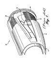
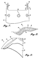
- the outer cowl panel 24 includes holes 28 ( FIGURE 7 ) through which the attachments for the actuator rods 18 extend ( FIGURE 1 ).
- Integral track fairings 30 extend rearwardly from the aft port and starboard side edges of the outer cowl panel 24.
- the track fairings 30 are shaped to minimize drag and to streamline airflow during normal (rearward thrust) operation of the jet engine.
- the track fairings 30 include a stepped transition area 32 that raises to an outer fairing surface 34.
- the outer fairing surface 34 is substantially parallel to the rear surface of the outer cowl panel 24.
- the stepped transition area 32 extends upward at an angle of approximately 115 degrees to the rear surface of the outer cowl panel 24.
- the radius for the curvature between the stepped transition area 32 and the rear surface of the outer cowl panel 24 is approximately 1.27 cm (0.5 inch).
- the outer fairing surface 34 of the track fairings 30 extends at an angle of approximately 88 degrees to the stepped transition area 32.
- the radius for the curvature between the outer fairing surface 34 and the stepped transition area 32 is approximately 1.9 cm (0.75 inch).
- Each track fairing 30 includes a structural honeycomb core 40 ( FIGURE 8 ) between an outer face sheet 42 and an inner face sheet 44. Formation of the honeycomb core 40 is shown in FIGURES 10-12 and 14-17 .
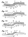
- FIGURES 10-12 illustrate the initial or "heat-forming" stages for formation of the honeycomb core 40 in which a honeycomb core sheet 50 is shaped against the male contour 54 of a shaping tool 52. Then the honeycomb core sheet 50 is flipped over and is shaped against a first concave lay-up mandrel 62 in a curing process shown in FIGURES 14-15 . The honeycomb core 40 is then machined from the honeycomb core sheet 50 in the process shown in FIGURES 16-17 .
- the shaping tool 52 has a male contour 54 that substantially matches the intended final contour of the side of the honeycomb core 40 that extends against the inner face sheet 44.
- the honeycomb core sheet 50 is preferably a fiberglass over-expanded core with phenolic resin.
- the present process can be used to form any core material that is difficult to shape into a complex geometry and which has a tendency not to maintain its shape after forming.
- a heat gun is used to form the honeycomb core sheet 50 against the male contour 54 of the shaping tool 52. Heat is applied to the areas where the honeycomb core sheet 50 is being bent as the honeycomb core sheet is slowly worked by hand in a forward-to-aft direction against the contour of the shaping tool 52. The forming process takes several minutes because the honeycomb core sheet 50 must be heated until the core material becomes plastic, so that the honeycomb core sheet can be formed around and against the contour of the shaping tool.
- the honeycomb core sheet 50 extends substantially against the outer contour 54 of the shaping tool 52.
- the shape for the honeycomb core 40 for the track fairings 30 is formed on the side of the honeycomb core sheet 50 opposite the shaping tool 52.
- the final shape for the honeycomb core 40 for the track fairings 30 is outlined by the dotted line 56 in FIGURE 12 .
- honeycomb core sheet 50 There is inherent spring-back in the honeycomb core sheet 50 caused by residual thermal stresses formed by shaping the honeycomb core sheet 50 against the mandrel during the heat-forming process. This spring-back causes the outer edges of the honeycomb core sheet 50 to separate from the outer contour 54 of the shaping tool 52 (shown generally by the arrows 58 in FIGURE 12 ). This inherent spring-back is useful in formation of the honeycomb core 40 for the track fairings 30, as will be described in detail below.
- a carrier ply 60 ( FIGURE 13 ) is used in the curing stage for the honeycomb core 40. As described in detail below, the carrier ply 60 structurally bonds pieces, including the honeycomb core 40, together to form a core assembly 72 ( FIGURE 18 ) that is used to form the outer cowl panel 24.
- the core assembly can be handled as a single unit during subsequent operations which greatly simplifies handling and positioning of the otherwise separate features or details.
- the carrier ply 60 is arranged on a first concave lay-up mandrel 62 ( FIGURE 19 ) that substantially matches the outer contour of the outer cowl panel 24.
- the carrier ply 60 is preferably a graphite fiber reinforced epoxy prepreg cut in the form of the outline for the outer edges of the outer cowl panel 24 with the fibers oriented +/- 45° to the longitudinal fore-to-aft axis of the nacelle.
- Additional carrier plys 64 are arranged on the upper contour 63 of the first concave lay-up mandrel 62 to provide strengthened localized access for fitting holes 28 in the outer cowl panel 24.
- the carrier ply 60 includes holes 66 at the locations where the honeycomb cores 40 for the track fairings 30 are to be placed and are also oriented +/- 45 degrees to the fore-to-aft axis of the nacelle 20.
- the honeycomb core sheet 50 is heat-formed to the shaping tool 52 in accordance with FIGURES 10-12 , the honeycomb core sheet 50 is removed from the shaping tool 52, flipped over, and arranged over the holes 66 in the carrier ply 60.
- the inherent spring-back built into the honeycomb core sheet 50 during the heat-forming process causes the outer edges of the honeycomb core sheet to press against the carrier ply 60, which in turn causes the central portion of the honeycomb core sheet to be spaced from the first concave lay-up mandrel 62 ( FIGURE 14 ).
- gaps 68 are formed between the central portions of the honeycomb core sheet 50 and the lay-up mandrel 62.
- fiberglass and aramid fiber honeycomb core 70 (shown in FIGURE 18 ) is extended over the carrier ply 60 and between the outer edges of the carrier ply and the circular carrier plies 64.
- the fiberglass and aramid core material 70 shown in FIGURE 18 is one or more pieces.
- the carrier ply 60, the circular carrier plies 64, the honeycomb core 40, and the fiberglass core material 70 form a core assembly 72.
- the core assembly 72 is vacuum bagged and placed in an autoclave.
- the core assembly 72 is then cured while suction is applied to the vacuum bag.
- the pressure applied by the autoclave (indicated by the arrows P in FIGURE 15 ) presses the honeycomb core sheet 50 against the first concave lay-up mandrel 62 and the carrier ply 60.
- the cured honeycomb core sheet 50 is a substantially stable structure.
- the cured honeycomb core sheet 50 maintains the shape of the outer contour of the first concave lay-up mandrel 62.
- the core assembly 72 After the core assembly 72 has been cured, the core assembly is machined, and the honeycomb core 40 for the track fairings 30 is cut and shaped along the dotted line 56.
- a cutting head 80 is shown in FIGURE 16 for removing the excess core material of the honeycomb core sheet 50.
- the cutting head 80 extends almost to, but not through, the carrier ply 60.
- the shape of the honeycomb core 40 for the track fairings 30 also contributes to relieving the inherent spring-back that is built into the honeycomb core sheet 50.
- Chamfers 74 are formed in the honeycomb core 40 for the track fairings 30 that help prevent the honeycomb core from releasing from the first concave lay-up mandrel 62.
- the inner surface 76 (farthest away from the first concave lay-up mandrel 62) of the honeycomb core sheet 50 at the outer edges of where the honeycomb core 40 is to be formed is machined away ( FIGURE 16 ). This inner surface 76 includes the majority of the residual thermal stresses formed within the honeycomb core sheet 50. The removal of the inner surface further assures that the honeycomb core 40 will maintain its shape after curing.
- the honeycomb core 40 for the track fairings 30 is a stable formation that is capable of maintaining its shape over an extremely tight contour. In this manner, the honeycomb core 40 for the track fairings 30 can be formed with the required radius for the stepped transition area 32 and the outer fairing surface 34.
- the outer cowl panel 24 is built up on a second concave lay-up mandrel 86 ( FIGURE 20 ).
- the second concave lay-up mandrel 86 includes an upper contour 87 that substantially matches the outer surface of the outer cowl panel 24.
- a first wet lay-up of prepreg sheets 88 is arranged on the outer contour of the second concave lay-up mandrel 86.
- the first wet lay-up of prepreg sheets 88 eventually forms the outer surface of the outer cowl panel 24, as well as the outer face sheet 42 for the integral track fairing 30.
- the first wet lay-up of prepreg sheets 88 is preferably carbon fibers impregnated with an epoxy resin.
- the first lay-up of prepreg sheets 88 includes a unique assembly at its leading end 89.
- the bottom two prepreg sheets 88A, 88B that are fitted against the upper contour 87 of the second concave lay-up mandrel 86 are preferably interwoven fiberglass impregnated with a resin.
- only the bottom prepreg sheet 88A is fiberglass impregnated with a resin.
- the fiberglass/resin prepreg sheets 88A and/or 88B provide extra resistance to wind erosion, as described in detail below.
- the adjacent prepreg sheets 88C, 88D, 88E and 88F are preferably woven carbon fibers impregnated with an epoxy resin.
- the fiberglass/resin prepreg sheets 88A, 88B can extend all the way to the integral track fairings 32, or only a few inches back from the leading edge 89 of the outer cowl panel 24. In a preferred embodiment of the invention, the fiberglass/resin prepreg sheets 88A, 88B extend rearwardly approximately 2.54 cm (1.0 inch) from the leading end 89 of the outer cowl panel.
- the fiberglass/resin prepreg sheets 88A, 88B extend forward beyond the adjacent prepreg sheets 88C, 88D, 88E and 88F.
- the adjacent prepreg sheets 88C, 88D, 88E and 88F are stepped so that the prepreg sheet 88C does not extend as far forward as the prepreg sheet 88D, the prepreg sheet 88D does not extend as far forward as the prepreg sheet 88E, and so forth.
- the prepreg sheets 88C, 88D, 88E and 88F are preferably stepped so that each of the prepreg sheets 88C, 88D, 88E and 88F extends the same amount beyond the adjacent prepreg sheet.
- the fiberglass/resin prepreg sheets 88A, 88B wrap upward to extend along the "steps" formed by the ends of the graphite prepreg sheets 88C, 88D, 88E and 88F.
- the core assembly 72 is arranged over the first lay-up of prepreg sheets.
- the core assembly 72 maintains its shape by the carrier ply 60 holding the fiberglass and aramid core material 70 and the specially shaped honeycomb cores 40 for the track fairings 30 in place.
- the carrier ply 60 also permits easy handling of the core assembly 72.
- a second wet lay-up of prepreg sheets 90 is arranged over the core assembly 72. The entire assembly is vacuum bagged on the lay-up mandrel, placed in a autoclave, and cured.
- the outer cowl panel 24 provides many benefits over prior art outer cowl panels.
- the present invention provides two steps for shaping a honeycomb core sheet 50 so as to form a stable honeycomb core 40 for a track fairing 30.
- the honeycomb core 40 is used to form a lightweight, core-reinforced composite outer cowl panel 24 in which the track fairings 30 are formed integrally with the outer cowl panel 24.
- Forming the track fairings 30 integrally with the outer cowl panel 24 is made possible by the two-step formation (heat-forming and then curing) of the honeycomb core 40 for the track fairings 30.
- thermal residual stresses and spring-back are formed on opposite sides of the core material, resulting in a stable final core.
- the two-step formation process for the honeycomb core for the track fairings minimizes the traditional spring-back characteristics of a core formed over a contoured shape.
- the spring-back characteristics are counteracted because the two-step process produces residual thermal stresses and spring-back characteristics on both sides of the honeycomb core 40 for the track fairings 30.
- the two-step process creates a stable core formation that is capable of maintaining its shape over a tightly contoured surface.
- the shape of the honeycomb core 40 for the track fairings 30 also contributes to relieving the inherent spring-back that is built into the honeycomb core sheet 50.
- the honeycomb core 40 for the track fairings 30 maintains the complex geometry of the first concave lay-up mandrel 62, and formation of the track fairings 30 with a honeycomb core 40 integral with an outer cowl panel 24 is possible.
- the outer cowl panel 24 does not require fasteners or brackets to attach separate fairings. Moreover, labor time and expense is reduced because the track fairings 30 do not require separate attachments and assembly. The reduction of parts results in a reduction in weight for the outer cowl panel 24. Applicants have found that the described method produces an outer cowl panel that is 33% lighter than prior art composite outer cowl panels.
- the arrangement at the leading edge of the first wet lay-up of prepreg sheets 88 provides another advantage over prior art outer cowl panels.
- the leading edge of the outer cowl panel 24 provides an aerodynamic chamfer without the need for a secondary, mechanically attached device.
- the aerodynamic chamfer slows erosion of prepreg sheets on the leading edge of the outer cowl panel 24.
Landscapes
- Engineering & Computer Science (AREA)
- Mechanical Engineering (AREA)
- Aviation & Aerospace Engineering (AREA)
- Chemical & Material Sciences (AREA)
- Composite Materials (AREA)
- Laminated Bodies (AREA)
- Body Structure For Vehicles (AREA)
Claims (4)
- Panneau extérieur de capot (24) pour une nacelle de moteur comprenant:un stratifié renforcé de fibres de carbone (88) ayant un bord d'attaque (89) défini par empilage d'une pluralité de plis pré-imprégnés de fibres de carbone (88C, 88D, 88E, 88F) pour former le stratifié ; etun pli de garnissage (88A, 88B) avec un renforcement en fibres de verre recouvrant le bord d'attaque (89) pour assurer une protection contre l'érosion, caractérisé en ce quela pluralité de plis (88C, 88D, 88E et 88F) sont étagés de sorte que le premier pli pré-imprégné (88C) adjacent au pli de garnissage ne s'étende pas autant en avant que le deuxième pli pré-imprégné (88D) suivant le premier pli dans le stratifié, que le troisième pli pré-imprégné (88D) suivant le second pli pré-imprégné dans le stratifié ne s'étende pas autant en avant que le deuxième pli pré-imprégné (88E), et ainsi de suite, de sorte que le pli de garnissage s'enroule vers le haut pour s'étendre le long des étages formés par les extrémités des plis de fibres de carbone.
- Panneau extérieur de capot (24) selon la revendication 1, dans lequel la pluralité de plis comprend :une première feuille de fibres/résine (88A, 88B), la première feuille de fibres/résine s'étendant vers l'extrémité d'attaque (89) du panneau extérieur de capot (24) afin de former une première extrémité ;une deuxième feuille de fibres/résine (88C), la deuxième feuille de fibres/résine s'étendant sur la première feuille de fibres/résine (88A, 88B) et s'étendant jusqu'à une seconde extrémité, la première extrémité étant plus proche de l'extrémité d'attaque (89) que la seconde extrémité ; etune troisième feuille de fibres/résine (88D) s'étendant sur et contre la deuxième feuille de fibres/résine (88C), la troisième feuille de fibres (88C) s'étendant au-delà de la seconde extrémité et vers le bas en direction de la première extrémité et fixant la première extrémité de sorte que la troisième feuille de fibres/résine (88D) forme le pli de garnissage.
- Panneau extérieur de capot selon la revendication 1 ou 2, dans lequel la pluralité de plis comprend en outre une quatrième feuille de fibres/résine (88E) s'étendant sur et contre la troisième feuille de fibres/résine (88D), l'extrémité d'attaque de la quatrième feuille de fibres/résine (88E) s'étendant vers le bas de manière à former le pli de garnissage avec la troisième feuille de fibres/résine (88C).
- Panneau extérieur de capot selon l'une quelconque des revendications 1 à 3, dans lequel les feuilles de fibres/résine (88A, 88B) s'étendent vers l'arrière à peu près à 2,5 cm (1,0 pouce) de l'extrémité d'attaque (89) du panneau extérieur de capot.
Applications Claiming Priority (3)
| Application Number | Priority Date | Filing Date | Title |
|---|---|---|---|
| US5428497P | 1997-07-30 | 1997-07-30 | |
| US09/013,993 US6129311A (en) | 1997-07-30 | 1998-01-27 | Engine nacelle outer cowl panel with integral track fairings |
| EP98202571A EP0894715B1 (fr) | 1997-07-30 | 1998-07-30 | Panneau extérieur d'un capot de nacelle d'un moteur avec des carénages d'un rail de guidage integrés et procédé pour sa fabrication |
Related Parent Applications (2)
| Application Number | Title | Priority Date | Filing Date |
|---|---|---|---|
| EP98202571A Division EP0894715B1 (fr) | 1997-07-30 | 1998-07-30 | Panneau extérieur d'un capot de nacelle d'un moteur avec des carénages d'un rail de guidage integrés et procédé pour sa fabrication |
| EP98202571.0 Division | 1998-07-30 |
Publications (3)
| Publication Number | Publication Date |
|---|---|
| EP1770011A2 EP1770011A2 (fr) | 2007-04-04 |
| EP1770011A3 EP1770011A3 (fr) | 2007-06-27 |
| EP1770011B1 true EP1770011B1 (fr) | 2011-05-25 |
Family
ID=26685519
Family Applications (2)
| Application Number | Title | Priority Date | Filing Date |
|---|---|---|---|
| EP98202571A Expired - Lifetime EP0894715B1 (fr) | 1997-07-30 | 1998-07-30 | Panneau extérieur d'un capot de nacelle d'un moteur avec des carénages d'un rail de guidage integrés et procédé pour sa fabrication |
| EP07001301A Expired - Lifetime EP1770011B1 (fr) | 1997-07-30 | 1998-07-30 | Panneau extérieur d'un capot de nacelle d'un moteur |
Family Applications Before (1)
| Application Number | Title | Priority Date | Filing Date |
|---|---|---|---|
| EP98202571A Expired - Lifetime EP0894715B1 (fr) | 1997-07-30 | 1998-07-30 | Panneau extérieur d'un capot de nacelle d'un moteur avec des carénages d'un rail de guidage integrés et procédé pour sa fabrication |
Country Status (3)
| Country | Link |
|---|---|
| US (1) | US6129311A (fr) |
| EP (2) | EP0894715B1 (fr) |
| DE (1) | DE69837640T2 (fr) |
Cited By (1)
| Publication number | Priority date | Publication date | Assignee | Title |
|---|---|---|---|---|
| US11047308B2 (en) | 2018-06-29 | 2021-06-29 | The Boeing Company | Acoustic panel for thrust reversers |
Families Citing this family (41)
| Publication number | Priority date | Publication date | Assignee | Title |
|---|---|---|---|---|
| US9586699B1 (en) | 1999-08-16 | 2017-03-07 | Smart Drilling And Completion, Inc. | Methods and apparatus for monitoring and fixing holes in composite aircraft |
| US9625361B1 (en) | 2001-08-19 | 2017-04-18 | Smart Drilling And Completion, Inc. | Methods and apparatus to prevent failures of fiber-reinforced composite materials under compressive stresses caused by fluids and gases invading microfractures in the materials |
| FR2862607B1 (fr) * | 2003-11-24 | 2007-03-23 | Airbus France | Cloison pour aeronef destinee a separer une partie cargo d'un cockpit ou d'un compartiment passager |
| DE102006044093B4 (de) * | 2006-09-20 | 2009-01-22 | Airbus Deutschland Gmbh | Scheibenersatz zum Ausfüllen eines Fensterrahmens |
| US7797944B2 (en) | 2006-10-20 | 2010-09-21 | United Technologies Corporation | Gas turbine engine having slim-line nacelle |
| US7870721B2 (en) * | 2006-11-10 | 2011-01-18 | United Technologies Corporation | Gas turbine engine providing simulated boundary layer thickness increase |
| US8002520B2 (en) * | 2007-01-17 | 2011-08-23 | United Technologies Corporation | Core reflex nozzle for turbofan engine |
| US8408491B2 (en) | 2007-04-24 | 2013-04-02 | United Technologies Corporation | Nacelle assembly having inlet airfoil for a gas turbine engine |
| US8205430B2 (en) * | 2007-05-16 | 2012-06-26 | United Technologies Corporation | Variable geometry nacelle assembly for a gas turbine engine |
| US8727267B2 (en) * | 2007-05-18 | 2014-05-20 | United Technologies Corporation | Variable contraction ratio nacelle assembly for a gas turbine engine |
| US8402739B2 (en) * | 2007-06-28 | 2013-03-26 | United Technologies Corporation | Variable shape inlet section for a nacelle assembly of a gas turbine engine |
| US9228534B2 (en) * | 2007-07-02 | 2016-01-05 | United Technologies Corporation | Variable contour nacelle assembly for a gas turbine engine |
| FR2921342B1 (fr) * | 2007-09-20 | 2010-03-12 | Airbus France | Carenage aerodynamique arriere inferieur pour dispositif d'accrochage d'un moteur d'aeronef |
| US9004399B2 (en) * | 2007-11-13 | 2015-04-14 | United Technologies Corporation | Nacelle flow assembly |
| US8186942B2 (en) * | 2007-12-14 | 2012-05-29 | United Technologies Corporation | Nacelle assembly with turbulators |
| US8192147B2 (en) * | 2007-12-14 | 2012-06-05 | United Technologies Corporation | Nacelle assembly having inlet bleed |
| US8529188B2 (en) * | 2007-12-17 | 2013-09-10 | United Technologies Corporation | Fan nacelle flow control |
| DE102008044759B4 (de) | 2008-08-28 | 2013-09-19 | Airbus Operations Gmbh | Stütze für ein im Selective Laser Melting-Verfahren herstellbares Flugzeugstrukturbauteil |
| US8220738B2 (en) * | 2008-11-26 | 2012-07-17 | Mra Systems, Inc. | Nacelle and method of assembling the same |
| US9188025B2 (en) * | 2008-11-26 | 2015-11-17 | Mra Systems, Inc. | Apparatus for facilitating access to a nacelle interior |
| US9188026B2 (en) * | 2008-11-26 | 2015-11-17 | Mra Systems, Inc. | Apparatus for facilitating access to a nacelle interior and method of assembling the same |
| US8172176B2 (en) * | 2009-02-04 | 2012-05-08 | Spirit Aerosystems, Inc. | Integral composite slider for aircrafts |
| DE102009058359A1 (de) * | 2009-12-15 | 2011-06-16 | Airbus Operations Gmbh | Krafteinleitungsbeschlag für Leichtbaukomponenten |
| FR2954278B1 (fr) * | 2009-12-18 | 2012-01-20 | Aircelle 7303 | Structure support pour inverseur de poussee notamment a grilles |
| US9057286B2 (en) | 2010-03-30 | 2015-06-16 | United Technologies Corporation | Non-circular aft nacelle cowling geometry |
| US8578609B2 (en) * | 2010-10-27 | 2013-11-12 | Airbus Operations S.L. | Manufacturing procedure of a part made out of a composite material introducing a geometric change in one of its faces |
| GB2485183A (en) * | 2010-11-04 | 2012-05-09 | Rolls Royce Plc | Generating residual stress in hollow body during cure to deflect composite body on relaxation |
| FR2970670A1 (fr) * | 2011-01-26 | 2012-07-27 | Aircelle Sa | Piece en materiau composite et procede de realisation d'une telle piece |
| DE102011018526A1 (de) * | 2011-04-26 | 2012-10-31 | Airbus Operations Gmbh | Krafteinleitungsbeschlag für Leichtbaukomponenten |
| FR2982588B1 (fr) * | 2011-11-10 | 2013-11-22 | Aircelle Sa | Panneau composite a ecope de prelevement integree |
| US9168716B2 (en) * | 2012-09-14 | 2015-10-27 | The Boeing Company | Metallic sandwich structure having small bend radius |
| US20150330254A1 (en) | 2014-05-15 | 2015-11-19 | United Technologies Corporation | Compact Nacelle With Contoured Fan Nozzle |
| US10196937B2 (en) * | 2015-12-30 | 2019-02-05 | General Electric Company | Method and system for improving structural characteristics of composite component corners |
| US10197007B2 (en) | 2016-01-14 | 2019-02-05 | General Electric Company | Method and system for controlling core cowl vent area |
| GB2570104B (en) * | 2017-12-18 | 2021-12-29 | Composite Integration Ltd | Improved system and method for resin transfer moulding |
| US10384723B2 (en) | 2017-12-19 | 2019-08-20 | Ford Global Technologies, Llc | Vehicle cross-car beam |
| CN109849370B (zh) * | 2019-03-20 | 2021-12-28 | 成都联科航空技术有限公司 | 一种火箭/导弹发动机级间连接结构的加工方法 |
| FR3095158B1 (fr) * | 2019-04-17 | 2021-04-30 | Hutchinson | Procédé de fabrication d’une grille pour un inverseur de poussée |
| GB2583751B (en) | 2019-05-09 | 2022-02-02 | Safran Nacelles Ltd | Acoustic panel |
| GB2588204B (en) | 2019-10-15 | 2022-09-14 | Safran Nacelles Ltd | Aircraft nacelle inlet |
| US11702982B2 (en) * | 2019-10-24 | 2023-07-18 | The Boeing Company | Blade fragment barrier for aircraft engine inlet cowl |
Family Cites Families (29)
| Publication number | Priority date | Publication date | Assignee | Title |
|---|---|---|---|---|
| US2654686A (en) * | 1950-05-11 | 1953-10-06 | Northrop Aircraft Inc | Stiffened honeycomb core |
| US3616112A (en) * | 1969-08-29 | 1971-10-26 | Balsa Dev Corp | Balsa wood core in a laminated structural sandwich |
| US3658974A (en) * | 1970-05-28 | 1972-04-25 | Nasa | Method of forming shapes from planar sheets of thermosetting materials |
| US4030290A (en) * | 1974-11-06 | 1977-06-21 | The Boeing Company | Jet engine thrust reverser |
| US4026105A (en) * | 1975-03-25 | 1977-05-31 | The Boeing Company | Jet engine thrust reverser |
| US4043522A (en) * | 1975-12-22 | 1977-08-23 | The Boeing Company | Common pod for housing a plurality of different turbofan jet propulsion engines |
| US4232513A (en) * | 1977-10-19 | 1980-11-11 | Rolls-Royce Limited | Pressure relief panel for aircraft powerplant |
| US4235303A (en) * | 1978-11-20 | 1980-11-25 | The Boeing Company | Combination bulk absorber-honeycomb acoustic panels |
| US4539244A (en) * | 1979-08-06 | 1985-09-03 | Rohr Industries, Inc. | Honeycomb noise attenuation structure |
| US4421201A (en) * | 1981-09-29 | 1983-12-20 | The Boeing Company | High efficiency broadband acoustic resonator and absorption panel |
| US4463552A (en) * | 1981-12-14 | 1984-08-07 | United Technologies Corporation | Combined surge bleed and dust removal system for a fan-jet engine |
| US4564160A (en) * | 1982-09-29 | 1986-01-14 | The Boeing Company | Thrust reverser blocker door assembly |
| US4495764A (en) * | 1983-05-26 | 1985-01-29 | The United States Of America As Represented By The Secretary Of The Air Force | Integrated insulation wall assembly |
| US4533098A (en) * | 1983-06-20 | 1985-08-06 | General Electric Company | Thrust reverser attachment |
| AT384189B (de) * | 1983-10-10 | 1987-10-12 | Fischer Gmbh | Bauplatte |
| US4852805A (en) * | 1983-12-30 | 1989-08-01 | The Boeing Company | Hybrid thrust reverser cascade basket and method |
| US4680216A (en) * | 1984-09-04 | 1987-07-14 | United Technologies Corporation | Method for stabilizing thick honeycomb core composite articles |
| US4600619A (en) * | 1984-12-31 | 1986-07-15 | The Boeing Company | Continuously wound filament structure for use in noise attenuation element |
| US4779240A (en) * | 1985-04-29 | 1988-10-18 | Xecutek Corporation | Ultrasonic sensor system |
| US4759513A (en) * | 1986-09-26 | 1988-07-26 | Quiet Nacelle Corporation | Noise reduction nacelle |
| US4826106A (en) * | 1987-02-18 | 1989-05-02 | Grumman Aerospace Corporation | Advanced composite aircraft cowl |
| US4825644A (en) * | 1987-11-12 | 1989-05-02 | United Technologies Corporation | Ventilation system for a nacelle |
| US5054281A (en) * | 1989-09-25 | 1991-10-08 | Rohr Industries, Inc. | Gas turbine engine compartment vent system |
| DE4130620C2 (de) * | 1991-09-14 | 1994-10-06 | Eurocopter Deutschland | Verfahren zum Biegeumformen eines ebenflächigen Gegenstandes mit Wabenstruktur |
| US5239822A (en) * | 1992-01-14 | 1993-08-31 | The Boeing Company | Composite structure for thrust reverser torque box |
| US5428498A (en) | 1992-09-28 | 1995-06-27 | Xerox Corporation | Office environment level electrostatic discharge protection |
| DE4343904C3 (de) | 1993-12-22 | 1999-11-04 | Mtu Muenchen Gmbh | Bauteil aus faserverstärktem Verbundwerkstoff mit einer Schutzschicht gegen Erosion |
| US5498462A (en) * | 1994-04-01 | 1996-03-12 | Hexcel Corporation | High thermal conductivity non-metallic honeycomb |
| GB9424495D0 (en) * | 1994-12-05 | 1995-01-25 | Short Brothers Plc | Aerodynamic low drag structure |
-
1998
- 1998-01-27 US US09/013,993 patent/US6129311A/en not_active Expired - Lifetime
- 1998-07-30 DE DE69837640T patent/DE69837640T2/de not_active Expired - Lifetime
- 1998-07-30 EP EP98202571A patent/EP0894715B1/fr not_active Expired - Lifetime
- 1998-07-30 EP EP07001301A patent/EP1770011B1/fr not_active Expired - Lifetime
Cited By (1)
| Publication number | Priority date | Publication date | Assignee | Title |
|---|---|---|---|---|
| US11047308B2 (en) | 2018-06-29 | 2021-06-29 | The Boeing Company | Acoustic panel for thrust reversers |
Also Published As
| Publication number | Publication date |
|---|---|
| EP1770011A2 (fr) | 2007-04-04 |
| EP1770011A3 (fr) | 2007-06-27 |
| DE69837640D1 (de) | 2007-06-06 |
| US6129311A (en) | 2000-10-10 |
| EP0894715A3 (fr) | 2000-04-19 |
| EP0894715A2 (fr) | 1999-02-03 |
| EP0894715B1 (fr) | 2007-04-25 |
| DE69837640T2 (de) | 2008-01-03 |
Similar Documents
| Publication | Publication Date | Title |
|---|---|---|
| EP1770011B1 (fr) | Panneau extérieur d'un capot de nacelle d'un moteur | |
| EP0894613B1 (fr) | Procédé pour la fabrication d'un panneau acoustique en matériau composite | |
| EP0895222B2 (fr) | Structure de renforcement pour des panneaux acoustiques d'une nacelle de réacteur | |
| US6173807B1 (en) | Engine nacelle acoustic panel with integral wedge fairings and an integral forward ring | |
| US4826106A (en) | Advanced composite aircraft cowl | |
| US10836472B2 (en) | One-piece composite bifurcated winglet | |
| JP5456473B2 (ja) | 航空機用の複合翼スラット | |
| US9211689B2 (en) | Composite material structures with integral composite fittings and methods of manufacture | |
| EP3626958B1 (fr) | Porte de blocage acoustique thermoplastique | |
| EP3594127B1 (fr) | Système de régulation de flux laminaire actif comportant un panneau composite | |
| US6319346B1 (en) | Method for manufacture of composite aircraft control surfaces | |
| US10738738B2 (en) | Nacelle with bifurcation extension and integral structural reinforcement | |
| EP3683140B1 (fr) | Bec de bord d'attaque d'avion, procédé de fabrication d'un tel bec | |
| WO2008111992A2 (fr) | Composants d'inverseur de poussée monolithiques | |
| AU679116B2 (en) | A duct cover for directing a fluid therethrough and a method for making the same | |
| CN110654527A (zh) | 用于推力反向器的吸声板 | |
| EP3812263B1 (fr) | Volet de bord de fuite ayant une structure intérieure en forme de grille | |
| EP3339619B1 (fr) | Ensemble, système et procédé de panneau de distribution de charge | |
| CA3001523A1 (fr) | Structure de fuselage sans lisse et procede de fabrication | |
| US10352273B2 (en) | Track beam with composite lug | |
| EP0895223B1 (fr) | Panneau acoustique pour une nacelle de moteur muni de carénage de cale et bague avant integrée | |
| US20240003329A1 (en) | Composite thermoplastic rotor blade with integral cuff | |
| EP4467313B1 (fr) | Fabrication d'un corps composite renforcé par des fibres avec de multiples couches stratifiées | |
| US20050178883A1 (en) | Helicopter tail rotor pylon |
Legal Events
| Date | Code | Title | Description |
|---|---|---|---|
| PUAI | Public reference made under article 153(3) epc to a published international application that has entered the european phase |
Free format text: ORIGINAL CODE: 0009012 |
|
| AC | Divisional application: reference to earlier application |
Ref document number: 0894715 Country of ref document: EP Kind code of ref document: P |
|
| AK | Designated contracting states |
Kind code of ref document: A2 Designated state(s): DE FR GB |
|
| PUAL | Search report despatched |
Free format text: ORIGINAL CODE: 0009013 |
|
| AK | Designated contracting states |
Kind code of ref document: A3 Designated state(s): DE FR GB |
|
| 17P | Request for examination filed |
Effective date: 20071227 |
|
| 17Q | First examination report despatched |
Effective date: 20080204 |
|
| AKX | Designation fees paid |
Designated state(s): DE FR GB |
|
| RTI1 | Title (correction) |
Free format text: ENGINE NACELLE OUTER COWL PANEL |
|
| GRAP | Despatch of communication of intention to grant a patent |
Free format text: ORIGINAL CODE: EPIDOSNIGR1 |
|
| GRAS | Grant fee paid |
Free format text: ORIGINAL CODE: EPIDOSNIGR3 |
|
| GRAA | (expected) grant |
Free format text: ORIGINAL CODE: 0009210 |
|
| AC | Divisional application: reference to earlier application |
Ref document number: 0894715 Country of ref document: EP Kind code of ref document: P |
|
| AK | Designated contracting states |
Kind code of ref document: B1 Designated state(s): DE FR GB |
|
| REG | Reference to a national code |
Ref country code: GB Ref legal event code: FG4D |
|
| REG | Reference to a national code |
Ref country code: DE Ref legal event code: R096 Ref document number: 69842291 Country of ref document: DE Effective date: 20110707 |
|
| PGFP | Annual fee paid to national office [announced via postgrant information from national office to epo] |
Ref country code: FR Payment date: 20110727 Year of fee payment: 14 |
|
| PGFP | Annual fee paid to national office [announced via postgrant information from national office to epo] |
Ref country code: GB Payment date: 20110727 Year of fee payment: 14 Ref country code: DE Payment date: 20110729 Year of fee payment: 14 |
|
| PLBE | No opposition filed within time limit |
Free format text: ORIGINAL CODE: 0009261 |
|
| STAA | Information on the status of an ep patent application or granted ep patent |
Free format text: STATUS: NO OPPOSITION FILED WITHIN TIME LIMIT |
|
| 26N | No opposition filed |
Effective date: 20120228 |
|
| REG | Reference to a national code |
Ref country code: DE Ref legal event code: R097 Ref document number: 69842291 Country of ref document: DE Effective date: 20120228 |
|
| GBPC | Gb: european patent ceased through non-payment of renewal fee |
Effective date: 20120730 |
|
| REG | Reference to a national code |
Ref country code: FR Ref legal event code: ST Effective date: 20130329 |
|
| PG25 | Lapsed in a contracting state [announced via postgrant information from national office to epo] |
Ref country code: FR Free format text: LAPSE BECAUSE OF NON-PAYMENT OF DUE FEES Effective date: 20120731 Ref country code: DE Free format text: LAPSE BECAUSE OF NON-PAYMENT OF DUE FEES Effective date: 20130201 Ref country code: GB Free format text: LAPSE BECAUSE OF NON-PAYMENT OF DUE FEES Effective date: 20120730 |
|
| REG | Reference to a national code |
Ref country code: DE Ref legal event code: R119 Ref document number: 69842291 Country of ref document: DE Effective date: 20130201 |