EP1770469A2 - Procédeé et appareil pour déterminer les données thermiques caractéristiques d'un radiateur - Google Patents
Procédeé et appareil pour déterminer les données thermiques caractéristiques d'un radiateur Download PDFInfo
- Publication number
- EP1770469A2 EP1770469A2 EP06017411A EP06017411A EP1770469A2 EP 1770469 A2 EP1770469 A2 EP 1770469A2 EP 06017411 A EP06017411 A EP 06017411A EP 06017411 A EP06017411 A EP 06017411A EP 1770469 A2 EP1770469 A2 EP 1770469A2
- Authority
- EP
- European Patent Office
- Prior art keywords
- radiator
- temperature
- flow
- ges
- thermal characteristics
- Prior art date
- Legal status (The legal status is an assumption and is not a legal conclusion. Google has not performed a legal analysis and makes no representation as to the accuracy of the status listed.)
- Granted
Links
Images


Classifications
-
- G—PHYSICS
- G01—MEASURING; TESTING
- G01K—MEASURING TEMPERATURE; MEASURING QUANTITY OF HEAT; THERMALLY-SENSITIVE ELEMENTS NOT OTHERWISE PROVIDED FOR
- G01K17/00—Measuring quantity of heat
- G01K17/06—Measuring quantity of heat conveyed by flowing media, e.g. in heating systems e.g. the quantity of heat in a transporting medium, delivered to or consumed in an expenditure device
- G01K17/08—Measuring quantity of heat conveyed by flowing media, e.g. in heating systems e.g. the quantity of heat in a transporting medium, delivered to or consumed in an expenditure device based upon measurement of temperature difference or of a temperature
- G01K17/10—Measuring quantity of heat conveyed by flowing media, e.g. in heating systems e.g. the quantity of heat in a transporting medium, delivered to or consumed in an expenditure device based upon measurement of temperature difference or of a temperature between an inlet and an outlet point, combined with measurement of rate of flow of the medium if such, by integration during a certain time-interval
-
- F—MECHANICAL ENGINEERING; LIGHTING; HEATING; WEAPONS; BLASTING
- F24—HEATING; RANGES; VENTILATING
- F24D—DOMESTIC- OR SPACE-HEATING SYSTEMS, e.g. CENTRAL HEATING SYSTEMS; DOMESTIC HOT-WATER SUPPLY SYSTEMS; ELEMENTS OR COMPONENTS THEREFOR
- F24D19/00—Details
- F24D19/10—Arrangement or mounting of control or safety devices
- F24D19/1006—Arrangement or mounting of control or safety devices for water heating systems
- F24D19/1009—Arrangement or mounting of control or safety devices for water heating systems for central heating
- F24D19/1048—Counting of energy consumption
-
- G—PHYSICS
- G05—CONTROLLING; REGULATING
- G05D—SYSTEMS FOR CONTROLLING OR REGULATING NON-ELECTRIC VARIABLES
- G05D23/00—Control of temperature
- G05D23/19—Control of temperature characterised by the use of electric means
- G05D23/1917—Control of temperature characterised by the use of electric means using digital means
-
- G—PHYSICS
- G05—CONTROLLING; REGULATING
- G05D—SYSTEMS FOR CONTROLLING OR REGULATING NON-ELECTRIC VARIABLES
- G05D23/00—Control of temperature
- G05D23/19—Control of temperature characterised by the use of electric means
- G05D23/1927—Control of temperature characterised by the use of electric means using a plurality of sensors
- G05D23/193—Control of temperature characterised by the use of electric means using a plurality of sensors sensing the temperaure in different places in thermal relationship with one or more spaces
- G05D23/1931—Control of temperature characterised by the use of electric means using a plurality of sensors sensing the temperaure in different places in thermal relationship with one or more spaces to control the temperature of one space
Definitions
- the invention relates to a method for determining thermal characteristics of a radiator, in which the radiator temperature and the room temperature are measured and converted with a correction variable into the desired thermal characteristics, and a system suitable for carrying out this method.
- ⁇ t is the calculation interval for the »mengeninkrement
- q is the current heater power Q nom the radiator rated power at the design point
- ⁇ log the current logarithmic temperature
- ⁇ log N hen the logarithmic temperature in the design point, for example, at the design point (90,70,20) ⁇ log
- 60 59.44 K
- n is the radiator exponent.
- the current logarithmic over-temperature ⁇ log can be determined, for example, with an electronic heat cost allocator, with two temperature sensors typically the radiator side temperature ⁇ HKS , eg the radiator surface temperature at the heating surface, and the room side temperature ⁇ RLS , in particular the radiator environment temperature in the vicinity of the radiator , to capture.
- the radiator-specific correction factors K Ges , K CW , K CL are calculated from the corresponding radiator-specific C values, which must be determined for each radiator either by measurement or simulatively. In today's practice of heating cost distribution, fixed values determined once as C values or correction factors K Ges , K CW , K CL are used.
- the object of the invention is therefore to propose universally applicable correction variables that can be used to determine a variety of or all thermal characteristics of the radiator.
- the correction variable depends on the current operating point of the radiator, which can be determined by the radiator flow temperature, the radiator return temperature, the radiator environment temperature, the radiator mass flow and / or the radiator valve position.
- the correction factor K GES is preferably used as the correction variable for determining the logarithmic overtemperature, because the latter has a direct influence on a large number of the heat characteristics of a radiator of interest.
- the correction factors K CW or K CL are used in the determination of the current radiator ambient temperature, for example when calculating radiator supply states or radiator flow or radiator return temperatures are needed, if the other temperature is known.
- the correction quantity should depend on the current operating point of the radiator. This is based on the finding that the correction value is by no means, as assumed in the previous methods, a constant value for a radiator, but that the correction variable depends in some cases considerably on the respective operating point of the radiator.
- the operating point of the radiator can already be determined with sufficient accuracy by determining one of the following variables radiator flow temperature, radiator return temperature, radiator environment, radiator mass flow and / or radiator valve position, so that the correction factor can be designed in particular as a function of one of these variables.
- the thermal characteristics themselves or other correction quantities may also depend as intermediate data on these quantities.
- the heat consumption which by using a fixed, radiator specific correction factor only an inaccurate calculation of the current logarithmic overtemperature, the current radiator heat output, the amount of heat or shallmengeninkrements or the like allow and For this reason, additional corrective mechanisms will be required, allowing correct calculation of the actual operating point of the radiator when calculating a correction quantity, thus allowing accurate determination of the thermal characteristics of a radiator without individual corrections for each individual size.
- the correction variable itself as a variable dependent on the radiator-specific C value, can be a quantity of the heat characteristics of the radiator of interest.
- the thermal characteristics and / or the correction quantity may depend on the radiator overtemperature, which is formed by the difference between the radiator temperature and the room temperature or radiator ambient temperature, and the radiator flow temperature and / or the radiator return temperature. These temperatures can be easily determined with the help of three radiator sensors, so that the method is particularly easy to implement metrologically.
- the measured temperature values in particular the radiator temperature, the room temperature and / or the radiator over-temperature are used as uncorrected temperature measurements.
- the only correction to be made for the determination of the plurality of heat characteristics of the radiator is thus in the operating point dependence of the correction quantity of the radiator.
- the correction variable and possibly also heat characteristics can be calculated in the form of a polynomial, which is mathematically easy to handle and with which the dependence of the correction variable from the operating point of the radiator with good and especially within the required accuracy reproduce sufficient precision.
- the polynomial which is used in particular for determining the correction quantity, may be formed as a function of the radiator temperature, the room temperature, the radiator ambient temperature or, preferably, the radiator overtemperature.
- the polynomial coefficients depend on this preferably from the radiator flow or the radiator return temperature. However, it is also possible to form the polynomial coefficients as a function of the radiator mass flow and the radiator valve position in order to map the operating point dependence of the radiator with sufficient accuracy in the polynomial coefficients.
- a second order polynomial can suitably describe the dependence of the correction quantity on the operating point of the radiator.
- discrete interpolation points in the function of the polynomial coefficients depending on the radiator flow temperature, the radiator return temperature, the radiator mass flow and / or the radiator valve position can be used to determine the polynomial coefficients at the operating point of the radiator. It has been found that four support points are sufficient in the required in practice workspace of the radiator for high accuracy. If, for example, the currently measured radiator flow or radiator return temperature lies between the predetermined interpolation points in which the polynomial coefficients were determined, known interpolation methods, for example linear interpolation, can be used.
- a calculation of thermal characteristics with a universal correction can be achieved particularly easily if the thermal characteristics, the correction variable and / or a polynomial coefficient depend on the radiator C values which decisively determine the properties of the radiator at the operating point.
- the thermal characteristics or calculation target variables of the radiator can be used as a correction factor correction factor, the uncorrected or logarithmic radiator overheating of the radiator, a radiator performance, a heat quantity increment, a radiator return or -allonslauf-, a Radiator mass flow, a radiator environment temperature, a radiator characteristic, a valve characteristic and / or a valve authority are determined.
- the valve lift position is known, for example, from an electronic individual room temperature control as a further input variable, so that the radiator or valve characteristic curve and ultimately also the valve authority can be automatically calculated on the fly. Therefore, the present method can also be used for the automatic adaptation of controller parameters for electronic individual space controls, similar to that in the DE 101 08 852 C2 described concept.
- the invention also relates to a system for determining thermal characteristics of a radiator, which is particularly suitable and adapted to carry out the method described above.
- the system has a first temperature sensor for detecting a radiator temperature, a second temperature sensor for detecting a room temperature, in particular the radiator ambient temperature, at least one further sensor for detecting the radiator flow temperature, the radiator return temperature, the radiator mass flow and / or the radiator valve position and a computing unit for calculating thermal characteristics on.
- the first and the second temperature sensor are integrated in a conventional heat cost allocator, as it is already widely used.
- the further sensor may be a radiator temperature or building flow temperature sensor, a radiator temperature return sensor, a mass flow sensor and / or a valve position sensor. It is also possible that the sensors are used for a single room temperature control, which is typically attached to the flow of a radiator and has a flow temperature and an ambient temperature sensor. Instead of a calculated (corrected) radiator environment correction, the measured room air temperature of the ambient temperature sensor can then be used as an additional auxiliary or reference variable for the calculation of the thermal characteristics.
- the arithmetic unit can be integrated in a data collector, which usually has a data processor anyway.
- the inventively proposed system in heating systems can be retrofitted, which have already been equipped with electronic and communication-capable heating cost allocators.
- only one further sensor preferably a flow or return temperature sensor is necessary.
- the logic necessary for carrying out the method according to the invention can easily be integrated into a centralized or decentralized, intelligent data collector, which preferably has bidirectional communication possibilities.
- the method sequence can also be installed by a rechargeable software in the arithmetic unit.
- the already existing technology of available, cost-effective electronic and communication-capable heat cost allocators For example, also radio heat cost allocators are used, which are easily installable or nachinstallierbar in existing heating systems.
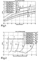
- the dependence of the correction factor on the operating point of the radiator characterized, for example, by the mass flow ratio or the measured excess temperature, is shown for various flow temperatures in FIGS. 1 and 2.
- the reference symbol 1 represents in each case the uncorrected, constant correction factor K GES .
- the actual dependency is shown by the solid lines with the reference numerals 2 to 6, which were measured in a test bench. Dotted lines represent an approximation of the correction factor K GES used according to the invention.
- a correction variable K GES is used, which depends on the current operating point of the radiator and takes into account the illustrated dependency.
- This correction quantity which is an intermediate quantity in the calculation of the heat characteristics of the radiator and correlated with the C-value of the radiator, can, for example, to calculate the current logarithmic overtemperature ⁇ log , the current radiator heat output Q ⁇ and the radiator heat quantity delivered or the display increment of the heat increment ⁇ Q of the heat cost allocator can be used.
- K GES which is a factor to the measured radiator and ambient temperatures
- a universal size is determined, which can be equally used to use all or a variety of thermal characteristics of the radiator, without individual corrections must be made ,
- the method is described in more detail for a first embodiment with reference to the signal flow diagram shown in FIG.
- a radiator temperature ⁇ HKS and a room temperature ⁇ RLS are measured, the difference of which gives the measured radiator overtemperature ⁇ .
- the measuring device on the radiator can be, for example, a heat cost allocator 1.
- the total flow temperature ⁇ GVL in the building is known, which is converted via a pipe model 2 in a radiator flow temperature ⁇ VL .
- the flow temperature loss is determined in the heating pipe system as a function of the length of the flow temperature supply to the radiator and possibly other factors such as position of the pipes, heat insulation jacket and the like.
- ⁇ HKS , ⁇ RLS or ⁇ and ⁇ VL are fed to a computing unit 3, which has a module 4 for determining a correction variable K GES , Kcw, K CL and a module 5 for determining thermal characteristics.
- the correction variable determined in the module 4 is one or more of the correction factors K GES , K CW , K CL .
- the correction factor K GES is multiplied by the difference between the measured, uncorrected temperature values ⁇ HKS and ⁇ RLS to the logarithmic radiator overtemperature ⁇ log , one of the heat characteristics of the radiator. Further thermal characteristics may be the actual radiator heat output Q ⁇ , the radiator heat increment ⁇ Q output, the costs associated with the amount of heat delivered.
- the correction variables K CW , K CL the return temperature (with known flow temperature or vice versa) can also be a supply state of the room or radiator for heat adaptation control and / or a radiator and valve characteristic.
- the operating point dependency is thus taken into account in that, in addition to the radiator side and room side temperatures, in particular the radiator surface temperature and the room air temperature measured in a heat cost allocator 1, either the radiator flow or the radiator return temperature is detected by measurement and included in the calculation of the intermediate and target variables (K GES , ⁇ log ua) is received. It is particularly advantageous to calculate the target or intermediate variable to be calculated as a function of the uncorrected, measured radiator overtemperature ⁇ and the additionally detected flow and return temperature ⁇ VL , ⁇ RL .
- the correction factor K GES , K CW , K CL or the corresponding target or intermediate size is calculated in the form of a polynomial, wherein the polynomial coefficient ⁇ m independent of the radiator overtemperature ⁇ as a function of the additionally detected flow or return temperature ⁇ VL , ⁇ RL are determined.
- ⁇ m independent of the radiator overtemperature ⁇ as a function of the additionally detected flow or return temperature ⁇ VL , ⁇ RL are determined.
- ⁇ VL below the lower base of the flow temperature, ⁇ VL above the upper interpolation point of the flow temperature and ⁇ EHKV ⁇ EHKV, HKS - ⁇ ENKV, RLS are the uncorrected EHKV overtemperature ⁇ .
- FIG. 3 The system for carrying out the method previously described with reference to FIG. 3 is shown in FIG.
- the illustrated system 6 has heating cost distributors 1 mounted on the radiators HK, which communicates via communication paths 7 with the arithmetic unit 3 containing the modules 4 and 5, which can be integrated, for example, in a data collector.
- the communication can be wired, via radio or via a powerline bus network, wherein any communication connections are basically suitable.
- a flow temperature sensor 8 which measures the total flow temperature of the building ⁇ GVL , is arranged on the building-central flow line of the radiator HK. These is converted in the arithmetic unit 3 by means of the pipe model 2 in a radiator flow temperature of the respective radiator HK.
- FIG. 5 shows a variant of the method described in FIG. 3, in which the flow temperature is not measured centrally at one point of the building, but in each case at the radiator flow. Therefore, the conversion of the entire flow temperature ⁇ GVL of the building in the pipe model 2 is omitted.
- the variant shown in Fig. 5 corresponds to the method described in Fig. 3, so that reference may be made to the above description.
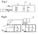
- the variants of the method or system according to the invention shown in FIGS. 7 and 8 are based on measuring the return temperature for determining the operating point of the radiator instead of the flow temperature, so that instead of the radiator flow temperature sensors 9 radiator return temperature sensors 10 are provided.
- the third embodiment of the invention works as previously described.
- FIGS. 9 and 10 describe further variants of the system 6 according to FIG. 4 for carrying out the method according to the invention, which are fundamentally similar, so that only the differences are discussed below.
- an air temperature sensor 11 is provided in the vicinity of each radiator HK for measuring the radiator ambient temperature, which instead of the calculated radiator ambient temperature as additional Auxiliary or reference size for the calculation of certain heat characteristics of the radiator, in particular a radiator supply state, can be used.
- the system 6 shown in FIG. 10 shows a combination, interesting in practice, of a heat cost allocator 1 and an electronic individual room temperature control 12, which has an actuator for the radiator valve and a flow temperature sensor 9. Furthermore, an additional room air temperature sensor can be integrated in the individual room temperature control 12.
- the attached to the radiator valve so typically radiator flow controller of electronic individual room temperature control 12 with a flow temperature and / or a room air temperature sensor can transmit the temperature values to the central or decentralized evaluation 3 and / or directly or indirectly to the associated heat cost allocators.
- the inventive method can be averted in an existing system without substantial subsequent installations and can be directly combined with solutions for communication-capable individual room temperature controls.
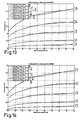
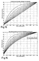
- FIGS. 11 to 16 show the results of the method according to the invention for determining the logarithmic overtemperature, the radiator output, the air temperature measured at the electric radiator distributor, and the actual air temperature, plotted against the mass flow ratio, in which the solid lines actually refer to one Test bench measured values, the dotted lines, the values derived from the uncorrected data and the dashed lines represent the results of the application of the present method, respectively for different flow temperatures.
- Figures 15 and 16 show the characteristics of linear control valves and relative heater power as a function of relative valve lift for various valve authorities.
- the radiator characteristics can also be determined from the calculated radiator mass flow and the radiator output. If, in addition, valve lift positions are still known, for example from an electronic individual room control, the radiator or valve characteristic curve and finally the valve authority can also be automatically calculated on the fly. These results can be used for the automatic adaptation of control parameters for electronic individual room control.
Landscapes
- Engineering & Computer Science (AREA)
- Physics & Mathematics (AREA)
- Chemical & Material Sciences (AREA)
- Combustion & Propulsion (AREA)
- Thermal Sciences (AREA)
- Mechanical Engineering (AREA)
- General Engineering & Computer Science (AREA)
- General Physics & Mathematics (AREA)
- Automation & Control Theory (AREA)
- Remote Sensing (AREA)
- Air Conditioning Control Device (AREA)
- Investigating Or Analyzing Materials Using Thermal Means (AREA)
Applications Claiming Priority (1)
| Application Number | Priority Date | Filing Date | Title |
|---|---|---|---|
| DE102005045198A DE102005045198C5 (de) | 2005-09-21 | 2005-09-21 | Verfahren und Vorrichtung zur Bestimmung von Wärmekenndaten eines Heizkörpers |
Publications (3)
| Publication Number | Publication Date |
|---|---|
| EP1770469A2 true EP1770469A2 (fr) | 2007-04-04 |
| EP1770469A3 EP1770469A3 (fr) | 2010-08-25 |
| EP1770469B1 EP1770469B1 (fr) | 2013-07-17 |
Family
ID=37103179
Family Applications (1)
| Application Number | Title | Priority Date | Filing Date |
|---|---|---|---|
| EP06017411.7A Active EP1770469B1 (fr) | 2005-09-21 | 2006-08-22 | Procédeé et appareil pour déterminer les données thermiques caractéristiques d'un radiateur |
Country Status (2)
| Country | Link |
|---|---|
| EP (1) | EP1770469B1 (fr) |
| DE (1) | DE102005045198C5 (fr) |
Cited By (15)
| Publication number | Priority date | Publication date | Assignee | Title |
|---|---|---|---|---|
| CN101290252B (zh) * | 2007-04-16 | 2010-09-08 | 北京众力德邦智能机电科技有限公司 | 一种用户采暖用热量的计量系统 |
| ITTO20100951A1 (it) * | 2010-11-30 | 2012-05-31 | Torino Politecnico | Gruppo contabilizzatore per impianti termici di riscaldamento / raffrescamento |
| CH705804A1 (de) * | 2011-11-28 | 2013-05-31 | Belimo Holding Ag | Verfahren zur Regelung der Raumtemperatur in einem Raum oder einer Gruppe von mehreren Räumen sowie eine Vorrichtung zur Durchführung des Verfahrens. |
| CN103162347A (zh) * | 2013-04-03 | 2013-06-19 | 黑龙江龙电电气有限公司 | 智能供暖计量系统及控制方法 |
| EP2157417A3 (fr) * | 2008-08-20 | 2014-03-05 | Metrona Wärmemesser Union Gmbh | Procédé de détermination de la répartition de la quantité de chaleur dans un système de chauffage pour radiateur |
| EP2327971A3 (fr) * | 2009-11-25 | 2014-04-30 | Metrona Wärmemesser Union Gmbh | Procédé d'analyse de la répartition des quantités de chaleur dans un système de chauffage et dispositif d'exécution du procédé |
| WO2018095609A3 (fr) * | 2016-11-22 | 2018-07-05 | Belimo Holding Ag | Système hydronique et procédé de fonctionnement d'un tel système hydronique |
| EP3376122A1 (fr) | 2017-03-17 | 2018-09-19 | Techem Energy Services GmbH | Procédé et dispositif de détermination d'émission de chaleur d'un radiateur |
| WO2019190341A1 (fr) * | 2018-03-28 | 2019-10-03 | Техем Энерджи Сервисиз Гмбх | Procédé de détermination de l'émission thermique d'un appareil de chauffage et distributeur de chaleur consommée |
| DE102018133080B3 (de) * | 2018-12-20 | 2020-02-20 | Qundis Gmbh | Verfahren zur Ermittlung eines Erwartungswertes einer Nennleistung eines unbekannten Heizkörpers und eines Erwartungswertes mindestens eines thermischen Kopplungsparameters eines elektronischen Heizkostenverteilers auf dem unbekannten Heizkörper und Parametrierverfahren zur Parametrierung eines elektronischen Heizkostenverteilers |
| DE102019106074A1 (de) * | 2019-03-11 | 2020-09-17 | Qundis Gmbh | Ermittlungsverfahren, mindestens zur Ermittlung mindestens eines c-Wertes für einen elektronischen Heizkostenverteiler, Parametrierverfahren zur Parametrierung des elektronischen Heizkostenverteilers und Vorrichtung zur Durchführung mindestens des Ermittlungsverfahrens |
| EP3492822B1 (fr) * | 2017-11-30 | 2020-09-30 | Minibems Limited | Procédé et dispositif de commande pour un système de chauffage ou de refroidissement |
| CN113432898A (zh) * | 2021-05-13 | 2021-09-24 | 天津电气科学研究院有限公司 | 散热器多点压接式测温铜块、性能测试装置及测试方法 |
| WO2024003043A1 (fr) * | 2022-06-27 | 2024-01-04 | Purmo Group Plc | Mesure de l'énergie de radiateurs |
| AT526287A1 (de) * | 2022-06-27 | 2024-01-15 | Purmo Group Plc | Energiemessung von Heizkörpern |
Families Citing this family (4)
| Publication number | Priority date | Publication date | Assignee | Title |
|---|---|---|---|---|
| DE102008054043A1 (de) | 2008-10-30 | 2010-05-12 | Techem Energy Services Gmbh | Verfahren und Vorrichtung zur wärmebedarfsgeführten Adaption der Vorlauftemperatur einer Heizungsanlage |
| CN106895478B (zh) * | 2017-02-10 | 2019-10-29 | 青岛高校信息产业股份有限公司 | 一种供热管网调节方法和系统 |
| DE102021203000B4 (de) | 2021-03-26 | 2023-01-19 | Qundis Gmbh | Verfahren zum Betrieb einer Heizkostenverteilervorrichtung und Heizkostenverteilervorrichtung |
| DE102021203001B4 (de) | 2021-03-26 | 2023-01-19 | Qundis Gmbh | Verfahren zum Betrieb einer Heizkostenverteilervorrichtung und Heizkostenverteilervorrichtung |
Family Cites Families (9)
| Publication number | Priority date | Publication date | Assignee | Title |
|---|---|---|---|---|
| DK134085B (da) * | 1974-02-22 | 1976-09-06 | Kamstrup Metro As | Varmemængdemåler. |
| US4455095A (en) * | 1980-05-08 | 1984-06-19 | Werner Bleiker | System for measuring the heat energy emission of room heating elements |
| DE3234850A1 (de) * | 1982-09-21 | 1984-03-22 | Ziesel, Gertrud, 7967 Bad Waldsee | Verfahren zur ermittlung der von einem installierten heizkoerper mit durchfliessendem medium abgegebenen waermemenge |
| DE59107770D1 (de) * | 1991-07-03 | 1996-06-05 | Bfw Werner Voelk Gmbh | Verfahren zur Ermittlung der Heizleistung der Heizkörper einer Einrohrheizung |
| DE9317309U1 (de) * | 1993-11-11 | 1994-01-27 | Offenhäußer, Thomas, 70825 Korntal-Münchingen | Mobile C-Wert-Erfassungsanlage |
| DE10108852C1 (de) * | 2001-02-23 | 2002-08-29 | Techem Service Ag | Raumtemperaturregelung |
| DE10108847C1 (de) * | 2001-02-23 | 2002-08-08 | Techem Service Ag | Verfahren und Vorrichtung zur Regelung der Raumlufttemperatur |
| ATE363648T1 (de) * | 2002-06-17 | 2007-06-15 | Olsberg Hermann Everken Gmbh | Verfahren zur ermittlung eines bewertungsfaktors eines heizgerätes, heizkostenverteiler für die durchführung des verfahrens sowie heizgerät mit einem derartigen heizkostenverteiler |
| DE10306465A1 (de) * | 2003-02-14 | 2004-09-02 | Siemens Building Technologies Ag | Verfahren zur Bestimmung des Zählfortschrittes in einem elektronischen Heizkostenverteiler, so dass die Möglichkeit des gemischten Einbaus von Heizkostenverteilern unterschiedlicher Bauart in einer Abrechnungseinheit (Mischverbau) besteht |
-
2005
- 2005-09-21 DE DE102005045198A patent/DE102005045198C5/de not_active Expired - Fee Related
-
2006
- 2006-08-22 EP EP06017411.7A patent/EP1770469B1/fr active Active
Cited By (25)
| Publication number | Priority date | Publication date | Assignee | Title |
|---|---|---|---|---|
| CN101290252B (zh) * | 2007-04-16 | 2010-09-08 | 北京众力德邦智能机电科技有限公司 | 一种用户采暖用热量的计量系统 |
| EP2157417A3 (fr) * | 2008-08-20 | 2014-03-05 | Metrona Wärmemesser Union Gmbh | Procédé de détermination de la répartition de la quantité de chaleur dans un système de chauffage pour radiateur |
| EP2327971A3 (fr) * | 2009-11-25 | 2014-04-30 | Metrona Wärmemesser Union Gmbh | Procédé d'analyse de la répartition des quantités de chaleur dans un système de chauffage et dispositif d'exécution du procédé |
| ITTO20100951A1 (it) * | 2010-11-30 | 2012-05-31 | Torino Politecnico | Gruppo contabilizzatore per impianti termici di riscaldamento / raffrescamento |
| CH705804A1 (de) * | 2011-11-28 | 2013-05-31 | Belimo Holding Ag | Verfahren zur Regelung der Raumtemperatur in einem Raum oder einer Gruppe von mehreren Räumen sowie eine Vorrichtung zur Durchführung des Verfahrens. |
| WO2013078570A1 (fr) * | 2011-11-28 | 2013-06-06 | Belimo Holding Ag | Procédé pour la régulation de la température ambiante dans un espace ou un groupe de plusieurs espaces, ainsi que dispositif pour la mise en œuvre du procédé |
| CN104105925A (zh) * | 2011-11-28 | 2014-10-15 | 贝利莫控股公司 | 用于调节在一个空间或一组多个空间中的空间温度的方法以及用于执行该方法的装置 |
| US9639099B2 (en) | 2011-11-28 | 2017-05-02 | Belimo Holding Ag | Method for regulating the room temperature in a room or in a group comprising multiple rooms, and apparatus for carrying out the method |
| CN104105925B (zh) * | 2011-11-28 | 2018-05-25 | 贝利莫控股公司 | 用于调节在一个空间或一组多个空间中的空间温度的方法以及用于执行该方法的装置 |
| CN103162347A (zh) * | 2013-04-03 | 2013-06-19 | 黑龙江龙电电气有限公司 | 智能供暖计量系统及控制方法 |
| CN103162347B (zh) * | 2013-04-03 | 2015-08-19 | 黑龙江龙电电气有限公司 | 智能供暖计量系统及控制方法 |
| US10890351B2 (en) | 2016-11-22 | 2021-01-12 | Belimo Holding Ag | Hydronic system and method for operating such hydronic system |
| WO2018095609A3 (fr) * | 2016-11-22 | 2018-07-05 | Belimo Holding Ag | Système hydronique et procédé de fonctionnement d'un tel système hydronique |
| EA035722B1 (ru) * | 2017-03-17 | 2020-07-30 | Техем Энерджи Сервисиз Гмбх | Способ и устройство для определения теплоотдачи отопительного прибора |
| EP3376122A1 (fr) | 2017-03-17 | 2018-09-19 | Techem Energy Services GmbH | Procédé et dispositif de détermination d'émission de chaleur d'un radiateur |
| EP3492822B1 (fr) * | 2017-11-30 | 2020-09-30 | Minibems Limited | Procédé et dispositif de commande pour un système de chauffage ou de refroidissement |
| WO2019190341A1 (fr) * | 2018-03-28 | 2019-10-03 | Техем Энерджи Сервисиз Гмбх | Procédé de détermination de l'émission thermique d'un appareil de chauffage et distributeur de chaleur consommée |
| DE102018133080B3 (de) * | 2018-12-20 | 2020-02-20 | Qundis Gmbh | Verfahren zur Ermittlung eines Erwartungswertes einer Nennleistung eines unbekannten Heizkörpers und eines Erwartungswertes mindestens eines thermischen Kopplungsparameters eines elektronischen Heizkostenverteilers auf dem unbekannten Heizkörper und Parametrierverfahren zur Parametrierung eines elektronischen Heizkostenverteilers |
| EP3671153B1 (fr) | 2018-12-20 | 2023-05-10 | QUNDIS GmbH | Procédé de détermination d'une valeur escomptée d'une puissance nominale d'un radiateur inconnu et d'une valeur escomptée d'au moins un paramètre d'accouplement thermique d'un répartiteur de coûts de chauffage électronique sur le radiateur inconnu et procédé de paramétrage d'un répartiteur de coûts de chauffage électronique |
| DE102019106074A1 (de) * | 2019-03-11 | 2020-09-17 | Qundis Gmbh | Ermittlungsverfahren, mindestens zur Ermittlung mindestens eines c-Wertes für einen elektronischen Heizkostenverteiler, Parametrierverfahren zur Parametrierung des elektronischen Heizkostenverteilers und Vorrichtung zur Durchführung mindestens des Ermittlungsverfahrens |
| DE102019106074B4 (de) | 2019-03-11 | 2022-06-15 | Qundis Gmbh | Ermittlungsverfahren, mindestens zur Ermittlung mindestens eines c-Wertes für einen elektronischen Heizkostenverteiler, Parametrierverfahren zur Parametrierung des elektronischen Heizkostenverteilers und Vorrichtung zur Durchführung mindestens des Ermittlungsverfahrens |
| EP3708984B1 (fr) * | 2019-03-11 | 2023-11-29 | QUNDIS GmbH | Procédé de détermination, permettant au moins de déterminer au moins une valeur c pour un répartiteur électronique de frais de chauffage, procédé de paramétrage du répartiteur électronique de frais de chauffage et dispositif permettant de mettre en uvre au moins le procédé de détermination |
| CN113432898A (zh) * | 2021-05-13 | 2021-09-24 | 天津电气科学研究院有限公司 | 散热器多点压接式测温铜块、性能测试装置及测试方法 |
| WO2024003043A1 (fr) * | 2022-06-27 | 2024-01-04 | Purmo Group Plc | Mesure de l'énergie de radiateurs |
| AT526287A1 (de) * | 2022-06-27 | 2024-01-15 | Purmo Group Plc | Energiemessung von Heizkörpern |
Also Published As
| Publication number | Publication date |
|---|---|
| DE102005045198C5 (de) | 2009-06-25 |
| EP1770469B1 (fr) | 2013-07-17 |
| DE102005045198B3 (de) | 2007-04-05 |
| EP1770469A3 (fr) | 2010-08-25 |
Similar Documents
| Publication | Publication Date | Title |
|---|---|---|
| EP1770469B1 (fr) | Procédeé et appareil pour déterminer les données thermiques caractéristiques d'un radiateur | |
| EP2874039B1 (fr) | Procédé de commande pour un système de transmission de chaleur et système de transmission de chaleur de ce type | |
| EP1936290B1 (fr) | Procédé et dispositif destinés à la détection de l'état hydraulique d'une installation de chauffage | |
| EP1933220B1 (fr) | Procédé de détermination de l'état d'alimentation d'un circuit de chauffage ou d'un bâtiment et régulateur d'état d'alimentation | |
| DE102017105740B4 (de) | Verfahren und Vorrichtung zur Erfassung der Wärmeabgabe eines Heizkörpers | |
| EP2738362B1 (fr) | Système de couplage chaleur-force | |
| EP3199876B1 (fr) | Procédé et dispositif destinés à influencer un réglage de chauffage | |
| DE3243198A1 (de) | Verfahren zur ermittlung des waermeverbrauchs von heizkoerpern und vorrichtung zur durchfuehrung des verfahrens zum zwecke der heizkostenverteilung | |
| EP3524951B2 (fr) | Répartiteur de frais de chauffage permettant de détecter la quantité de chaleur distribuée par un corps de chauffe | |
| EP2009536B1 (fr) | Procédé et dispositif destinés à l'ajustage de la réserve de puissance de chauffe | |
| DE3529257C2 (de) | Verfahren und Anordnung zur Ermittlung der Wärmeabgabe von Heizflächen einer Heizungsanlage | |
| EP1235131A2 (fr) | Régulation de la température d'une pièce | |
| EP1916585B1 (fr) | Procédé et dispositif destinés à la production des caractéristiques de température et à leur linéarisation | |
| EP2068138B1 (fr) | Procédé et dispositif de détermination de la délivrance de chaleur d'une surface de chauffage | |
| EP0632356B1 (fr) | Procédé pour l'optimisation automatique de la courbe de chauffage | |
| DE102016111280B4 (de) | Verfahren zur Ermittlung des Jahresnutzungsgrads einer wärmetechnischen Anlage | |
| DE19756104C5 (de) | Verfahren zur Regelung der Vorlauftemperatur einer Zentralheizungsanlage bzw. eines Heizkreises | |
| DE4127493C2 (de) | Thermo-Controller | |
| CH685021A5 (de) | Verfahren zur Anpassung einer fühlertypspezifischen Kennlinienfunktion eines Widerstands-Temperaturfühlers sowie Vorrichtung zur Durchführung des Verfahrens. | |
| DE102021203001B4 (de) | Verfahren zum Betrieb einer Heizkostenverteilervorrichtung und Heizkostenverteilervorrichtung | |
| DE3529256C2 (de) | Verfahren und Anordnung zum hydraulischen Abgleichen eines Heizkreislaufs | |
| DE3730529A1 (de) | Verfahren zur messung der durch das verhaeltnis von sollauslastung zur istauslastung definierten dimensionskennzahl eines heizaggregates einer heizungsanlage | |
| EP3708984B1 (fr) | Procédé de détermination, permettant au moins de déterminer au moins une valeur c pour un répartiteur électronique de frais de chauffage, procédé de paramétrage du répartiteur électronique de frais de chauffage et dispositif permettant de mettre en uvre au moins le procédé de détermination | |
| EP3483513A1 (fr) | Procédé de fonctionnement d'une installation de chauffage et installation de chauffage | |
| EP4063817A1 (fr) | Procédé de fonctionnement d'un dispositif de répartition des frais de chauffage et dispositif de répartition des frais de chauffage |
Legal Events
| Date | Code | Title | Description |
|---|---|---|---|
| PUAI | Public reference made under article 153(3) epc to a published international application that has entered the european phase |
Free format text: ORIGINAL CODE: 0009012 |
|
| AK | Designated contracting states |
Kind code of ref document: A2 Designated state(s): AT BE BG CH CY CZ DE DK EE ES FI FR GB GR HU IE IS IT LI LT LU LV MC NL PL PT RO SE SI SK TR |
|
| AX | Request for extension of the european patent |
Extension state: AL BA HR MK YU |
|
| PUAL | Search report despatched |
Free format text: ORIGINAL CODE: 0009013 |
|
| AK | Designated contracting states |
Kind code of ref document: A3 Designated state(s): AT BE BG CH CY CZ DE DK EE ES FI FR GB GR HU IE IS IT LI LT LU LV MC NL PL PT RO SE SI SK TR |
|
| AX | Request for extension of the european patent |
Extension state: AL BA HR MK RS |
|
| 17P | Request for examination filed |
Effective date: 20110215 |
|
| AKX | Designation fees paid |
Designated state(s): AT BE BG CH CY CZ DE DK EE ES FI FR GB GR HU IE IS IT LI LT LU LV MC NL PL PT RO SE SI SK TR |
|
| AXX | Extension fees paid |
Extension state: RS Payment date: 20110215 Extension state: HR Payment date: 20110215 Extension state: AL Payment date: 20110215 Extension state: BA Payment date: 20110215 Extension state: MK Payment date: 20110215 |
|
| REG | Reference to a national code |
Ref country code: DE Ref legal event code: R079 Ref document number: 502006013018 Country of ref document: DE Free format text: PREVIOUS MAIN CLASS: G05D0023190000 Ipc: F24D0019100000 |
|
| GRAP | Despatch of communication of intention to grant a patent |
Free format text: ORIGINAL CODE: EPIDOSNIGR1 |
|
| RIC1 | Information provided on ipc code assigned before grant |
Ipc: G05D 23/19 20060101ALI20130215BHEP Ipc: F24D 19/10 20060101AFI20130215BHEP Ipc: G01K 17/10 20060101ALI20130215BHEP |
|
| GRAS | Grant fee paid |
Free format text: ORIGINAL CODE: EPIDOSNIGR3 |
|
| GRAA | (expected) grant |
Free format text: ORIGINAL CODE: 0009210 |
|
| AK | Designated contracting states |
Kind code of ref document: B1 Designated state(s): AT BE BG CH CY CZ DE DK EE ES FI FR GB GR HU IE IS IT LI LT LU LV MC NL PL PT RO SE SI SK TR |
|
| AX | Request for extension of the european patent |
Extension state: AL BA HR MK RS |
|
| REG | Reference to a national code |
Ref country code: GB Ref legal event code: FG4D Free format text: NOT ENGLISH |
|
| REG | Reference to a national code |
Ref country code: CH Ref legal event code: EP |
|
| REG | Reference to a national code |
Ref country code: IE Ref legal event code: FG4D Free format text: LANGUAGE OF EP DOCUMENT: GERMAN |
|
| REG | Reference to a national code |
Ref country code: AT Ref legal event code: REF Ref document number: 622455 Country of ref document: AT Kind code of ref document: T Effective date: 20130815 |
|
| REG | Reference to a national code |
Ref country code: DE Ref legal event code: R096 Ref document number: 502006013018 Country of ref document: DE Effective date: 20130912 |
|
| REG | Reference to a national code |
Ref country code: CH Ref legal event code: NV Representative=s name: BOHEST AG, CH |
|
| REG | Reference to a national code |
Ref country code: NL Ref legal event code: VDEP Effective date: 20130717 |
|
| REG | Reference to a national code |
Ref country code: LT Ref legal event code: MG4D |
|
| PG25 | Lapsed in a contracting state [announced via postgrant information from national office to epo] |
Ref country code: PT Free format text: LAPSE BECAUSE OF FAILURE TO SUBMIT A TRANSLATION OF THE DESCRIPTION OR TO PAY THE FEE WITHIN THE PRESCRIBED TIME-LIMIT Effective date: 20131118 Ref country code: LT Free format text: LAPSE BECAUSE OF FAILURE TO SUBMIT A TRANSLATION OF THE DESCRIPTION OR TO PAY THE FEE WITHIN THE PRESCRIBED TIME-LIMIT Effective date: 20130717 Ref country code: IS Free format text: LAPSE BECAUSE OF FAILURE TO SUBMIT A TRANSLATION OF THE DESCRIPTION OR TO PAY THE FEE WITHIN THE PRESCRIBED TIME-LIMIT Effective date: 20131117 Ref country code: CY Free format text: LAPSE BECAUSE OF FAILURE TO SUBMIT A TRANSLATION OF THE DESCRIPTION OR TO PAY THE FEE WITHIN THE PRESCRIBED TIME-LIMIT Effective date: 20130717 Ref country code: SE Free format text: LAPSE BECAUSE OF FAILURE TO SUBMIT A TRANSLATION OF THE DESCRIPTION OR TO PAY THE FEE WITHIN THE PRESCRIBED TIME-LIMIT Effective date: 20130717 |
|
| BERE | Be: lapsed |
Owner name: TECHEM ENERGY SERVICES G.M.B.H. Effective date: 20130831 |
|
| PG25 | Lapsed in a contracting state [announced via postgrant information from national office to epo] |
Ref country code: NL Free format text: LAPSE BECAUSE OF FAILURE TO SUBMIT A TRANSLATION OF THE DESCRIPTION OR TO PAY THE FEE WITHIN THE PRESCRIBED TIME-LIMIT Effective date: 20130717 Ref country code: PL Free format text: LAPSE BECAUSE OF FAILURE TO SUBMIT A TRANSLATION OF THE DESCRIPTION OR TO PAY THE FEE WITHIN THE PRESCRIBED TIME-LIMIT Effective date: 20130717 Ref country code: LV Free format text: LAPSE BECAUSE OF FAILURE TO SUBMIT A TRANSLATION OF THE DESCRIPTION OR TO PAY THE FEE WITHIN THE PRESCRIBED TIME-LIMIT Effective date: 20130717 Ref country code: ES Free format text: LAPSE BECAUSE OF FAILURE TO SUBMIT A TRANSLATION OF THE DESCRIPTION OR TO PAY THE FEE WITHIN THE PRESCRIBED TIME-LIMIT Effective date: 20131028 Ref country code: FI Free format text: LAPSE BECAUSE OF FAILURE TO SUBMIT A TRANSLATION OF THE DESCRIPTION OR TO PAY THE FEE WITHIN THE PRESCRIBED TIME-LIMIT Effective date: 20130717 Ref country code: SI Free format text: LAPSE BECAUSE OF FAILURE TO SUBMIT A TRANSLATION OF THE DESCRIPTION OR TO PAY THE FEE WITHIN THE PRESCRIBED TIME-LIMIT Effective date: 20130717 Ref country code: GR Free format text: LAPSE BECAUSE OF FAILURE TO SUBMIT A TRANSLATION OF THE DESCRIPTION OR TO PAY THE FEE WITHIN THE PRESCRIBED TIME-LIMIT Effective date: 20131018 |
|
| PG25 | Lapsed in a contracting state [announced via postgrant information from national office to epo] |
Ref country code: SK Free format text: LAPSE BECAUSE OF FAILURE TO SUBMIT A TRANSLATION OF THE DESCRIPTION OR TO PAY THE FEE WITHIN THE PRESCRIBED TIME-LIMIT Effective date: 20130717 Ref country code: MC Free format text: LAPSE BECAUSE OF FAILURE TO SUBMIT A TRANSLATION OF THE DESCRIPTION OR TO PAY THE FEE WITHIN THE PRESCRIBED TIME-LIMIT Effective date: 20130717 Ref country code: DK Free format text: LAPSE BECAUSE OF FAILURE TO SUBMIT A TRANSLATION OF THE DESCRIPTION OR TO PAY THE FEE WITHIN THE PRESCRIBED TIME-LIMIT Effective date: 20130717 Ref country code: EE Free format text: LAPSE BECAUSE OF FAILURE TO SUBMIT A TRANSLATION OF THE DESCRIPTION OR TO PAY THE FEE WITHIN THE PRESCRIBED TIME-LIMIT Effective date: 20130717 Ref country code: RO Free format text: LAPSE BECAUSE OF FAILURE TO SUBMIT A TRANSLATION OF THE DESCRIPTION OR TO PAY THE FEE WITHIN THE PRESCRIBED TIME-LIMIT Effective date: 20130717 Ref country code: CZ Free format text: LAPSE BECAUSE OF FAILURE TO SUBMIT A TRANSLATION OF THE DESCRIPTION OR TO PAY THE FEE WITHIN THE PRESCRIBED TIME-LIMIT Effective date: 20130717 |
|
| REG | Reference to a national code |
Ref country code: IE Ref legal event code: MM4A |
|
| PLBE | No opposition filed within time limit |
Free format text: ORIGINAL CODE: 0009261 |
|
| REG | Reference to a national code |
Ref country code: FR Ref legal event code: ST Effective date: 20140430 |
|
| STAA | Information on the status of an ep patent application or granted ep patent |
Free format text: STATUS: NO OPPOSITION FILED WITHIN TIME LIMIT |
|
| PG25 | Lapsed in a contracting state [announced via postgrant information from national office to epo] |
Ref country code: IT Free format text: LAPSE BECAUSE OF FAILURE TO SUBMIT A TRANSLATION OF THE DESCRIPTION OR TO PAY THE FEE WITHIN THE PRESCRIBED TIME-LIMIT Effective date: 20130717 Ref country code: BE Free format text: LAPSE BECAUSE OF NON-PAYMENT OF DUE FEES Effective date: 20130831 |
|
| 26N | No opposition filed |
Effective date: 20140422 |
|
| GBPC | Gb: european patent ceased through non-payment of renewal fee |
Effective date: 20131017 |
|
| PG25 | Lapsed in a contracting state [announced via postgrant information from national office to epo] |
Ref country code: IE Free format text: LAPSE BECAUSE OF NON-PAYMENT OF DUE FEES Effective date: 20130822 Ref country code: GB Free format text: LAPSE BECAUSE OF NON-PAYMENT OF DUE FEES Effective date: 20131017 |
|
| REG | Reference to a national code |
Ref country code: DE Ref legal event code: R097 Ref document number: 502006013018 Country of ref document: DE Effective date: 20140422 Ref country code: CH Ref legal event code: PCAR Free format text: NEW ADDRESS: HOLBEINSTRASSE 36-38, 4051 BASEL (CH) |
|
| PG25 | Lapsed in a contracting state [announced via postgrant information from national office to epo] |
Ref country code: FR Free format text: LAPSE BECAUSE OF NON-PAYMENT OF DUE FEES Effective date: 20130917 |
|
| PG25 | Lapsed in a contracting state [announced via postgrant information from national office to epo] |
Ref country code: TR Free format text: LAPSE BECAUSE OF FAILURE TO SUBMIT A TRANSLATION OF THE DESCRIPTION OR TO PAY THE FEE WITHIN THE PRESCRIBED TIME-LIMIT Effective date: 20130717 |
|
| PG25 | Lapsed in a contracting state [announced via postgrant information from national office to epo] |
Ref country code: LU Free format text: LAPSE BECAUSE OF NON-PAYMENT OF DUE FEES Effective date: 20130822 Ref country code: BG Free format text: LAPSE BECAUSE OF FAILURE TO SUBMIT A TRANSLATION OF THE DESCRIPTION OR TO PAY THE FEE WITHIN THE PRESCRIBED TIME-LIMIT Effective date: 20130717 Ref country code: HU Free format text: LAPSE BECAUSE OF FAILURE TO SUBMIT A TRANSLATION OF THE DESCRIPTION OR TO PAY THE FEE WITHIN THE PRESCRIBED TIME-LIMIT; INVALID AB INITIO Effective date: 20060822 |
|
| PGFP | Annual fee paid to national office [announced via postgrant information from national office to epo] |
Ref country code: AT Payment date: 20180821 Year of fee payment: 13 Ref country code: CH Payment date: 20180827 Year of fee payment: 13 |
|
| REG | Reference to a national code |
Ref country code: AT Ref legal event code: MM01 Ref document number: 622455 Country of ref document: AT Kind code of ref document: T Effective date: 20190822 |
|
| PG25 | Lapsed in a contracting state [announced via postgrant information from national office to epo] |
Ref country code: AT Free format text: LAPSE BECAUSE OF NON-PAYMENT OF DUE FEES Effective date: 20190822 |
|
| PG25 | Lapsed in a contracting state [announced via postgrant information from national office to epo] |
Ref country code: CH Free format text: LAPSE BECAUSE OF NON-PAYMENT OF DUE FEES Effective date: 20190831 Ref country code: LI Free format text: LAPSE BECAUSE OF NON-PAYMENT OF DUE FEES Effective date: 20190831 |
|
| P01 | Opt-out of the competence of the unified patent court (upc) registered |
Effective date: 20230527 |
|
| PGFP | Annual fee paid to national office [announced via postgrant information from national office to epo] |
Ref country code: DE Payment date: 20240926 Year of fee payment: 19 |
|
| REG | Reference to a national code |
Ref country code: DE Ref legal event code: R119 Ref document number: 502006013018 Country of ref document: DE |