EP1770635A1 - Méthode itérative d'interpolation d'image - Google Patents
Méthode itérative d'interpolation d'image Download PDFInfo
- Publication number
- EP1770635A1 EP1770635A1 EP06020428A EP06020428A EP1770635A1 EP 1770635 A1 EP1770635 A1 EP 1770635A1 EP 06020428 A EP06020428 A EP 06020428A EP 06020428 A EP06020428 A EP 06020428A EP 1770635 A1 EP1770635 A1 EP 1770635A1
- Authority
- EP
- European Patent Office
- Prior art keywords
- image
- interpolated
- interpolation
- pixels
- image information
- Prior art date
- Legal status (The legal status is an assumption and is not a legal conclusion. Google has not performed a legal analysis and makes no representation as to the accuracy of the status listed.)
- Granted
Links
Images







Classifications
-
- G—PHYSICS
- G06—COMPUTING OR CALCULATING; COUNTING
- G06T—IMAGE DATA PROCESSING OR GENERATION, IN GENERAL
- G06T3/00—Geometric image transformations in the plane of the image
- G06T3/40—Scaling of whole images or parts thereof, e.g. expanding or contracting
- G06T3/4007—Scaling of whole images or parts thereof, e.g. expanding or contracting based on interpolation, e.g. bilinear interpolation
-
- H—ELECTRICITY
- H04—ELECTRIC COMMUNICATION TECHNIQUE
- H04N—PICTORIAL COMMUNICATION, e.g. TELEVISION
- H04N7/00—Television systems
- H04N7/01—Conversion of standards, e.g. involving analogue television standards or digital television standards processed at pixel level
- H04N7/0117—Conversion of standards, e.g. involving analogue television standards or digital television standards processed at pixel level involving conversion of the spatial resolution of the incoming video signal
- H04N7/012—Conversion between an interlaced and a progressive signal
-
- H—ELECTRICITY
- H04—ELECTRIC COMMUNICATION TECHNIQUE
- H04N—PICTORIAL COMMUNICATION, e.g. TELEVISION
- H04N7/00—Television systems
- H04N7/01—Conversion of standards, e.g. involving analogue television standards or digital television standards processed at pixel level
- H04N7/0135—Conversion of standards, e.g. involving analogue television standards or digital television standards processed at pixel level involving interpolation processes
- H04N7/014—Conversion of standards, e.g. involving analogue television standards or digital television standards processed at pixel level involving interpolation processes involving the use of motion vectors
Definitions
- the present invention relates to an iterative interpolation method for determining at least one interpolated image information value in an image which has a number of image-like image regions with original image regions to which an image information value has already been assigned and at least one image region to be interpolated.
- Interpolation methods for obtaining an image information value for an image area are needed in image processing for various applications.
- One application is the generation of frames from fields transmitted in television technology.
- an intermediate line is interpolated with a number of pixels to obtain a frame.
- An interpolation method for generating such intermediate lines is for example in DE 102 36 208 A1 (Hahn et al. ) or the DE 102 32 372 A1 (Hahn et al ).
- Another application for an interpolation method is to increase the image resolution.
- additional lines and columns are created by interpolation between existing rows and columns of an image in order to increase the image resolution.
- a method for this purpose is for example in the US 6,229,570 B1 (Bugwadia et al. ).
- Interpolation methods are also required in image transmission methods in which an image to be transmitted is divided into image blocks and transmitted in blocks. If a block is not transmitted due to a transmission error or incorrectly transmitted, its image content is to be interpolated on the receiver side.
- a method for this purpose is, for example, in Meisinger, Kaup: “Local error concealment of distorted received image data by frequency-selective extrapolation", Electronic Media: 10th Dortmunder TV Seminar, ITG-Fachbericht 179, pages 189-194 September 2003 , described.
- Another application for interpolation methods in image processing is to increase the resolution of a motion vector field.
- image processing it is well known to divide an image that is part of an image sequence with several successive images into individual image blocks and to assign a motion vector to each of these image blocks by means of a motion estimation method. These vectors together form a motion vector field.
- Such a motion vector associated with a block contains information about at which position in a previous and / or subsequent picture of the picture sequence the content of this block is found again. This information can be used for motion-correct generation of intermediate images between two images of a sequence of images.
- the motion estimation it is desirable to obtain blocks as small as possible, each of which has a motion vector associated therewith. However, this increases the effort in the motion estimation.
- the aim of the present invention is to provide an improved interpolation method for determining at least one interpolated image information value in an image, which has a number of image areas arranged in a matrix with original image areas to which an image information value has already been assigned, and with at least one image area to be interpolated.
- the method according to the invention is applied to an image which is subdivided into a number of image regions, of which some image regions are already assigned an image information value in each case.
- image areas to which an image information value has already been assigned, for which therefore no image information value has to be interpolated, are referred to below as "original image areas”.
- the image also comprises at least one image area to be interpolated, to which an image information value is to be interpolated.
- This image information value is hereinafter referred to as "interpolated image information value”.
- Each image area comprises at least one pixel, that is to say it may consist of a single pixel or else of several pixels arranged in the manner of a matrix.
- a multi-pixel image area will hereinafter be referred to as an "image block”.
- An image information value in the context of the present invention may be a luminance value, a chrominance value, or a motion vector value, the latter including two motion vector components.
- interpolation direction refers to a specific image direction in which the image regions are arranged adjacent to one another whose image information values are used to determine the interpolated image information value.
- the quality measure for an image direction determined from at least one group of image areas located adjacent in this image direction is determined to include information about how much the image information values of that group differ from each other. In this case, a direction is considered to be better, or the "goodness" of this direction is the higher, the less the image information values arranged adjacently in this direction deviate from one another.
- the quality measure can be generated so that it increases with increasing quality of an image direction or decreases with increasing quality of an image direction.
- the image direction is selected as the direction of interpolation, for which the comparison of the quality measures yields the highest quality.
- One way to determine a quality measure for an image direction among at least one group of image areas is to subject the image information values of these image areas to high-pass filtering to obtain a high-pass filter value.
- the amount of this high-pass filter value or a power of this high-pass filter value with an exponent which is a multiple of two forms the measure of quality.
- the quality measure whose value is the smaller the less the image information values of the image areas of the considered group differ from each other.
- a quality measure determined using only a group of image areas will hereinafter be referred to as "single quality measure".
- multiple quality measure Preferably, several individual quality measures are determined for determining the quality measure for an image direction, that is, a plurality of groups with image regions which are arranged adjacent in this image direction are examined.
- the "individual quality measures” are added here, for example, in order to obtain the quality measure for the image direction.
- the qualities of at least two image directions are compared, namely the quality of the image direction forming the start interpolation direction and the quality of at least one other image direction different from the start interpolation direction, and at the end of each iteration step an interpolated image information value provided.
- This interpolated image information value represents the final image information value assigned to the image area to be interpolated.
- the method steps c) and d) are preferably repeated until a predetermined end condition is reached.
- the end condition is reached when a predetermined number of iteration steps has been performed.
- the end condition is reached when the quality measure of the image direction, which is selected as the direction of interpolation, meets a predetermined quality criterion, that is, the quality value - depending on the type of determination of the quality value is above or below a predetermined threshold value.
- the image area assigned to the image area to be interpolated which is used for the interpolation, can change with each iteration step. If the image area to be interpolated is part of the at least one group of image areas that is examined for the determination of the quality measure of an image direction, the quality measure of this one image direction can likewise change from iteration step to iteration step, such that a comparison of the quality measures of two image directions depends on the number of iteration steps performed can lead to different results.
- a new image direction is preferably examined by determining the quality measure with each iteration step, wherein the best image direction so far, ie the image direction with the best quality measure, is used as a start interpolation direction during an interpolation step.
- the image directions examined during an interpolation step are selected such that an angle between the first start interpolation direction specified at the beginning of the method in step a) and the image direction examined during an interpolation step increases with each additional interpolation step.
- the generation of the interpolated image information value using image information values of the image areas adjacent to each other in the direction of interpolation may be performed by conventional filtering means, such as low-pass filtering of the image information values of those image areas.
- the groups of image areas which are used for determining the quality measure for an image direction may be selected such that they contain the image area to be interpolated.
- the image information value of the image area to be interpolated is the interpolated image information value from the respective preceding iteration step.
- a start interpolation value is generated in this case.
- image information values of those image areas are used which are arranged in the start-up interpolation direction adjacent to one another and adjacent to the image area to be interpolated. This start interpolation value can then be used in the determination of the quality measure for the start interpolation direction or the at least one further image direction.
- the at least one group of image regions, which is examined to determine the quality measure for an image direction may comprise at least one further image region to be interpolated.
- the method according to the invention is carried out in parallel for the image area to be interpolated and this at least one further image area to be interpolated such that an interpolation value is determined for the at least one further image area to be interpolated even before the quality measures for the start interpolation direction and the at least another picture direction be determined during the determination of the interpolated image information value for the one image area to be interpolated.
- the group of image areas which are adjacent to each other in the interpolation direction and whose image information values are used for the determination of the interpolated image information value are preferably selected to be original image areas.
- the method according to the invention can be used in many ways in image processing. Thus, it is possible to use this method in the inter-row interpolation already explained above.
- the image here comprises a number of original lines, each comprising a number of pixels, each associated with an image information value. Between two original lines, in each case at least one intermediate line is to be interpolated, which comprises a number of pixels to be interpolated.
- the individual pixels in each case form an image area for carrying out the method according to the invention, and the method is applied to each pixel of an interline to be interpolated.
- the method according to the invention can also be used for increasing the resolution in the motion estimation.
- An image is hereby divided into a number of first image blocks, to each of which a motion vector is assigned. Subsequently, the image is subdivided into a number of smaller second image blocks, preferably in such a way that a first group of second image blocks is created, which lie completely within a first image block, respectively, and a second group of second image blocks is created, which are represented by sections of two adjacent image blocks first image blocks are formed.
- the second image blocks of the first group form for carrying out the method according to the invention original image areas, where the motion vectors of the respective are assigned to the first image blocks, while the second image blocks for carrying out the method according to the invention form image areas to be interpolated.
- Motion vectors typically include two motion vector components.
- the method according to the invention is preferably carried out twice to resolve the motion estimation, namely separately for the first motion vector component and the second motion vector component.
- the inventive method is also suitable for the interpolation of image blocks that were not transmitted or incorrectly transmitted in the transmission of image data. If such an image block to be interpolated comprises a plurality of pixels arranged in the form of a matrix, the method according to the invention is preferably carried out several times in succession, the size of the image regions to be interpolated being reduced with each implementation of the method.
- the image block to be interpolated is initially assumed to be an image area to be interpolated, and by means of the method according to the invention a common image information value, ie a common brightness value or chrominance value, is assigned to this image area.
- the resolution of the correctly transmitted image blocks of the image is first coarsened for this purpose, ie in the environment of the image block to be interpolated, individual pixels are combined into image blocks having the same size as the image block to be interpolated, and each image block is assigned an image information value, for example by low-pass filtering Image information values of the individual pixels of the respective image block.
- the resulting image blocks form original image areas for carrying out the method according to the invention.
- the resolution of the image block to be interpolated is reduced by dividing the image block into a plurality of smaller image blocks corresponding to image areas to be interpolated for the method according to the invention.
- the resolution of the correctly transmitted picture blocks surrounded by the picture block to be interpolated is increased and the method according to the invention is carried out again for the "smaller" picture areas of the picture block to be interpolated in total.
- the method according to the invention is repeated until the same resolution is achieved for the image block to be interpolated as for its surroundings.
- Figure 1a schematically shows a section of such an image, the original image lines 1, 3, 5, 7, which are each divided into a number of pixels 11.
- These picture lines 1, 3, 5, 7 are, for example, picture lines of a field known from television broadcasting.
- a further image line 2, 4, 6, which is referred to below as an intermediate line and each comprising a number of pixels
- the pixels of the original image lines 1, 3, 5, 7 are shown in Figure 1a as squares with solid lines, while the pixels of the intermediate lines 2, 4, 6 are shown as squares with partially dashed lines.
- the original picture lines 1, 3, 5, 7 with the original picture elements and the intermediate lines 2, 4, 6 to be interpolated with the picture elements to be interpolated are part of an image in which the original picture elements and the picture elements to be interpolated are arranged like a matrix.
- the original picture lines and the intermediate lines 1-7 are superimposed in the vertical direction in the example.
- a first direction of the pixel matrix, which corresponds to the horizontal direction, will hereinafter be referred to as x-direction, while a second direction, which is vertical to the first direction, hereinafter referred to as y-direction.
- Each of the pixels of this pixel matrix constitutes an image area in the sense of the present invention to which an image information value is already assigned, if it is an original pixel or to which an image information value is to be assigned by interpolation.
- This image information value may be a luminance value or a chrominance value.
- image directions can be defined.
- r dx ⁇ dy
- r denotes the image direction or a director
- dx and dy denote the components of this image direction or of the director in the x-direction and y-direction.
- dx and dy the smallest integer numerical values which can be used to describe the respective image direction are used below.
- the image direction r (0,1) describes the vertical direction
- r (1,0) describes the horizontal direction.
- a pixel 45 of the intermediate line 4 is considered, for which the determination of an interpolated image information value is explained below.
- This pixel 45 is located in the pixel matrix shown in Figure 1a at a position (a, b).
- S (.,.) hereinafter denotes the image information value of a pixel at the position (.,.), Both the image information value of an original pixel and the image information value of a pixel to be interpolated.
- a start interpolation direction is defined and a quality measure for this Start interpolation direction is determined. This will be explained below with reference to FIG. 1b.
- At least one group of image regions is selected which are arranged adjacent to one another in this direction and which are furthermore arranged in the region of the image region 45 to be interpolated.
- six such groups of image areas are selected. These groups are illustrated in Figure 1b by closed curves drawn in solid lines. The individual pixels that are contained in a respective group are symbolized by dots.
- Each of these groups in the example comprises three pixels adjacent in the start interpolation direction, in the example immediately adjacent to each other.
- the individual groups each comprise one original pixel and two pixels each to be interpolated.
- the original pixels are the pixels 34, 35, 36 and 54, 55, 56 which are arranged in lines 3 and 5 above and below the intermediate line 4 to be interpolated and of which the pixels 35, 55 the same position in the x-direction as the have to be interpolated pixel 45.
- the further pixels 34, 36 or 54, 56 lie in the x direction in each case by one pixel offset from the position of the pixel 45 to be interpolated.
- the two further pixels of such a group are respectively arranged in the start interpolation direction immediately adjacent to an original pixel 34-36 or 54-56, wherein one of the two pixels in a direction corresponding to the start interpolation direction and the other of the two pixels in a direction opposite to the start interpolation direction to the respective original pixels 34-36 and 54-56, respectively.
- a single quality measure is subsequently determined, which indicates how much the image information values of the image points of a group adjacent to one another in the start interpolation direction deviate from one another.
- the sum of these individual quality measures is then used as a quality measure for the start interpolation direction in the area of the pixel 45 to be interpolated.
- the groups of image regions used to determine the quality measure for the start interpolation direction are selected so that two of them contain the pixel 45 to be interpolated and that the groups contain further pixels of the interlines 2, 4 and 6 to be interpolated namely, the pixels 24-26, 44, 46, 64-66.
- start interpolation values are to be assigned both to the image region 45 to be interpolated and to the further interpolative image regions. This is done by generating an interpolation value from the image information values of original pixels located adjacent to the pixel to be interpolated in the start interpolation direction. This interpolation can take place, for example, using low-pass filtering.
- S ⁇ a . b - 1 TP [.] Is to be understood as a low-pass filtering of the image information values specified in the square brackets, which in the simplest case may be an averaging.
- start interpolation values are determined for the remaining image information values 24-26, 44, 46, 64-66 to be interpolated, which are contained in the groups of image areas.
- the determination of the individual quality measures includes, for example, a high-pass filtering.
- the group with the pixels 25, 35, 45, which contains the pixel 45 to be interpolated will be considered below.
- M ' 0 ⁇ 1 HP S ⁇ 25 . S ⁇ 35 .
- S ⁇ 45 M '(0,1) denotes a single quality measure for the image direction in question (0,1), HP [.] Denotes a high-pass filtering for the image information values indicated in the square brackets.
- this single quality measure is the lower, the less the image information values of the pixels arranged adjacent to one another in the start interpolation direction deviate from one another.
- the individual quality measure is equal to zero if the image information values of a group of image areas considered are the same in each case.
- the ⁇ stands for the sum of the individual quality measures of all considered groups.
- the number of image areas of a group examined for determining the quality measure is not limited to just three image areas.
- more than three image areas located adjacent to each other in the start-up interpolation direction may also be examined, that is, as shown in FIG. H. be subjected to a high-pass filtering.
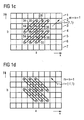
- the inventive method provides to determine a quality measure for at least one further image direction, which differs from the start-Interpolationscardi, which will be explained below with reference to Figure 1c.
- the quality measure is determined as a function of image information values of at least one group of image regions which are arranged adjacent to one another in this image direction.
- six such groups of image regions are formed, which in the example again each comprise the original regions 34-36 and 54-56 arranged around the image region 45 to be interpolated.
- (x, y) is the coordinate of a pixel of this group designated.
- r denotes the observed image direction.
- m denotes the number of pixels that are included in the image direction r group starting from the pixel with the coordinate (x, y), and
- the parameters m, n which determine the number of pixels of a group can be chosen almost arbitrarily, the number of image areas of a group under consideration having the parameters m, n increasing.
- the quality measure for a further image direction is preferably determined -
- the best image direction is the image direction, whose quality measure points to the slightest deviation of pixels arranged next to one another.
- the image direction for which the smallest quality measure was obtained is then selected as the interpolation direction, and for the image area 45 to be interpolated, an image information value is interpolated using those image areas which are adjacent to each other in the interpolation direction.
- ri denotes the interpolation direction determined on the basis of the comparison of the quality measures.
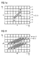
- At least one further iteration step is carried out in which the quality measure for at least one further image direction is determined.
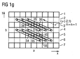
- FIG. 1f shows six groups of pixels, each of which again includes the original pixels 34-36 and 54-56. Each group comprises, in addition to one of these original pixels, two further pixels which lie adjacent to the respective original pixel in the viewed image direction.
- the minimum of these two quality measures M (2,1) and M (-2,1) and the quality measure M (1,1) of the interpolation direction from the preceding iteration step which for the implementation of the current iteration step the start interpolation direction determined to determine a "new" direction of interpolation. If this interpolation direction deviates from the previous interpolation direction, a new interpolation value is determined for the image region 45 to be interpolated, for which purpose image information values of image regions which are arranged adjacent to one another in the new interpolation direction are used.
- the iteration step k-1 is to be carried out for the further image region to be interpolated before carrying out a kth iteration step for the image region to be interpolated, where k is an arbitrary whole number is greater than two. If the individual iteration steps are carried out in parallel for several image areas, it is preferable to use the same iteration steps, i. in iteration steps with the same number, the same image directions examined. For example, in the k-th iteration step for all image regions to be interpolated, the quality measure for the same further image direction is compared with the quality measure for the start-interpolation direction.
- an image direction ri is specified as the first interpolation direction or start-interpolation direction.
- a first interpolation value S (a, b) for the image area to be interpolated is generated by interpolation in this start interpolation direction ri. This interpolation is necessary if the image area to be interpolated is required in the subsequent determination of the quality measures.
- a quality measure for the interpolation direction ri is determined on the basis of image regions in the vicinity of the image region (a, b) to be interpolated.
- a next method step 104 at least one further image direction r, which differs from the interpolation direction ri, is selected and a quality measure for this further image direction r is determined.
- a method step 105 the "best" image direction from the group of the interpolation direction and the at least one image direction is determined by a comparison of the quality measures, and the "best” of these image directions is adopted as the interpolation direction ri.
- an interpolation value for the image area to be interpolated is generated by interpolating the image information values from those image areas which are adjacent to each other in the interpolation direction. If the image should contain additional image regions to be interpolated in addition to the image region to be interpolated, only image regions which are original image regions are preferably used for the interpolation in this process step.
- the further image direction r in method step 104 which differs from the interpolation direction ri, is preferably chosen over all iteration steps so that a new image direction is always used with each iteration step.
- this image direction r selected in method step 104 in addition to the direction of interpolation ri is preferably selected such that an angle between the original interpolation direction selected in method step 101 and the further image direction r considered increases from iteration step to iteration step.
- method step 102 If the image information values of at least one further image area to be interpolated that differs from the image area to be interpolated with the position (a, b) are determined in method step 103 for determining the quality measure M (ri), method step 102 then becomes at least one further Image area applied, ie in the start interpolation direction, an image information value is interpolated to this further image area.
- the method according to the invention is also suitable for the interpolation of more than one intermediate line between two original picture lines.
- Such an interpolation for example, more than one interline is required to scale up or scale a given image.
- the method explained below for interpolating a plurality of intermediate lines is additionally performed in a column direction, ie, a corresponding number of "image columns" are interpolated.
- FIG. 3a shows a detail of an image with three original image lines 1, 3, 5, 7, between each of which more than one, in the example, three, intermediate lines 21-23, 41-43, 61-63 are to be interpolated.
- the method for inter-line interpolation already explained with reference to FIG. 1 can be applied to this reduced image shown in FIG. 3b, taking into account both the position of an image region to be interpolated with respect to the original image regions in the case of low-pass filtering for generating an interpolated image information value and during high-pass filtering is.
- the image information value of the image region, which is closer to the image region to be interpolated is weighted more strongly. This will be explained below with reference to FIG. 3b.
- This group of image areas comprises the original pixel 37 of the original image line 3 and a pixel 416 to be interpolated in the image line 41 to be interpolated and the pixel 218 to be interpolated in the image line 21 to be interpolated.
- These pixels are also shown in FIG. 3a with corresponding reference symbols.
- the image information values of the image areas of this group are high-pass filtered, with the applied high-pass filtering being weighted more strongly by the image areas 416, 218 to be interpolated for the image information value of the image area closer to the original image area 37 lies.
- the image information values of the image regions to be interpolated can be weighted, in particular, proportionally to their distance from the image line of the original image region 37.
- the coefficients of such a high-pass filtering are therefore -1/8, 1/2, -3/8.
- M ' 81 1 ⁇ 1 - c ⁇ S ⁇ 218 + c + d ⁇ S ⁇ 37 - d ⁇ S ⁇ 416 c and d respectively denote the distance between the line with the image area 416 and the line with the image area 37 or the line with the image area 218 and the line with the image area 37.
- an interpolated image information value taking into account the image information values of adjacent original image regions is effected in a correspondingly weighted manner.
- the image information value of the original image area which is closer to the image area to be interpolated, is weighted more.
- the method according to the invention which has been explained with reference to the figures hitherto for an interpolation of interline image pixels is not limited to this application. Rather, the method according to the invention is suitable for the interpolation of arbitrary image information values assigned to individual image-like image areas arranged in an image. The method is also particularly suitable for increasing the resolution of a motion vector field, which will be explained below with reference to FIG.
- FIG. 4a shows a detail of an image which is subdivided into a number of image blocks A-J, to each of which a motion vector Va-Vj is assigned.
- Each of these image blocks has a number of pixels arranged in a matrix-like manner, which is illustrated for the image block A in FIG. 4a by squares shown in dashed lines.
- Motion vectors are required in order to be able to represent motion sequences correctly in the interpolation of intermediate images between two consecutive images of a sequence of images. For the most accurate representation possible of such motion sequences, it is desirable to obtain the highest possible resolution of the motion vector field, d. H. to obtain the smallest possible image blocks, each associated with its own motion vector.
- the image is divided into a second block raster comprising a group of first blocks A1-J1, each completely in the original one Picture blocks AJ of the first grid are included.
- the subdivision of the image takes place initially only in one direction, in the example in the vertical direction, which is again referred to as y-direction. In the horizontal direction, the blocks initially maintain their original width.
- the subdivision into the smaller image blocks of the second block raster results in a group of second image blocks AD-FJ, which are each arranged between two first image blocks A1-J1, and which each overlap two adjacent blocks of the first block raster.
- Each of the image blocks of the second block raster shown in FIG. 4b is preferably of the same size and comprises a number of pixels, which are shown in broken lines for the image block A1 as squares.
- the number of pixels of a block of the second block raster is reduced in the example by a factor of 2 compared to the number of pixels of a block of the first block raster, resulting in an increase of the resolution of the vector field by a factor of 2.
- the first image blocks A1-J1 of the second block raster are each assigned the motion vectors of the image blocks of the first raster, from which they have arisen. These first image blocks A1-J1 form original image areas for carrying out the method according to the invention.
- the second image blocks AD-FJ of the second grid lying in the vertical direction between two such image blocks A1-J1 form image areas to be interpolated for carrying out the method according to the invention.
- Image information values to be interpolated for these image regions AD-FJ to be interpolated are motion vectors, each motion vector comprising two motion vector components, an x-component and a y-component.
- the method according to the invention is thus to be performed twice, namely once for the x-component of the motion vector and once for the y-component of the motion vector.
- the motion vectors Va-Vj of the original image areas are to be subdivided into their motion vector components, wherein in a first implementation of the method, for example, the x-component of the motion vectors of the image areas to be interpolated, only the x-components of the motion vectors of the original image areas are taken into account, and wherein in an interpolation of the y-components of the motion vectors of the image areas to be interpolated only the y-components of the motion vectors of the original image areas are taken into account.
- the interpolated motion vectors for the image areas Ad-Fj to be interpolated which are available after completion of the iterative interpolation method, are shown in dashed lines in FIG. 4b.
- FIG. 4c a further resolution of the motion vector field can be achieved in a next step by subdividing the blocks of the second block raster into smaller blocks in the horizontal direction, as in FIG. 4c for blocks A1, B1, AD, BE, FIG. D1, E1 is shown.
- These smaller blocks form a third block grid.
- This third block grid comprises image blocks which are completely contained in each case in an image block of the second grid and to which the motion vectors of these image blocks of the second block grid are assigned.
- intermediate blocks are formed which are each formed by two blocks of the second block grid arranged adjacent to one another in the horizontal direction.
- These image blocks are designated by the reference symbols A1B1, ADBE, D1E1 in FIG. 4c.
- the blocks which are completely formed by the blocks of the second grid are denoted by the reference symbols A11, B11, AD1, BE1, D11, E11 in FIG. 4c. These last-mentioned picture blocks form original picture areas for carrying out the method according to the invention, while the picture blocks A1B1, ADBE, D1E1 form picture areas to be interpolated.
- the method according to the invention for the interpolation of motion vectors is carried out, the method being performed twice, once for interpolating the x components of the motion vectors, and once for interpolating the y components of the motion vectors.
- each block of the block raster comprises only one pixel, to which a motion vector is then assigned.
- the method according to the invention for interpolating image information values associated with image areas of an image is also suitable for the interpolation of one or more image information values to an image block comprising a plurality of image points arranged in matrix form and for this, for example due to erroneous data transmission, no or incorrect image information values available.
- the application of the method according to the invention to the interpolation of image information values to such an image block is explained below with reference to FIG.
- FIG. 5a shows a detail of an image comprising a multiplicity of pixels arranged in the form of a matrix, which are shown as squares.
- Reference numeral 200 denotes an image block which comprises a number of pixels arranged in the form of a matrix, in the example 4x4 pixels for which no or incorrect image information values are present.
- a single image information value which is assigned to all image points of this image block is first interpolated for this image block 200.
- the pixels of the image in the environment of the image block 200 to be interpolated are merged into image blocks 210-280 which are the same Size as the image block 200 to be interpolated, that is, 4x4 pixels.
- These picture blocks 210-280 are each assigned an image information value, for example by low-pass filtering of the image information values of the individual pixels of these blocks 210-280. These image blocks 210-280 with the image information value assigned to them form original image regions for carrying out the method according to the invention.
- the image block 200 to be interpolated forms an image area to be interpolated for carrying out the method according to the invention.
- the previously explained iterative interpolation process is performed to interpolate an image information value for the image block 200 to be interpolated.
- the resolution of the image block to be interpolated is subsequently increased in order to gradually assign image information values to the individual pixels of this image block. There are various possibilities for this, which are explained below with reference to FIGS. 6 and 7.
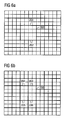
- FIG. 6a it is provided to divide the block 200 in one direction, in the example in the vertical direction, into equally sized sub-blocks 200 to which the image information value of the image block 200 is first assigned as a start interpolation value.
- the pixels in the vicinity of the image block to be interpolated are combined into image blocks of the same size.
- the resulting adjacent image blocks are each assigned an image information value which is formed, for example, by a filtering, in particular a low-pass filtering, of the image information values of the individual pixels of these blocks.
- a filtering in particular a low-pass filtering
- the other of the two blocks as the original picture block when interpolating the picture information value to one of the blocks 201, 202, and to consider this other of the two blocks in the interpolation.
- the image information value of this other image block corresponds to the image information value previously determined for the block 200.
- the implementation of the interpolation method then corresponds to the intermediate line interpolation method explained with reference to FIG. 1, with the difference that in the situation according to FIG. 6a image areas to be interpolated in the image do not repeat regularly.
- the resolution of the block is further increased by a factor of 2 by dividing the block 200 in the horizontal direction, resulting in four image blocks 203, 204, 205, 206.
- the four blocks that have been explained above for the blocks 201, 202 will then be explained Method for interpolating image information values applied.
- the start interpolation values of these image blocks 202-206, which have been formed by subdividing the blocks 201, 202, correspond to the previously interpolated image information value of the block from which they have arisen by subdivision.
- the pixels in the vicinity of the image blocks 203-206 to be interpolated are combined into image blocks of the same size as the image blocks 203-206 to be interpolated. These image blocks form original image areas for performing the iterative interpolation process.
- the method for interpolating the smaller image blocks 203-206 preferably starts with the horizontal direction as start-interpolation direction.
- the direction as the starting interpolation direction in which division of the image block to generate the sub-block has been made is preferable.
- the resolution is increased again by a factor of 2 by subdividing the blocks 203-206 in the vertical direction into subblocks of equal size, one of which is denoted by the reference numeral 207 in FIG. 6c.
- the iterative interpolation method is then applied to each of these subblocks 207, wherein the individual blocks 207 are assigned as start interpolation value the picture information value of that of the blocks 202-206 from which the respective subblock originated.
- the pixels in the vicinity of the overall image block 200 to be interpolated are correspondingly as in the case of FIGS 6a and 6b summarized methods combined into image blocks whose size corresponds to the size of the interpolated sub-blocks.
- the image block to be interpolated comprises 4x4 pixels
- a pixel-by-pixel resolution is achieved.
- the iterative interpolation method is then applied to these individual pixels in order to assign an image information value to each individual pixel.
- the previously determined image information values of the image blocks 207 from which they originated are used as start interpolation values for the individual pixels.
- the resolution of the interpolating image block is successively increased by gradually subdividing the block alternately in the vertical and horizontal directions.
- the image block to be interpolated is divided in one direction, in the example, in the vertical direction into three image blocks, first, second, and third image blocks 210, 211, 212.
- the "width" of the first and third image blocks in the vertical direction is only one pixel, a width of these blocks 210, 212 in the horizontal direction is four pixels in the example.
- an image information value is subsequently obtained using the iterative interpolation method interpolated.
- the pixels of the "middle" image block 211 are treated as original pixels to which the previously determined image information value of the image block 200 is assigned.
- the resolution of the image block is subsequently increased in the horizontal direction, in which the image block is further subdivided in this horizontal direction by forming fourth and fifth image blocks 213, 214, each having a width of one pixel in the horizontal direction have a width of four pixels in the vertical direction.
- fourth and fifth image blocks 213, 214 each having a width of one pixel in the horizontal direction have a width of four pixels in the vertical direction.
- an image information value is subsequently determined using the iterative interpolation method according to the invention.
- the remaining pixels of the image block that is to say the pixels of the reduced image blocks 210 ', 211', 212 ', are treated here as original pixels to which the interpolated image information values of the first, second and third image blocks are assigned.
- a resolution at the pixel level is achieved after carrying out these method steps, while the central image block 211 ', with 2x2 pixels to which only one image information value is assigned, still has a lower resolution.
- This central image block 211 ' will be treated like the original block 200 by increasing its resolution in the horizontal and vertical directions from the edges in "1-pixel increments", respectively.
- the central image block is first subdivided further in the vertical direction so that image blocks 215, 216 each having a width of two and a height of one pixel are formed.
- Each pixel of these image blocks 215, 216 is then applied using the inventive iterative method assigned an image information value.
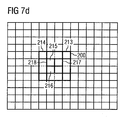
- the image block 211 is then subdivided in the horizontal direction by forming image blocks 217, 218, each having a width of one image block and a height of two pixels, and each of the image points of these image blocks 217, 218 is iterated Assigned an image information value.
- an image information value is interpolated again to the pixels of the blocks 210, 211 which are adjacent to the central region 211 'in the vertical direction.
- pixel-level resolution is achieved for the image block 200 to be originally interpolated.
- the previously explained method can accordingly also be applied to image blocks with more than 4x4 pixels, in each case the resolution being increased from the edges in 1-pixel increments.
- block 200 of FIG. 7 could be subdivided into 8x8 subpixels, of which 2x2 are each associated with a pixel, and interpolated to each of these subpixels a pixel information value.
- the image information value of the respective pixel is formed from the information values of the subpixels associated with a pixel.
- Such a procedure may be particularly useful in order to obtain a satisfactory interpolation result even for a central area, for example the area 211 ', for which the resolution initially remains coarser, when the resolution is increased symmetrically from the edge.
- the quality measure M (r) is determined for at least one further direction of interpolation r
- interpolation values are then mixed in order to obtain the interpolation value S (a, b) used in the further method.
- the weighting factors g1, g2 may be dependent on the difference of the quality measures, for example, such that the interpolation value whose relative direction of interpolation supplies the smaller (better) quality measure is weighted more heavily. The weighting can be the stronger, the greater the difference.
- the quality measure of the hitherto best direction ri which deviates less than the value ⁇ from the quality measure of the direction r, remains stored here in order to be compared in a next iteration step with the quality measure of a further direction r.
- step 118 can optionally be checked in order to provide the direction r, which is newly checked during the respective iteration step, a better quality measure than the comparison direction ri. An interpolation is only performed if this "new" direction yields a better result.
- the interpolation result S (a, b) determined hitherto which may also be a mixture of at least two interpolation results with reference to method step 117, remains stored until a "better" direction is determined.
- condition (14) it is intended to maintain the previous interpolation value obtained by interpolation in direction ri instead of a mixture of two interpolation values S r (a, b), S ri (a, b) perform.
- the method steps 116, 117 are omitted in this alternative method.
- FIG. 9 illustrates such a modified method with reference to the signal flow diagram, wherein only the method steps modified with respect to the methods explained so far are illustrated.
- a filtering is carried out which takes into account the best interpolation direction of the current image area in the past, taking into account the best interpolation direction ri and the method step 106 in which interpolation is performed the filtered until then determined best interpolation directions of adjacent image areas.
- ri' f ri ⁇ ri 1 ...
- ri n where ri 'is the filtered interpolation direction, ri is the best interpolation direction for a given image area, ri 1 ... ri n is the best interpolation directions of adjacent image areas, and f (.) is a filter function.
- This filtering can be done during each iteration step. In addition, it is also possible to perform this filtering only once at the end of the iteration process if the best interpolation direction exists for each image area.
- These best interpolation directions are then filtered to obtain filtered interpolation directions before final interpolation in the filtered interpolation directions.
- the filtering which assigns a filtered interpolation direction ri 'to the current image area 500 having the hitherto best interpolation direction ri is, for example, a median filtering supplied with the interpolation direction of the current area and the interpolation directions of the eight surrounding areas and the median of these total of nine interpolation directions outputs as a filtered interpolation direction.
- a filtering of the other direction component of the image directions is sufficient.
- the interpolation directions of the image areas can still be updated during the filtering, so that possibly already filtered interpolation directions are used during the filtering of further image areas during a filter pass.
- the filter result may, however, be dependent on the order in which filtered interpolation directions are determined for the individual image regions. If this dependency is to be avoided, in the determination of filtered interpolation directions to a group of image areas, only the first, i. taken into account before the filter pass, interpolation directions.
- the filtered interpolation direction ri 'obtained in the manner explained above is adopted as the best interpolation direction for the current image area (step 120) and based on the interpolation in method step 106.
- image regions 501-508 surrounding the image region 500 to be interpolated can also be original image regions for which image information is already present.
- Such original image areas can be identified with the same iterative process steps, with where an interpolation direction is determined for an image area to be interpolated, interpolation directions are determined, which are subsequently used for the filtering.
- the interpolation direction assigned to each image region of a current image at the end of the iteration process, ie after the end condition has been satisfied in method step 107, is "temporally filtered" prior to the execution of a final interpolation.
- at least one interpolation direction is used for this, which is assigned to an image area in at least one temporally adjacent image of the current image, which is located at the same position as the current image area.
- ri denotes a best interpolation direction determined for the image area of the current image after completion of all iteration steps.
- ri t-1 denotes the best interpolation direction for an image region of a temporally adjacent image after completion of all iteration steps, which in this image is at the same local position as the current one Image area is located in the current image. This procedure is illustrated in FIG.
- the reference numeral 310 designates a current picture and the reference numerals 320 and 330 designate two pictures temporally adjacent to the current picture.
- the reference numerals 311, 321, 331 denote image areas at the same local positions in the individual images, to which respective interpolation directions are assigned, which were determined by the iterative method explained above.
- an interpolation direction is used which results from filtering the interpolation directions of the image areas which are located locally at the same position, but in temporal succession.
Landscapes
- Engineering & Computer Science (AREA)
- Computer Graphics (AREA)
- Multimedia (AREA)
- Signal Processing (AREA)
- Physics & Mathematics (AREA)
- General Physics & Mathematics (AREA)
- Theoretical Computer Science (AREA)
- Television Systems (AREA)
- Image Processing (AREA)
Applications Claiming Priority (1)
| Application Number | Priority Date | Filing Date | Title |
|---|---|---|---|
| DE102005046772A DE102005046772A1 (de) | 2005-09-29 | 2005-09-29 | Iteratives Verfahren zur Interpolation von Bildinformationswerten |
Publications (2)
| Publication Number | Publication Date |
|---|---|
| EP1770635A1 true EP1770635A1 (fr) | 2007-04-04 |
| EP1770635B1 EP1770635B1 (fr) | 2009-04-08 |
Family
ID=37654972
Family Applications (1)
| Application Number | Title | Priority Date | Filing Date |
|---|---|---|---|
| EP06020428A Not-in-force EP1770635B1 (fr) | 2005-09-29 | 2006-09-28 | Méthode itérative d'interpolation d'image |
Country Status (3)
| Country | Link |
|---|---|
| US (1) | US7843509B2 (fr) |
| EP (1) | EP1770635B1 (fr) |
| DE (2) | DE102005046772A1 (fr) |
Families Citing this family (14)
| Publication number | Priority date | Publication date | Assignee | Title |
|---|---|---|---|---|
| JP4181598B2 (ja) * | 2006-12-22 | 2008-11-19 | シャープ株式会社 | 画像表示装置及び方法、画像処理装置及び方法 |
| US7783134B2 (en) * | 2007-01-04 | 2010-08-24 | Himax Technologies Limited | Edge-oriented interpolation method and system for a digital image |
| DE102007015002A1 (de) | 2007-03-28 | 2008-10-02 | Micronas Gmbh | Iteratives Verfahren zur Interpolation von Bildinformationswerten |
| JP4846644B2 (ja) * | 2007-03-30 | 2011-12-28 | 株式会社東芝 | 映像信号補間装置および映像信号補間方法 |
| US8237859B2 (en) * | 2007-09-14 | 2012-08-07 | Himax Technologies Limited | Method for video conversion of video stream and apparatus thereof |
| FR2925199A1 (fr) * | 2007-12-13 | 2009-06-19 | Thomson Licensing Sas | Procede de generation de distances representatives d'orientations de contour dans une image video, dispositif correspondant et utilisation du procede pour le desentrelacement ou la conversion de format |
| US20090262249A1 (en) * | 2008-04-22 | 2009-10-22 | Himax Media Solutions, Inc. | Interpolated frame generating method |
| EP2114068A1 (fr) * | 2008-04-30 | 2009-11-04 | Sony Corporation | Procédé de conversion d'une image et unité de conversion d'images |
| DE102008048257B4 (de) * | 2008-09-22 | 2012-02-09 | Trident Microsystems (Far East) Ltd. | Verfahren zur Detektion eines Blockrasters |
| TW201037629A (en) * | 2009-04-14 | 2010-10-16 | Novatek Microelectronics Corp | Interpolation method and interpolation circuit |
| TWI399703B (zh) * | 2009-12-02 | 2013-06-21 | Micro Star Int Co Ltd | 往返縮放之影像放大方法 |
| US9659353B2 (en) * | 2010-03-01 | 2017-05-23 | Stmicroelectronics, Inc. | Object speed weighted motion compensated interpolation |
| GB201117191D0 (en) | 2011-10-04 | 2011-11-16 | Imagination Tech Ltd | +Detecting image impairments in an interpolated image |
| DE102018216413A1 (de) * | 2018-09-26 | 2020-03-26 | Robert Bosch Gmbh | Vorrichtung und Verfahren zur automatischen Bildverbesserung bei Fahrzeugen |
Citations (3)
| Publication number | Priority date | Publication date | Assignee | Title |
|---|---|---|---|---|
| DE4407101A1 (de) * | 1994-03-03 | 1995-09-14 | Siemens Ag | Verfahren zur Formatkonversion von in einem ersten Bildpunktraster vorliegenden Bildsequenzen in ein zweites Bildpunktraster |
| US20040257467A1 (en) * | 2003-02-19 | 2004-12-23 | Stmicroelectronics Sa | Process and device for de-interlacing by pixel analysis |
| US20050134730A1 (en) * | 2003-12-23 | 2005-06-23 | Lsi Logic Corporation | Method and apparatus for video deinterlacing and format conversion |
Family Cites Families (11)
| Publication number | Priority date | Publication date | Assignee | Title |
|---|---|---|---|---|
| EP0466981B1 (fr) * | 1990-07-20 | 1997-02-26 | Koninklijke Philips Electronics N.V. | Dispositif de traitement de vecteurs mouvement |
| FI93295C (fi) * | 1992-08-25 | 1995-03-10 | Salon Televisiotehdas Oy | Menetelmä ja kytkentä videosignaalin pysty- ja vaakataajuuden kaksinkertaistamiseksi |
| DE69605018T2 (de) * | 1996-02-13 | 2000-06-08 | Stmicroelectronics S.R.L., Agrate Brianza | Kantenorientiertes Intrabild- und Zwischenbildinterpolationsfilter für Videogeräte besserer Qualität |
| JPH10187089A (ja) * | 1996-12-26 | 1998-07-14 | Canon Inc | 表示制御装置及び表示制御方法 |
| US6229570B1 (en) * | 1998-09-25 | 2001-05-08 | Lucent Technologies Inc. | Motion compensation image interpolation—frame rate conversion for HDTV |
| US6731342B2 (en) * | 2000-01-06 | 2004-05-04 | Lg Electronics Inc. | Deinterlacing apparatus and method using edge direction detection and pixel interplation |
| US20030218621A1 (en) * | 2002-05-24 | 2003-11-27 | Jiande Jiang | Method and system for edge-adaptive interpolation for interlace-to-progressive conversion |
| DE10232372B3 (de) * | 2002-07-17 | 2004-01-22 | Micronas Gmbh | Verfahren zur Interpolation eines Bildpunktes einer Zwischenzeile eines Halbbildes |
| DE10236207A1 (de) * | 2002-08-07 | 2004-02-26 | Micronas Gmbh | Verfahren zur bewegungsvektorgestützten Interpolation eines Bildpunktes eines Zwischenbildes einer Bildfolge |
| KR100568105B1 (ko) * | 2003-10-02 | 2006-04-05 | 삼성전자주식회사 | 에지 기반의 영상 적응형 디인터레이싱 방법 |
| KR100540380B1 (ko) * | 2004-01-06 | 2006-01-12 | 이디텍 주식회사 | 디인터레이서의 필드 내 보간 장치 및 그 방법 |
-
2005
- 2005-09-29 DE DE102005046772A patent/DE102005046772A1/de not_active Ceased
-
2006
- 2006-09-28 DE DE502006003367T patent/DE502006003367D1/de active Active
- 2006-09-28 US US11/540,484 patent/US7843509B2/en not_active Expired - Fee Related
- 2006-09-28 EP EP06020428A patent/EP1770635B1/fr not_active Not-in-force
Patent Citations (3)
| Publication number | Priority date | Publication date | Assignee | Title |
|---|---|---|---|---|
| DE4407101A1 (de) * | 1994-03-03 | 1995-09-14 | Siemens Ag | Verfahren zur Formatkonversion von in einem ersten Bildpunktraster vorliegenden Bildsequenzen in ein zweites Bildpunktraster |
| US20040257467A1 (en) * | 2003-02-19 | 2004-12-23 | Stmicroelectronics Sa | Process and device for de-interlacing by pixel analysis |
| US20050134730A1 (en) * | 2003-12-23 | 2005-06-23 | Lsi Logic Corporation | Method and apparatus for video deinterlacing and format conversion |
Also Published As
| Publication number | Publication date |
|---|---|
| EP1770635B1 (fr) | 2009-04-08 |
| DE502006003367D1 (de) | 2009-05-20 |
| US7843509B2 (en) | 2010-11-30 |
| US20070236601A1 (en) | 2007-10-11 |
| DE102005046772A1 (de) | 2007-04-05 |
Similar Documents
| Publication | Publication Date | Title |
|---|---|---|
| DE69812882T2 (de) | Verfahren zur bewegungskompensierten Mehrhalbbildverbesserung von Videostandbildern | |
| DE69131591T2 (de) | Bewegungsabhängige Videosignalverarbeitung | |
| DE69031055T2 (de) | Bewegungsabhängige Videosignalverarbeitung | |
| DE69027479T2 (de) | Bewegungsabhängige Videosignalverarbeitung | |
| EP1770635B1 (fr) | Méthode itérative d'interpolation d'image | |
| DE69021431T2 (de) | Bewegungsabhängige Videosignalverarbeitung. | |
| DE69028651T2 (de) | Bewegungsabhängige Videosignalverarbeitung | |
| DE69431791T2 (de) | Vorrichtung und verfahren zur automatischen bildentzerrung | |
| DE69028792T2 (de) | Bewegungsabhängige Videosignalverarbeitung | |
| DE69423166T2 (de) | Verfahren und Vorrichtung zur Bewegungsauswertung mit Blockübereinstimmung | |
| DE69031144T2 (de) | Bewegungsabhängige Videosignalverarbeitung | |
| DE102004017145B4 (de) | Verfahren und Vorrichtung zur Ermittlung von Bewegungvektoren, die Bildbereichen eines Bildes zugeordnet sind | |
| DE69031322T2 (de) | Bewegungsabhängige Videosignalverarbeitung | |
| DE4407101A1 (de) | Verfahren zur Formatkonversion von in einem ersten Bildpunktraster vorliegenden Bildsequenzen in ein zweites Bildpunktraster | |
| EP0897247A2 (fr) | Procédé de calcul de vecteurs de mouvement | |
| EP1634245A2 (fr) | Procede de determination d'un vecteur de deplacement dans le traitement d'images | |
| EP1976288B1 (fr) | Procédé itératif destiné à l'interpolation de valeurs d'informations d'image | |
| EP2105883A1 (fr) | Procédé destiné au test d'un vecteur de mouvement | |
| EP1489842B1 (fr) | Procédé et appareil d'interpolation des éléments d'image en fonction du vecteur de mouvement | |
| EP1605405B1 (fr) | Procédé pour la détermination des vecteurs de mouvement | |
| DE102009026983A1 (de) | Bildverarbeitungsverfahren mit einer Bewegungsschätzung und Bildverarbeitungsanordnung | |
| EP1397002B1 (fr) | Procédé d'interpolation des éléments d'image en fonction du gradient | |
| DE102005063072B4 (de) | Verfahren und Vorrichtung zur Zwischenzeileninterpolation | |
| DE102016209662A1 (de) | Verfahren und Vorrichtung zum Bestimmen eines Übergangs zwischen zwei Anzeigebildern, und Fahrzeug | |
| EP0727904A2 (fr) | Méthode et arrangement de circuit pour la réduction de scintillation dans un dispositif de traitement de signal vidéo |
Legal Events
| Date | Code | Title | Description |
|---|---|---|---|
| PUAI | Public reference made under article 153(3) epc to a published international application that has entered the european phase |
Free format text: ORIGINAL CODE: 0009012 |
|
| AK | Designated contracting states |
Kind code of ref document: A1 Designated state(s): AT BE BG CH CY CZ DE DK EE ES FI FR GB GR HU IE IS IT LI LT LU LV MC NL PL PT RO SE SI SK TR |
|
| AX | Request for extension of the european patent |
Extension state: AL BA HR MK YU |
|
| 17P | Request for examination filed |
Effective date: 20070320 |
|
| AKX | Designation fees paid |
Designated state(s): DE FR GB IT NL |
|
| GRAP | Despatch of communication of intention to grant a patent |
Free format text: ORIGINAL CODE: EPIDOSNIGR1 |
|
| GRAS | Grant fee paid |
Free format text: ORIGINAL CODE: EPIDOSNIGR3 |
|
| GRAA | (expected) grant |
Free format text: ORIGINAL CODE: 0009210 |
|
| AK | Designated contracting states |
Kind code of ref document: B1 Designated state(s): DE FR GB IT NL |
|
| REG | Reference to a national code |
Ref country code: GB Ref legal event code: FG4D Free format text: NOT ENGLISH |
|
| REF | Corresponds to: |
Ref document number: 502006003367 Country of ref document: DE Date of ref document: 20090520 Kind code of ref document: P |
|
| PLBE | No opposition filed within time limit |
Free format text: ORIGINAL CODE: 0009261 |
|
| STAA | Information on the status of an ep patent application or granted ep patent |
Free format text: STATUS: NO OPPOSITION FILED WITHIN TIME LIMIT |
|
| 26N | No opposition filed |
Effective date: 20100111 |
|
| REG | Reference to a national code |
Ref country code: NL Ref legal event code: SD Effective date: 20101011 |
|
| REG | Reference to a national code |
Ref country code: GB Ref legal event code: 732E Free format text: REGISTERED BETWEEN 20101125 AND 20101201 |
|
| REG | Reference to a national code |
Ref country code: FR Ref legal event code: TP |
|
| REG | Reference to a national code |
Ref country code: DE Ref legal event code: R081 Ref document number: 502006003367 Country of ref document: DE Owner name: ENTROPIC COMMUNICATIONS, INC., SAN DIEGO, US Free format text: FORMER OWNER: MICRONAS GMBH, 79108 FREIBURG, DE Effective date: 20110210 |
|
| REG | Reference to a national code |
Ref country code: DE Ref legal event code: R084 Ref document number: 502006003367 Country of ref document: DE Effective date: 20110426 |
|
| REG | Reference to a national code |
Ref country code: DE Ref legal event code: R082 Ref document number: 502006003367 Country of ref document: DE Representative=s name: EPPING HERMANN FISCHER, PATENTANWALTSGESELLSCH, DE |
|
| REG | Reference to a national code |
Ref country code: DE Ref legal event code: R082 Ref document number: 502006003367 Country of ref document: DE Representative=s name: EPPING HERMANN FISCHER, PATENTANWALTSGESELLSCH, DE Effective date: 20121119 Ref country code: DE Ref legal event code: R081 Ref document number: 502006003367 Country of ref document: DE Owner name: ENTROPIC COMMUNICATIONS, INC., US Free format text: FORMER OWNER: TRIDENT MICROSYSTEMS (FAR EAST) LTD., GRAND CAYMAN, KY Effective date: 20121119 Ref country code: DE Ref legal event code: R081 Ref document number: 502006003367 Country of ref document: DE Owner name: ENTROPIC COMMUNICATIONS, INC., SAN DIEGO, US Free format text: FORMER OWNER: TRIDENT MICROSYSTEMS (FAR EAST) LTD., GRAND CAYMAN, KY Effective date: 20121119 Ref country code: DE Ref legal event code: R082 Ref document number: 502006003367 Country of ref document: DE Representative=s name: EPPING HERMANN FISCHER PATENTANWALTSGESELLSCHA, DE Effective date: 20121119 |
|
| PGFP | Annual fee paid to national office [announced via postgrant information from national office to epo] |
Ref country code: NL Payment date: 20120924 Year of fee payment: 7 |
|
| REG | Reference to a national code |
Ref country code: GB Ref legal event code: 732E Free format text: REGISTERED BETWEEN 20131107 AND 20131113 |
|
| REG | Reference to a national code |
Ref country code: FR Ref legal event code: TP Owner name: ENTROPIC COMMUNICATIONS, INC., US Effective date: 20131119 |
|
| REG | Reference to a national code |
Ref country code: NL Ref legal event code: V1 Effective date: 20140401 |
|
| PG25 | Lapsed in a contracting state [announced via postgrant information from national office to epo] |
Ref country code: NL Free format text: LAPSE BECAUSE OF NON-PAYMENT OF DUE FEES Effective date: 20140401 |
|
| PGFP | Annual fee paid to national office [announced via postgrant information from national office to epo] |
Ref country code: FR Payment date: 20140917 Year of fee payment: 9 Ref country code: GB Payment date: 20140929 Year of fee payment: 9 |
|
| PGFP | Annual fee paid to national office [announced via postgrant information from national office to epo] |
Ref country code: IT Payment date: 20140923 Year of fee payment: 9 |
|
| PG25 | Lapsed in a contracting state [announced via postgrant information from national office to epo] |
Ref country code: IT Free format text: LAPSE BECAUSE OF NON-PAYMENT OF DUE FEES Effective date: 20150928 |
|
| GBPC | Gb: european patent ceased through non-payment of renewal fee |
Effective date: 20150928 |
|
| REG | Reference to a national code |
Ref country code: FR Ref legal event code: ST Effective date: 20160531 |
|
| PG25 | Lapsed in a contracting state [announced via postgrant information from national office to epo] |
Ref country code: GB Free format text: LAPSE BECAUSE OF NON-PAYMENT OF DUE FEES Effective date: 20150928 |
|
| PG25 | Lapsed in a contracting state [announced via postgrant information from national office to epo] |
Ref country code: FR Free format text: LAPSE BECAUSE OF NON-PAYMENT OF DUE FEES Effective date: 20150930 |
|
| PGFP | Annual fee paid to national office [announced via postgrant information from national office to epo] |
Ref country code: DE Payment date: 20160928 Year of fee payment: 11 |
|
| REG | Reference to a national code |
Ref country code: DE Ref legal event code: R119 Ref document number: 502006003367 Country of ref document: DE |
|
| PG25 | Lapsed in a contracting state [announced via postgrant information from national office to epo] |
Ref country code: DE Free format text: LAPSE BECAUSE OF NON-PAYMENT OF DUE FEES Effective date: 20180404 |