EP1772879B1 - Steuerungssystem und Handprogrammiergerät für einen Industrieroboter - Google Patents
Steuerungssystem und Handprogrammiergerät für einen Industrieroboter Download PDFInfo
- Publication number
- EP1772879B1 EP1772879B1 EP05027996A EP05027996A EP1772879B1 EP 1772879 B1 EP1772879 B1 EP 1772879B1 EP 05027996 A EP05027996 A EP 05027996A EP 05027996 A EP05027996 A EP 05027996A EP 1772879 B1 EP1772879 B1 EP 1772879B1
- Authority
- EP
- European Patent Office
- Prior art keywords
- robot
- safety switch
- switch
- switches
- tpu
- Prior art date
- Legal status (The legal status is an assumption and is not a legal conclusion. Google has not performed a legal analysis and makes no representation as to the accuracy of the status listed.)
- Expired - Lifetime
Links
Images


Classifications
-
- H—ELECTRICITY
- H01—ELECTRIC ELEMENTS
- H01H—ELECTRIC SWITCHES; RELAYS; SELECTORS; EMERGENCY PROTECTIVE DEVICES
- H01H9/00—Details of switching devices, not covered by groups H01H1/00 - H01H7/00
- H01H9/02—Bases, casings, or covers
- H01H9/0214—Hand-held casings
-
- B—PERFORMING OPERATIONS; TRANSPORTING
- B25—HAND TOOLS; PORTABLE POWER-DRIVEN TOOLS; MANIPULATORS
- B25J—MANIPULATORS; CHAMBERS PROVIDED WITH MANIPULATION DEVICES
- B25J13/00—Controls for manipulators
- B25J13/02—Hand grip control means
-
- B—PERFORMING OPERATIONS; TRANSPORTING
- B25—HAND TOOLS; PORTABLE POWER-DRIVEN TOOLS; MANIPULATORS
- B25J—MANIPULATORS; CHAMBERS PROVIDED WITH MANIPULATION DEVICES
- B25J13/00—Controls for manipulators
- B25J13/06—Control stands, e.g. consoles, switchboards
- B25J13/065—Control stands, e.g. consoles, switchboards comprising joy-sticks
-
- B—PERFORMING OPERATIONS; TRANSPORTING
- B25—HAND TOOLS; PORTABLE POWER-DRIVEN TOOLS; MANIPULATORS
- B25J—MANIPULATORS; CHAMBERS PROVIDED WITH MANIPULATION DEVICES
- B25J19/00—Accessories fitted to manipulators, e.g. for monitoring, for viewing; Safety devices combined with or specially adapted for use in connection with manipulators
- B25J19/06—Safety devices
-
- H—ELECTRICITY
- H01—ELECTRIC ELEMENTS
- H01H—ELECTRIC SWITCHES; RELAYS; SELECTORS; EMERGENCY PROTECTIVE DEVICES
- H01H3/00—Mechanisms for operating contacts
- H01H3/02—Operating parts, i.e. for operating driving mechanism by a mechanical force external to the switch
- H01H3/0253—Operating parts, i.e. for operating driving mechanism by a mechanical force external to the switch two co-operating contacts actuated independently
-
- H—ELECTRICITY
- H01—ELECTRIC ELEMENTS
- H01H—ELECTRIC SWITCHES; RELAYS; SELECTORS; EMERGENCY PROTECTIVE DEVICES
- H01H9/00—Details of switching devices, not covered by groups H01H1/00 - H01H7/00
- H01H2009/0083—Details of switching devices, not covered by groups H01H1/00 - H01H7/00 using redundant components, e.g. two pressure tubes for pressure switch
-
- H—ELECTRICITY
- H01—ELECTRIC ELEMENTS
- H01H—ELECTRIC SWITCHES; RELAYS; SELECTORS; EMERGENCY PROTECTIVE DEVICES
- H01H2217/00—Facilitation of operation; Human engineering
- H01H2217/048—Facilitation of operation; Human engineering adapted for operation by left- and right-handed
-
- H—ELECTRICITY
- H01—ELECTRIC ELEMENTS
- H01H—ELECTRIC SWITCHES; RELAYS; SELECTORS; EMERGENCY PROTECTIVE DEVICES
- H01H3/00—Mechanisms for operating contacts
- H01H3/02—Operating parts, i.e. for operating driving mechanism by a mechanical force external to the switch
- H01H3/022—Emergency operating parts, e.g. for stop-switch in dangerous conditions
Definitions
- the invention relates to a control system for an industrial robot of the kind comprising a portable robot controller or teach pendant for manually controlling movement of a robot or manipulator arm.
- the invention relates to a hand operated safety switch according to the preamble of claim 1 for safe use of a robot or other machine under manual control.
- a safety switch is known from EP-A-1229562 .
- a memory means in the control system may store the coordinates of said set points as position instructions and other operating instructions which, together with said set points, may define a work cycle of the robot and means arranged, during automatic running of the robot, to control the robot in accordance with information stored in the memory means during the programming stage.
- the robot during programming is often run with the aid of a first control means which can be manually influenced, a means such as a joystick.
- the joystick is often comprised in a portable control unit also called a Teach Pendant Unit or TPU.
- the robot or end effector of the robot is successively moved to each of said set points or waypoints which define the movement path or the operating positions that the robot is to follow or assume during automatic operation.
- These positions may be stored in the form of a sequence of position instructions in a program memory, i.e. the memory means, present in the robot, or in a control unit.
- other operating instructions are stored in the program memory giving further information about the working cycle of the robot.
- the operating instructions may give information about the desired robot velocity in a certain section of the movement, about control of outputs from the robot to external equipment, about a desired precision of the robot movement, about conditions for the robot movement in dependence on input signals from external sensors or equipments, about events such as switch on/off paint spray, about calls for pre-programmed subroutines, and so on.
- the program instructions are run through successively, and the robot is displaced successively between the different programmed positions in accordance with the position instructions and further carries out the measures which are programmed into the instructions.
- Control system for an industrial robot describes a portable unit or teach pendant unit for manual control of the robot during programming for teaching the robot to follow a trajectory or working path defined by a number of set points.
- the TPU described comprises a joystick arranged for controlling the movement of the robot as well as other control means with a plurality of other control functions.
- a control unit or TPU for use with robot must include a safety switch of the type known as a dead man's handle or also known as a live handle switch. This device requires the operator to hold a switch in a run position such that if the operator lets go of the switch, the machine stops.
- a live handle switch of a TPU may comprise a certified safety switch type as described in US 5,444,203 to Gunnarsson assigned to ABB entitled Safety switch for an Industrial Machine. The above specification describes a three position safety switch, which is operable from a first end position via an operating position to a second end position, the safety circuit being closed (made) only in the operating position.
- EP1229562 discloses, especially in figures 31 and 32, a TPU comprising a safety switch in form of a push button.
- the push button is stationary and it is actuated by two manipulation lever members movable by right and left hand, respectively.
- the present invention aims to provide an improved safety switch for a control system for an industrial robot of the kind mentioned above.
- the present invention provides a safety switch as defined in claim 1.
- the improved live handle switch is provided arranged to control robot movement so as to stop movement in the event that the operator does not hold the live handle switch in a run position.
- the live handle switch is arranged connected to a first and a second safety switch operating means arranged such that the robot may be moved if one safety switch operating means only is held in the run position, and such that robot movement stops if neither safety switch operating means is held in the run position.
- the live handle switch is arranged connected to a first and a second safety switch operating means arranged such that the robot may not be moved if any one of two safety switch operating means is urged or held in a panic stop position.
- a portable robot control wherein the controller or TPU comprises an improved live handle switch according to an embodiment of the invention and complying with an industrial safety standard arranged to control robot movement so as to stop movement in the event that the operator does not hold the live handle switch in a run position.
- the live handle switch is arranged connected to a first and a second safety switch operating means arranged such that the robot may be moved if one safety switch operating means only is held in the a run position, and such that robot movement stops if neither safety switch operating means is held in the run position.
- a very significant advantage of the improved safety switch according to the invention is provided by comprising a safety means arranged to permit an operator to operate the robot controller using one hand only. This is also a feature that provides opportunities to reduce operator fatigue. This also permits a changeover of operation from one hand to the other hand such that control of the robot does not have to be interrupted.
- the safety arrangement provides two live handle switch operating means, one being located within reach of the left hand and the other one within reach of the right hand. The operator can hold one first live handle switch operating means in one hand, grip the second live handle switch operating means with the other hand, and then let go of the first live handle switch operating means, and control the robot with the second means. By doing so the operator can change hands or take away either hand from the TPU without interrupting control.
- the above new features of improved TPU offer considerably improved ease-of-use for an operator and also contributes to significant reductions in operator fatigue.
- a further advantage of the improved live handle switch is that it provides for two handed operation and yet still retains the robust logic of a single-handed safety switch.
- Another advantage of the improved live handle switch according to the invention is that the established logical operations of an existing double set of certified safety switches can be used as they are now. New certification is not necessary. For example there may also be a built-in feature that will disable re-connection after panic break until the switches have been fully released.
- Another advantage of the improved live handle switch is that it is robust and simple compared to a possible solution based on more than one set of switches arranged in parallel, which would introduce a number of new logical (connection) case combinations to be resolved.
- a robot controller comprising an improved live handle switch according to the invention proposes a new way for safely operating a robot under manual control.
- the effort required to program a robot is reduced because the movement control task may be shared between two hands as required.
- the improved live handle switch may be incorporated in other devices for controlling machines while under manual control.
- Providing safety switch devices with improved ease of use means a wider range of control and programming or configuration options is available.
- Figure 1 shows an improved live handle switch with two actuating handles according to an embodiment of the invention. It shows the live handle switch 1 and an enclosing housing.
- Two safe switches 4a, 4b are arranged beside each other in the switch mechanism and connected in parallel. Each switch includes a movable part 9a, 9b, which parts when urged into the switch, in the direction R from left to right in the diagram, then actuate or switch each of the two switches more or less simultaneously.
- Safe switches 4a, 4b are arranged mounted on a first moveable member 2.
- a second movable member 5 is arranged relative first member 2 so that either member may be urged and moved in the left or right direction independently of the other.
- Figure 2 is a view of the underside of the live handle switch. It shows the first member 2 with a view of the safe switches 4 arranged on it. The second member 5 is shown arranged relative to first member 2.
- the first member 2 may be urged in the left direction L by an operator pressing on an actuating handle 6L.
- the second movable member 5 may be urged to the right hand side direction R by an operator pressing on an actuating handle 6R in a direction to the right.
- the actuating "button" 9a, 9b of the two safe switches 4a, 4b are urged to the right and the switch is actuated (see also additional details on typical switching sequences below).
- the identical result is produced when an operator urges the left actuating handle 6L to the left.
- handle 6L and first member 2 are urged to the left, the switches mounted on first member 2 are urged from right to left against second member 5, and the switches are thus actuated.
- FIG. 3a-3e illustrates the operating positions that are typically available. These may be summarised as:
- one set of certified double live handle switches is operated using double mechanical live handles.
- the operator grip can be shifted from one hand to the other without breaking the circuit, but both sides cannot be operated simultaneously.
- this is effectively and efficiently accomplished by attaching the double set of switches to one of the actuators so they are located in between the two moveable members, one from each left and right live handle part.
- the improved live handle switch is comprised in a robot control unit or Teach Pendant Unit, TPU.
- the live handle switch may comprise a certified safety switch type as described in US 5,444,203 to Gunnarsson assigned to ABB entitled Safety Switch for an Industrial Machine.
- the above specification describes a three position safety switch, which specification is hereby incorporated in this description in full by means of this reference.
- the safety switch is operable from a first end position via an operating position to a second end position, the safety circuit being closed (made) only in the operating position. During the return movement from second position to the first end position, the contact device is not affected, and the safety circuit thus remains open during the whole of this return movement.
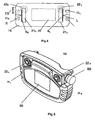
- FIG. 5 shows a view in 3D of a TPU comprising an improved live handle switch according to an embodiment of the invention.
- This TPU also comprises two joysticks 22 L , 22 R
- the TPU shown has on the upper side a display screen 20 and an emergency stop button ES. It is arranged to be held using one or both handgrips, H R and/or H L .
- FIG. 4 shows a schematic view from below of a TPU comprising an improved live handle switch according to an embodiment of the invention.
- the figure shows a TPU in the form of a panel 15 or console.
- An emergency stop button ES is arranged as a push button on a part of the panel.
- the TPU is also shown formed with a handgrip pattern on two sides.
- the handgrip patterns on the TPU are advantageous to make it more comfortable for the operator to grip and hold the TPU.
- An operator normally holds the TPU that is shown in Figure 4 by holding the left handgrip H L in the left hand and right handgrip H R in the right hand.
- the panel is preferably further arranged on the top side with a display 20 of some sort and one or more switch means (not shown).
- the switch means may be arranged as single pushbuttons or groups of pushbuttons. The functions of the pushbuttons are controlled by the robot control system and may be presented in plain text on the display. Generally each pushbutton when activated displays to the operator information about what measures are permitted at each moment.
- One or two control means 22 L , 22 R preferably a joystick, is/are mounted on the top side with its vertical axis perpendicular to the panel. It may be moved or manually influenced in a direction that may be represented as a movement with two degrees of freedom.
- the second control means may, if it also is a joystick, also be moved or manually influenced in a direction that may be representing a movement with up to two degrees of freedom.
- one direction may be configured to control or move the robot in a vertical or z axis direction, even though in real time the operator also moves the second joystick generally in an x or y direction.
- On the underside of the panel are arranged two recesses 21 L and 21 R .
- Two handles, 6 L , 6 R which actuate the live handle switch inside the enclosing panel or console are arranged in the recesses.
- At least one of the live handle switch operating means handles 6 L , 6 R arranged to operate the safety switch may be regarded as a form of enabling device within the context of robot control, and portable robot control units in particular.
- the operator may hold the TPU in, say, the left hand about handgrip H L and at the same time press the safety switch operating handle 6 L substantially in the direction indicated L with fingers of the same hand, so holding the live handle in the run position, and capable of moving further left to the panic position.
- the operator may also operate a joystick 22 L on the top of the panel by using the left thumb.
- the right hand may be free, the right hand may hold the TPU, or the right hand may hold the TPU and operate one or more buttons or controls such as a right joystick 22 R .
- the operator can also hold the TPU in the right hand and then remove the left hand as soon as the fingers of the right hand have pressed the safety switch operating means 6 R , for example in the right direction R. That is to say that so long as one of the safety switch operating means 6 L or 6 R is held in a connection position L O or R O by the operator the robot can be moved.
- the great advantage of the improved TPU is that the operator can operate the TPU with one hand, hold the TPU in one hand and then change it to the other hand without stopping movement control of the robot.
- the TPU comprising an improved live handle switch may be used to program and control an industrial robot or manipulator arm to carry out one or more of many tasks, including any task from the list of: gripping an object, manipulating an object, stacking, pick and place objects, controlling and operating an amusement ride or an installation comprising a human passenger, welding, framing a vehicle body, riveting, de-burring, fettling, grinding, coating, painting, applying sealant, applying glue, dry spraying, gluing, folding plate, bending plate, hemming plate.
- Plainly mechanical handles may be arranged to be urged in opposite directions to one another along another axis, one up and one down for example.
- the safety switch operating means 6 L or 6 R may be urged in another direction than L or R in order to enable use of the TPU.
- an improved live handle switch may be arranged to operate a safety device used for operations with machines and especially robots.
- Robots and other machinery in an enclosed working area or cell may be arranged with safety switches to prevent machinery from operating if, for example, a gate of the cell is open.
- a personal safety switch comprising an improved live handle according to any embodiment. The operator can thus hold a switch by one of two mechanical actuating handles and subsequently change control over and use the other hand as required, thus reducing fatigue and improving flexibility.
Landscapes
- Engineering & Computer Science (AREA)
- Robotics (AREA)
- Mechanical Engineering (AREA)
- Manipulator (AREA)
- Numerical Control (AREA)
Claims (9)
- Ein handbedienter Sicherheitsschalter für einen Industrieroboter oder eine Industriemaschine, wobei der Sicherheitsschalter zwei parallel verbundene sichere Schalter (4, 4a, 4b) umfasst, wobei die sicheren Schalter (4, 4a, 4b) mit einem ersten und einem zweiten beweglichen Element (2, 5) angeordnet sind, so dass die sicheren Schalter (4, 4a, 4b) durch Drängen entweder des ersten (2) oder zweiten (5) beweglichen Elements gegen die sicheren Schalter (4, 4a, 4b) betätigt werden können, dadurch gekennzeichnet, dass die sicheren Schalter (4, 4a, 4b) zwischen dem ersten beweglichen Element (2) und dem zweiten beweglichen Element (5) positioniert angeordnet und auf dem ersten beweglichen Element (2) befestigt sind.
- Ein handbedienter Sicherheitsschalter nach Anspruch 1, wobei die sicheren Schalter (4, 4a, 4b) mit zwei Bedienhandhabungsmitteln (6L, 6R) zum Betätigen der sicheren Schalter (4, 4a, 4b) angeordnet sind.
- Ein handbedienter Sicherheitsschalter nach Anspruch 2, wobei die sicheren Schalter (4, 4a, 4b) so verbunden angeordnet sind, dass ein bewegliches Element (2, 5) von einer Laufposition zu einer neutralen Nichtverbindungsposition ohne Öffnen eines Schaltkreises zurückgebracht werden kann.
- Ein handbedienter Sicherheitsschalter nach Anspruch 3, wobei die sicheren Schalter (4, 4a, 4b) an einem ersten beweglichen Element (2) angebracht sind, so dass sie alternativ durch ein zweites bewegliches Element (5) ohne Öffnen des Schaltkreises betätigt werden können.
- Eine Programmierhandgeräteeinheit (15), die ein Gehäuse (10) und einen handbedienten Sicherheitsschalter nach einem der Ansprüche 1-4 umfasst.
- Eine Programmierhandgeräteeinheit (15) nach Anspruch 5, wobei das erste bewegliche Element (2) des handbedienten Sicherheitsschalters mit einem Bedienstellhebel (6L) angeordnet ist.
- Eine Programmierhandgeräteeinheit (15) nach Anspruch 6, wobei das zweite bewegliche Element (5) des handbedienten Sicherheitsschalters mit einem Bedienstellhebel (6R) angeordnet ist.
- Eine Programmierhandgeräteeinheit (15) nach Anspruch 7, wobei die sicheren Schalter (4, 4a, 4b) des handbedienten Sicherheitsschalters zwischen mindestens zwei beweglichen Elementen (2, 5) angeordnet sind.
- Ein System, das einen Roboter, einen Robotercontroller und einen handbedienten Sicherheitsschalter gemäß einem der vorhergehenden Ansprüche umfasst.
Priority Applications (3)
| Application Number | Priority Date | Filing Date | Title |
|---|---|---|---|
| EP05027996A EP1772879B1 (de) | 2005-10-06 | 2005-12-21 | Steuerungssystem und Handprogrammiergerät für einen Industrieroboter |
| US11/642,789 US8010234B2 (en) | 2005-12-21 | 2006-12-21 | Control system and teach pendant for an industrial robot |
| JP2006344012A JP2007168067A (ja) | 2005-12-21 | 2006-12-21 | 産業用ロボットのためのコントロール・システム及びティーチ・ペンダント |
Applications Claiming Priority (2)
| Application Number | Priority Date | Filing Date | Title |
|---|---|---|---|
| PCT/IB2005/002965 WO2007039785A1 (en) | 2005-10-06 | 2005-10-06 | Control system and teach pendant for an industrial robot |
| EP05027996A EP1772879B1 (de) | 2005-10-06 | 2005-12-21 | Steuerungssystem und Handprogrammiergerät für einen Industrieroboter |
Publications (3)
| Publication Number | Publication Date |
|---|---|
| EP1772879A2 EP1772879A2 (de) | 2007-04-11 |
| EP1772879A3 EP1772879A3 (de) | 2009-04-29 |
| EP1772879B1 true EP1772879B1 (de) | 2010-07-28 |
Family
ID=37671913
Family Applications (2)
| Application Number | Title | Priority Date | Filing Date |
|---|---|---|---|
| EP05812623A Ceased EP1941333A4 (de) | 2005-10-06 | 2005-10-06 | Steuersystem und lehranhänger für einen industriellen roboter |
| EP05027996A Expired - Lifetime EP1772879B1 (de) | 2005-10-06 | 2005-12-21 | Steuerungssystem und Handprogrammiergerät für einen Industrieroboter |
Family Applications Before (1)
| Application Number | Title | Priority Date | Filing Date |
|---|---|---|---|
| EP05812623A Ceased EP1941333A4 (de) | 2005-10-06 | 2005-10-06 | Steuersystem und lehranhänger für einen industriellen roboter |
Country Status (4)
| Country | Link |
|---|---|
| US (1) | US20080255704A1 (de) |
| EP (2) | EP1941333A4 (de) |
| CN (1) | CN101278244B (de) |
| WO (1) | WO2007039785A1 (de) |
Cited By (2)
| Publication number | Priority date | Publication date | Assignee | Title |
|---|---|---|---|---|
| JP2014117774A (ja) * | 2012-12-17 | 2014-06-30 | Daihen Corp | ロボット制御システム |
| EP4196320B1 (de) * | 2020-08-13 | 2024-07-03 | Abb Schweiz Ag | Verfahren zur steuerung eines industriellen aktuators, steuerungssystem und industrielles aktuatorsystem |
Families Citing this family (56)
| Publication number | Priority date | Publication date | Assignee | Title |
|---|---|---|---|---|
| US8010234B2 (en) * | 2005-12-21 | 2011-08-30 | Abb As | Control system and teach pendant for an industrial robot |
| DE102007018607A1 (de) * | 2007-04-18 | 2008-10-30 | Abb Research Ltd. | Portable Bedienvorrichtung |
| DE102009016082A1 (de) * | 2008-04-28 | 2009-10-29 | Stefan Leske | Vorrichtung zum sicheren Übersetzen von Personal oder Material von einem als Schiff ausgebildeten Objekt auf ein relativ dazu bewegtes Objekt und Schiff mit der Vorrichtung |
| US8478443B2 (en) * | 2009-02-09 | 2013-07-02 | Kawasaki Jukogyo Kabushiki Kaisha | Robot system |
| US8345004B1 (en) * | 2009-03-06 | 2013-01-01 | Pixar | Methods and apparatus for differentially controlling degrees of freedom of an object |
| JP5849403B2 (ja) * | 2011-02-15 | 2016-01-27 | セイコーエプソン株式会社 | ロボットコントローラー、ロボット、及び、ロボットシステム |
| EP2699971A1 (de) | 2011-04-21 | 2014-02-26 | ABB Technology AG | Tragbares endgerät, industrierobotersystem und verfahren zur steuerung eines industrieroboters |
| US20170028557A1 (en) | 2015-07-28 | 2017-02-02 | Comprehensive Engineering Solutions, Inc. | Robotic navigation system and method |
| CN102324206B (zh) * | 2011-05-20 | 2014-05-28 | 广州数控设备有限公司 | 一种具备总线通信的机器人示教盒及其控制方法 |
| JP5160700B1 (ja) * | 2011-08-24 | 2013-03-13 | ヤマザキマザック株式会社 | Nc工作機械システム |
| CN102616577A (zh) * | 2011-11-18 | 2012-08-01 | 上海沃迪自动化装备股份有限公司 | 用于码垛机器人的控制系统 |
| CN104105577B (zh) * | 2012-02-15 | 2017-06-27 | 直观外科手术操作公司 | 使用模式区分操作员动作的机器人系统操作模式的用户选择 |
| DE102012102749A1 (de) * | 2012-03-29 | 2013-10-02 | Reis Group Holding Gmbh & Co. Kg | Vorrichtung und Verfahren zur Bedienung eines Industrieroboters |
| DE102012110190B4 (de) * | 2012-10-25 | 2015-03-26 | Mis-Robotics Gmbh | Manuell betätigte Robotersteuerung und Verfahren zum Steuern eines Robotersystems |
| DE102013112516B4 (de) * | 2012-11-14 | 2022-07-07 | Fanuc Robotics America Corporation | Lehrpunktprogramm-Auswahlverfahren für Robotersimulator |
| JP5642304B2 (ja) * | 2013-02-15 | 2014-12-17 | 株式会社神戸製鋼所 | ロボットペンダント |
| JP2015024467A (ja) * | 2013-07-26 | 2015-02-05 | セイコーエプソン株式会社 | ロボット及びロボットの緊急停止方法 |
| US9878447B2 (en) * | 2015-04-10 | 2018-01-30 | Microsoft Technology Licensing, Llc | Automated collection and labeling of object data |
| US20170028549A1 (en) * | 2015-07-28 | 2017-02-02 | Comprehensive Engineering Solutions, Inc. | Robotic navigation system and method |
| JP6256441B2 (ja) * | 2015-09-18 | 2018-01-10 | 横河電機株式会社 | 情報処理装置および表示方法 |
| CA3003478A1 (en) | 2015-11-02 | 2017-05-11 | The Johns Hopkins University | Method, device, and computer-readable medium for mobile device management of collaborative industrial robot |
| JP6145153B2 (ja) * | 2015-11-30 | 2017-06-07 | ファナック株式会社 | ロボットの非常停止の発生状況を記録するロボット制御装置 |
| DE202015008715U1 (de) * | 2015-12-18 | 2017-03-21 | Kuka Roboter Gmbh | Bediengerät zum Steuern oder Programmieren eines Manipulators |
| DE102016202881B4 (de) * | 2016-02-24 | 2018-01-18 | Kuka Roboter Gmbh | Bediengerät für Manipulator |
| CN105619409B (zh) * | 2016-02-24 | 2017-07-14 | 佛山市科莱机器人有限公司 | 手动示教机器人动作优化处理方法 |
| CN107290985B (zh) * | 2016-04-05 | 2019-10-18 | 珠海格力电器股份有限公司 | 用于示教器的数据处理方法和装置 |
| JP6657423B2 (ja) * | 2016-04-07 | 2020-03-04 | ジェイエルジー インダストリーズ インク.Jlg Industries Inc. | 産業ビークル用の制御ボックス兼操作者インターフェース |
| JP6338617B2 (ja) * | 2016-05-31 | 2018-06-06 | 株式会社アスコ | 教示装置 |
| US10166676B1 (en) * | 2016-06-08 | 2019-01-01 | X Development Llc | Kinesthetic teaching of grasp parameters for grasping of objects by a grasping end effector of a robot |
| KR101898092B1 (ko) | 2016-06-17 | 2018-09-12 | 주식회사 뉴로메카 | 다자유도 로봇의 말단 제어를 위한 콘트롤러, 상기 콘트롤러를 이용한 다자유도 로봇 제어방법 및 이에 의해 동작하는 로봇 |
| WO2017217610A1 (ko) * | 2016-06-17 | 2017-12-21 | 주식회사 뉴로메카 | 다자유도 로봇의 말단 제어를 위한 콘트롤러, 상기 콘트롤러를 이용한 다자유도 로봇 제어방법 및 이에 의해 동작하는 로봇 |
| TWI587996B (zh) * | 2016-08-25 | 2017-06-21 | 財團法人工業技術研究院 | 機械手臂教導裝置 |
| IT201600114323A1 (it) * | 2016-11-15 | 2018-05-15 | Pizzato Elettrica Srl | Stazione di comando per impianti elettrici |
| SE540586C2 (en) * | 2017-04-27 | 2018-10-02 | Husqvarna Ab | Switching mechanism for an outdoor robotic tool |
| JP7244985B2 (ja) * | 2017-05-19 | 2023-03-23 | 川崎重工業株式会社 | 操作装置及び操作システム |
| CN107378976A (zh) * | 2017-07-21 | 2017-11-24 | 诺伯特智能装备(山东)有限公司 | 一种开放式工业机器人控制系统 |
| CN107378946A (zh) * | 2017-07-21 | 2017-11-24 | 诺伯特智能装备(山东)有限公司 | 一种工业机器人控制系统及其控制方法 |
| FR3070196B1 (fr) * | 2017-08-16 | 2019-08-30 | Ineo Centre | Poignee de securite bimanuelle |
| JP7185639B2 (ja) * | 2017-11-28 | 2022-12-07 | 川崎重工業株式会社 | 技能伝承機械装置 |
| PL3469352T3 (pl) | 2017-12-15 | 2020-06-01 | Tankbots, Inc. | Sposoby realizacji zadań w zbiorniku zawierającym substancje niebezpieczne |
| CN109228213A (zh) * | 2018-09-25 | 2019-01-18 | 珠海格力电器股份有限公司 | 一种双操纵杆操作注塑机械手示教器及其控制方法 |
| CN109176481B (zh) * | 2018-11-06 | 2022-05-31 | 埃夫特智能装备股份有限公司 | 一种实现机器人示教器手动模式下伺服自保持功能的方法 |
| CN109483551B (zh) * | 2018-12-26 | 2020-08-11 | 合肥欣奕华智能机器有限公司 | 一种控制机器人多轴运动的方法、装置及系统 |
| CA3136306C (en) | 2019-02-20 | 2023-10-03 | Tankbots, Inc. | Methods for performing tasks inherently safely in a tank containing hazardous substances |
| CN113748078B (zh) * | 2019-04-04 | 2023-08-08 | 捷尔杰产业公司 | 用于紧凑型车辆的控制站 |
| US11154985B1 (en) * | 2019-07-02 | 2021-10-26 | X Development Llc | Null space jog control for robotic arm |
| EP4245240A3 (de) | 2019-07-15 | 2023-11-15 | Corindus, Inc. | Systeme und verfahren für eine steuerungsstation für robotische interventionelle eingriffe unter verwendung mehrerer länglicher medizinischer vorrichtungen |
| CN111696838A (zh) * | 2020-07-14 | 2020-09-22 | 连云港杰瑞电子有限公司 | 全开关型左手柄 |
| CN112710259A (zh) * | 2020-12-09 | 2021-04-27 | 沈爱军 | 一种检测碳纤维缠绕复合气瓶残余变形率的装置 |
| CN113263504A (zh) * | 2021-05-28 | 2021-08-17 | 江苏华途数控科技有限公司 | 一种便携式工业机器人示教器 |
| CN113721554A (zh) * | 2021-09-07 | 2021-11-30 | 东莞全职数控科技有限公司 | 一种运动控制系统 |
| CN117616350A (zh) * | 2021-09-16 | 2024-02-27 | Abb瑞士股份有限公司 | 控制无人地面车辆的电子设备和方法 |
| US12162738B2 (en) * | 2021-10-28 | 2024-12-10 | Toyota Research Institute, Inc. | Robots and sensor systems having compliant members |
| CN114161453B (zh) * | 2021-12-30 | 2024-05-10 | 上海钛米机器人股份有限公司 | 基于双手柄的机器人控制方法、装置、系统和电子设备 |
| DE202023103525U1 (de) * | 2023-06-26 | 2024-09-30 | Neura Robotics GmbH | Vorrichtung zur Ermittlung einer auf einen Körper wirkenden Kraft in wenigstens drei Raumrichtungen |
| WO2026081074A1 (en) * | 2024-10-15 | 2026-04-23 | Abb Schweiz Ag | A robotic teach pendant |
Family Cites Families (30)
| Publication number | Priority date | Publication date | Assignee | Title |
|---|---|---|---|---|
| SE436848B (sv) * | 1982-06-28 | 1985-01-28 | Asea Ab | Styrsystem for industrirobot |
| JPS645779A (en) * | 1987-06-29 | 1989-01-10 | Fanuc Ltd | Robot arrangement examination system |
| JPH0688219B2 (ja) * | 1987-10-02 | 1994-11-09 | 株式会社日立製作所 | 可搬式教示装置 |
| US5002454A (en) * | 1988-09-08 | 1991-03-26 | Caterpillar Inc. | Intuitive joystick control for a work implement |
| SE470428B (sv) | 1991-11-01 | 1994-02-21 | Asea Brown Boveri | Säkerhetsbrytare för industrimaskin |
| US5737500A (en) * | 1992-03-11 | 1998-04-07 | California Institute Of Technology | Mobile dexterous siren degree of freedom robot arm with real-time control system |
| US5677709A (en) * | 1994-02-15 | 1997-10-14 | Shimadzu Corporation | Micromanipulator system with multi-direction control joy stick and precision control means |
| JP3529158B2 (ja) * | 1994-05-18 | 2004-05-24 | ファナック株式会社 | ロボット動作プログラミング方法及びプログラミング装置 |
| US5675229A (en) * | 1994-09-21 | 1997-10-07 | Abb Robotics Inc. | Apparatus and method for adjusting robot positioning |
| US6134102A (en) * | 1995-07-22 | 2000-10-17 | Kuka Roboter Gmbh | Programming device |
| JP4014662B2 (ja) * | 1995-09-18 | 2007-11-28 | ファナック株式会社 | ロボット教示操作盤 |
| US5855583A (en) * | 1996-02-20 | 1999-01-05 | Computer Motion, Inc. | Method and apparatus for performing minimally invasive cardiac procedures |
| EP0909616A1 (de) * | 1997-04-01 | 1999-04-21 | Fanuc Ltd | Lehrsteuerpult für roboter |
| JPH10291189A (ja) * | 1997-04-21 | 1998-11-04 | Fanuc Ltd | ロボット非常停止用スイッチ機構並びに該機構を設けた教示操作盤 |
| JP3212546B2 (ja) * | 1997-08-25 | 2001-09-25 | ファナック株式会社 | ロボット非常停止用デッドマンスイッチ機構並びに教示操作盤 |
| JPH1190042A (ja) * | 1997-09-22 | 1999-04-06 | Sony Computer Entertainment Inc | ゲーム機用操作装置 |
| JP3948189B2 (ja) * | 2000-03-28 | 2007-07-25 | 松下電器産業株式会社 | ロボットの教示装置 |
| JP3677199B2 (ja) * | 2000-07-31 | 2005-07-27 | 和泉電気株式会社 | 押しボタンスイッチ及びこれを備えた教示ペンダント |
| US7262762B2 (en) * | 2000-11-14 | 2007-08-28 | Keybowl, Inc. | Apparatus and method for generating data signals |
| JP4094429B2 (ja) * | 2001-02-01 | 2008-06-04 | Idec株式会社 | イネーブルスイッチ |
| JP4291523B2 (ja) * | 2001-05-30 | 2009-07-08 | トヨタ自動車株式会社 | コントロール装置及びその制御方法 |
| JP2003099139A (ja) * | 2001-07-03 | 2003-04-04 | Matsushita Electric Ind Co Ltd | 操作レバー装置 |
| ITTO20020863A1 (it) * | 2002-10-04 | 2004-04-05 | Comau Spa | Terminale portatile di comando, programmazione e/ o |
| US20050117973A1 (en) * | 2003-09-23 | 2005-06-02 | Nelson Jimmie P. | Method and system for preparing a trench and laying pipe in a trench |
| SE527525C2 (sv) * | 2003-12-22 | 2006-04-04 | Abb As | Styranordning, metod och styrsystem för start eller stop av en nästkommande arbetsuppgift hos en robot |
| DE602005006749D1 (de) * | 2005-04-19 | 2008-06-26 | Comau Spa | Verfahren zur Steuerung von industriellen Robotern und entsprechend gesteuerte Roboter, Robotersysteme und Computerprogramme |
| EP1716982B1 (de) * | 2005-04-19 | 2008-05-07 | COMAU S.p.A. | Verfahren zur Steuerung von industriellen Robotern und entsprechend gesteuerte Roboter, Robotersysteme und Computerprogramme |
| US9108316B2 (en) * | 2008-12-10 | 2015-08-18 | Abb Research Ltd. | Method and system for in-production optimization of the parameters of a robot used for assembly |
| JP4676544B2 (ja) * | 2009-05-29 | 2011-04-27 | ファナック株式会社 | 工作機械に対してワークの供給及び取り出しを行うロボットを制御するロボット制御装置 |
| US9415509B2 (en) * | 2011-11-04 | 2016-08-16 | Fanuc America Corporation | Robot teach device with 3-D display |
-
2005
- 2005-10-06 CN CN2005800517657A patent/CN101278244B/zh not_active Expired - Fee Related
- 2005-10-06 WO PCT/IB2005/002965 patent/WO2007039785A1/en not_active Ceased
- 2005-10-06 EP EP05812623A patent/EP1941333A4/de not_active Ceased
- 2005-12-21 EP EP05027996A patent/EP1772879B1/de not_active Expired - Lifetime
-
2008
- 2008-04-04 US US12/098,245 patent/US20080255704A1/en not_active Abandoned
Cited By (2)
| Publication number | Priority date | Publication date | Assignee | Title |
|---|---|---|---|---|
| JP2014117774A (ja) * | 2012-12-17 | 2014-06-30 | Daihen Corp | ロボット制御システム |
| EP4196320B1 (de) * | 2020-08-13 | 2024-07-03 | Abb Schweiz Ag | Verfahren zur steuerung eines industriellen aktuators, steuerungssystem und industrielles aktuatorsystem |
Also Published As
| Publication number | Publication date |
|---|---|
| EP1772879A2 (de) | 2007-04-11 |
| EP1772879A3 (de) | 2009-04-29 |
| CN101278244B (zh) | 2012-05-30 |
| US20080255704A1 (en) | 2008-10-16 |
| EP1941333A4 (de) | 2010-10-06 |
| EP1941333A1 (de) | 2008-07-09 |
| CN101278244A (zh) | 2008-10-01 |
| WO2007039785A1 (en) | 2007-04-12 |
Similar Documents
| Publication | Publication Date | Title |
|---|---|---|
| EP1772879B1 (de) | Steuerungssystem und Handprogrammiergerät für einen Industrieroboter | |
| US8010234B2 (en) | Control system and teach pendant for an industrial robot | |
| Schraft et al. | Powermate-a safe and intuitive robot assistant for handling and assembly tasks | |
| DE112011101930B4 (de) | Verfahren, Steuerungssystem und Bewegungvorgabemittel zum Programmieren oder Vorgeben von Bewegungen oder Abläufen eines Industrieroboters | |
| JP5509673B2 (ja) | ロボット制御装置およびその制御方法 | |
| DE102010039540B4 (de) | Handbediengerät zum manuellen Bewegen eines Roboterarms | |
| EP2299344A2 (de) | Eingabevorrichtung und -verfahren für einen Manipulator | |
| US10052758B2 (en) | Method for controlling a manipulator system | |
| US10780587B2 (en) | Operating device for controlling or programming a manipulator | |
| JPH0721510Y2 (ja) | 作業車の操作装置 | |
| US20150033899A1 (en) | Control Element for an Industrial Truck | |
| JPH06250728A (ja) | ロボットの直接教示装置 | |
| Schraft et al. | Man-Machine-Interaction and co-operation for mobile and assisting robots | |
| EP2843490A2 (de) | Anzeigevorrichtung | |
| JP2823079B2 (ja) | 工業用ロボット | |
| CN205600738U (zh) | 用于对操纵器进行控制或编程的操作设备以及操纵器系统 | |
| WO2010054673A1 (en) | Method for robot control | |
| EP0303708B1 (de) | Lernpaneel für industrielle roboter | |
| US4488746A (en) | Double hand with a through hole | |
| SE520647C2 (sv) | Handmanövreringsanordning för arbetsfordon | |
| WO2022106007A1 (en) | Method of controlling mobile robot, control system and mobile robot | |
| JPH0577183A (ja) | ロボツトの制御装置 | |
| JP3248532U (ja) | 全動式電子ハンドルホイール | |
| CN104015184A (zh) | 一种多功能仿生螃蟹机械臂 | |
| JP2012084113A (ja) | 遠隔操作装置及び工作機械 |
Legal Events
| Date | Code | Title | Description |
|---|---|---|---|
| PUAI | Public reference made under article 153(3) epc to a published international application that has entered the european phase |
Free format text: ORIGINAL CODE: 0009012 |
|
| AK | Designated contracting states |
Kind code of ref document: A2 Designated state(s): AT BE BG CH CY CZ DE DK EE ES FI FR GB GR HU IE IS IT LI LT LU LV MC NL PL PT RO SE SI SK TR |
|
| AX | Request for extension of the european patent |
Extension state: AL BA HR MK YU |
|
| PUAL | Search report despatched |
Free format text: ORIGINAL CODE: 0009013 |
|
| AK | Designated contracting states |
Kind code of ref document: A3 Designated state(s): AT BE BG CH CY CZ DE DK EE ES FI FR GB GR HU IE IS IT LI LT LU LV MC NL PL PT RO SE SI SK TR |
|
| AX | Request for extension of the european patent |
Extension state: AL BA HR MK YU |
|
| RIC1 | Information provided on ipc code assigned before grant |
Ipc: H01H 9/02 20060101AFI20070201BHEP Ipc: B25J 13/06 20060101ALI20090325BHEP Ipc: H01H 3/02 20060101ALI20090325BHEP Ipc: B25J 13/02 20060101ALI20090325BHEP Ipc: B25J 19/06 20060101ALI20090325BHEP |
|
| 17Q | First examination report despatched |
Effective date: 20090930 |
|
| 17P | Request for examination filed |
Effective date: 20090827 |
|
| AKX | Designation fees paid |
Designated state(s): FR |
|
| REG | Reference to a national code |
Ref country code: DE Ref legal event code: 8566 |
|
| GRAP | Despatch of communication of intention to grant a patent |
Free format text: ORIGINAL CODE: EPIDOSNIGR1 |
|
| GRAS | Grant fee paid |
Free format text: ORIGINAL CODE: EPIDOSNIGR3 |
|
| GRAA | (expected) grant |
Free format text: ORIGINAL CODE: 0009210 |
|
| AK | Designated contracting states |
Kind code of ref document: B1 Designated state(s): FR |
|
| PLBE | No opposition filed within time limit |
Free format text: ORIGINAL CODE: 0009261 |
|
| STAA | Information on the status of an ep patent application or granted ep patent |
Free format text: STATUS: NO OPPOSITION FILED WITHIN TIME LIMIT |
|
| 26N | No opposition filed |
Effective date: 20110429 |
|
| REG | Reference to a national code |
Ref country code: FR Ref legal event code: PLFP Year of fee payment: 11 |
|
| REG | Reference to a national code |
Ref country code: FR Ref legal event code: PLFP Year of fee payment: 12 |
|
| REG | Reference to a national code |
Ref country code: FR Ref legal event code: PLFP Year of fee payment: 13 |
|
| REG | Reference to a national code |
Ref country code: FR Ref legal event code: TP Owner name: ABB SCHWEIZ AG, CH Effective date: 20180927 |
|
| PGFP | Annual fee paid to national office [announced via postgrant information from national office to epo] |
Ref country code: FR Payment date: 20241223 Year of fee payment: 20 |