EP1777703A2 - Fokussierungssteuervorrichtung und - Verfahren - Google Patents
Fokussierungssteuervorrichtung und - Verfahren Download PDFInfo
- Publication number
- EP1777703A2 EP1777703A2 EP06122289A EP06122289A EP1777703A2 EP 1777703 A2 EP1777703 A2 EP 1777703A2 EP 06122289 A EP06122289 A EP 06122289A EP 06122289 A EP06122289 A EP 06122289A EP 1777703 A2 EP1777703 A2 EP 1777703A2
- Authority
- EP
- European Patent Office
- Prior art keywords
- focus
- recording medium
- surface vibration
- optical recording
- vibration data
- Prior art date
- Legal status (The legal status is an assumption and is not a legal conclusion. Google has not performed a legal analysis and makes no representation as to the accuracy of the status listed.)
- Withdrawn
Links
Images




Classifications
-
- G—PHYSICS
- G11—INFORMATION STORAGE
- G11B—INFORMATION STORAGE BASED ON RELATIVE MOVEMENT BETWEEN RECORD CARRIER AND TRANSDUCER
- G11B7/00—Recording or reproducing by optical means, e.g. recording using a thermal beam of optical radiation by modifying optical properties or the physical structure, reproducing using an optical beam at lower power by sensing optical properties; Record carriers therefor
- G11B7/08—Disposition or mounting of heads or light sources relatively to record carriers
- G11B7/09—Disposition or mounting of heads or light sources relatively to record carriers with provision for moving the light beam or focus plane for the purpose of maintaining alignment of the light beam relative to the record carrier during transducing operation, e.g. to compensate for surface irregularities of the latter or for track following
- G11B7/095—Disposition or mounting of heads or light sources relatively to record carriers with provision for moving the light beam or focus plane for the purpose of maintaining alignment of the light beam relative to the record carrier during transducing operation, e.g. to compensate for surface irregularities of the latter or for track following specially adapted for discs, e.g. for compensation of eccentricity or wobble
- G11B7/0956—Disposition or mounting of heads or light sources relatively to record carriers with provision for moving the light beam or focus plane for the purpose of maintaining alignment of the light beam relative to the record carrier during transducing operation, e.g. to compensate for surface irregularities of the latter or for track following specially adapted for discs, e.g. for compensation of eccentricity or wobble to compensate for tilt, skew, warp or inclination of the disc, i.e. maintain the optical axis at right angles to the disc
-
- G—PHYSICS
- G11—INFORMATION STORAGE
- G11B—INFORMATION STORAGE BASED ON RELATIVE MOVEMENT BETWEEN RECORD CARRIER AND TRANSDUCER
- G11B7/00—Recording or reproducing by optical means, e.g. recording using a thermal beam of optical radiation by modifying optical properties or the physical structure, reproducing using an optical beam at lower power by sensing optical properties; Record carriers therefor
- G11B7/08—Disposition or mounting of heads or light sources relatively to record carriers
- G11B7/09—Disposition or mounting of heads or light sources relatively to record carriers with provision for moving the light beam or focus plane for the purpose of maintaining alignment of the light beam relative to the record carrier during transducing operation, e.g. to compensate for surface irregularities of the latter or for track following
-
- G—PHYSICS
- G11—INFORMATION STORAGE
- G11B—INFORMATION STORAGE BASED ON RELATIVE MOVEMENT BETWEEN RECORD CARRIER AND TRANSDUCER
- G11B7/00—Recording or reproducing by optical means, e.g. recording using a thermal beam of optical radiation by modifying optical properties or the physical structure, reproducing using an optical beam at lower power by sensing optical properties; Record carriers therefor
- G11B7/08—Disposition or mounting of heads or light sources relatively to record carriers
- G11B7/085—Disposition or mounting of heads or light sources relatively to record carriers with provision for moving the light beam into, or out of, its operative position or across tracks, otherwise than during the transducing operation, e.g. for adjustment or preliminary positioning or track change or selection
-
- G—PHYSICS
- G11—INFORMATION STORAGE
- G11B—INFORMATION STORAGE BASED ON RELATIVE MOVEMENT BETWEEN RECORD CARRIER AND TRANSDUCER
- G11B7/00—Recording or reproducing by optical means, e.g. recording using a thermal beam of optical radiation by modifying optical properties or the physical structure, reproducing using an optical beam at lower power by sensing optical properties; Record carriers therefor
- G11B7/08—Disposition or mounting of heads or light sources relatively to record carriers
- G11B7/09—Disposition or mounting of heads or light sources relatively to record carriers with provision for moving the light beam or focus plane for the purpose of maintaining alignment of the light beam relative to the record carrier during transducing operation, e.g. to compensate for surface irregularities of the latter or for track following
- G11B7/0945—Methods for initialising servos, start-up sequences
-
- G—PHYSICS
- G11—INFORMATION STORAGE
- G11B—INFORMATION STORAGE BASED ON RELATIVE MOVEMENT BETWEEN RECORD CARRIER AND TRANSDUCER
- G11B7/00—Recording or reproducing by optical means, e.g. recording using a thermal beam of optical radiation by modifying optical properties or the physical structure, reproducing using an optical beam at lower power by sensing optical properties; Record carriers therefor
- G11B7/08—Disposition or mounting of heads or light sources relatively to record carriers
- G11B7/09—Disposition or mounting of heads or light sources relatively to record carriers with provision for moving the light beam or focus plane for the purpose of maintaining alignment of the light beam relative to the record carrier during transducing operation, e.g. to compensate for surface irregularities of the latter or for track following
- G11B7/0908—Disposition or mounting of heads or light sources relatively to record carriers with provision for moving the light beam or focus plane for the purpose of maintaining alignment of the light beam relative to the record carrier during transducing operation, e.g. to compensate for surface irregularities of the latter or for track following for focusing only
Definitions
- Optical recording and/or reproducing apparatuses record data or reproduce the recorded data with respect to an optical disk using an optical pickup.
- the optical pickup records data by emitting a laser beam onto a surface of the optical disk or reads out the recorded data by receiving the laser beam reflected by the surface of the optical disk.
- the optical pickup must be accurately focused on a data recording layer of the optical disk, for instance using a focus servo.
- Figure 1 is a waveform diagram illustrating the major signals involved in a focus pull-in process of an optical disk drive.
- the optical disk drive sequentially performs the processes of (1) determining the type of a loaded disk, (2) preparing for the focus pull-in, and (3) turning on a focus servo.
- FE denotes a focus error signal
- FOD denotes a focus actuator drive signal
- RFBS denotes an RF SUM signal.
- the attempt to perform the focus pull-in is repeated several times while a spindle speed is decreased until the focus pull-in succeeds. Therefore, the time needed to begin performing the focus pull-in is gradually increased. Thus, a lot of time is wasted prior to performing a data recording or reproducing due to the failure to perform the focus pull-in.
- control unit generates a signal to drive the focus actuator by adding the surface vibration data to a signal to drive the focus actuator.
- a method for controlling focus pull-in to focus a light beam on an information recording surface of an information recording medium includes detecting a surface vibration amount of the information recording medium to obtain surface vibration data, and while moving the light beam across the information recording medium and while moving the objective lens, performing a focus search by controlling an access speed of an objective lens by driving a focus actuator with reference to the obtained surface vibration data.
- the predetermined position is an outer circumferential portion of the information recording medium.
- the obtaining of a surface vibration amount of the information recording medium comprises obtaining the surface vibration amount at a spindle speed slower than a highest one of the multiple speeds of the information recording medium.
- a factor is multiplied to the surface vibration data taking account of the position of the optical pickup during the focus pull-in.
- a focus control device of a recording and/or reproducing apparatus including an objective lens to focus a light on the disc, a focus actuator to control a focus of the objective lens, and a control unit to control the focus to match the surface vibration of the disc using a focus actuator drive signal that includes a stored surface vibration information.
- a method of controlling a focus of an objective lens of a recording and/or reproducing apparatus includes obtaining a surface vibration information of the disc, generating a first focus actuator drive signal, generating a second focus actuator drive signal by adding the obtained surface vibration information to the first focus actuator drive signal, and controlling the focus of the objective lens using the second focus actuator drive signal to match the surface vibration of the disc.
- aspects of the present invention evaluate surface vibrations of a disk relative to rotation of a spindle motor and increase the success rate of a focus pull-in with respect to disks having large surface vibration using surface vibration information in a focus pull-in operation.
- the focus pull-in is controlled by an objective lens to match an up and down movement of an optical disc so that a laser beam is focused on a vibrating surface of the optical disc.
- the time at which the focus pull-in is to begin should be determined as accurately as possible.
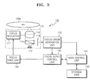
- the optical pickup 110 reads out the data recorded on a recording surface of the optical disk 100a and converts the read data into an electric signal.
- the optical pickup 110 includes a light source 112, a beam splitter 114, an objective lens 116, a focus actuator 117, and a photodetector 118. It is understood that the optical pickup 110 may include other elements that are usable with the optical pickup, such as an aperture controller, or the like, and can have other configurations.
- the light source 112 outputs a laser beam.
- the light source 112 outputs a laser beam having a different wavelength according to the type of the optical disk 100a. For example, when a DVD is loaded as the optical disk 100a, the light source 112 emits a laser beam having a wavelength of about 650 nm.
- the beam splitter 114 reflects or transmits the laser beam emitted by the light source 112 at a predetermined ratio.
- the objective lens 116 focuses the laser beam output from the beam splitter 114 on the recording surface of the optical disk 100a.
- the focus actuator 117 actuates the objective lens 116 up and down (i.e., towards or away from the optical disc 100a) so that the laser beam incident on the optical disk 100a can be accurately focused on the recording surface of the optical disk 100a. That is, the focus actuator 117 actuates the objective lens 116 up and down to turn on a focus servo (not shown) so that the distance between the optical disk 100a and the objective lens 116 is adjusted. Turning on the focus servo signifies that the focus of the optical pickup 110 is pulled in.
- the focus servo is generally used to accurately focus the laser beam on the recording surface of the optical disk 100a to record and/or reproduce data with respect to the optical disk 100a.
- the focus error generation unit 120 generates a focus error signal (FE signal) for the focus servo (i.e., the focus pull-in) using the electric signal output from the photodetector 118.
- the generated focus error signal is provided to the focus servo control unit 130.
- the main control unit 140 controls the overall operation of the focus pull-in control device 100 using various control programs stored in the storage portion 150.
- the main control unit 140 can control the overall operation of the optical recording/reproducing apparatus.
- the main control unit 140 stores the surface vibration information obtained from the previous evaluation of the surface vibration with respect to the disk 100a in the storage portion 150.
- the main control unit 140 controls the focus servo control unit 130 to perform the focus pull-in operation using the surface vibration information that is stored in the storage portion 150 when the next focus is pulled in.
- the focus servo control unit 130 transmits the focus actuator drive signal (FOD) from an initial or a previous disk loading to the main control unit 140.
- FOD focus actuator drive signal
- the operation of the focus pull-in control device 100 that performs the focus pull-in by evaluating the surface vibration and using the surface vibration information is described below.
- the place of the surface vibration evaluation according to aspects of the present invention is not limited to the outer circumference and the evaluation can be performed at any position on the disk. Additionally, the timing of the surface vibration evaluation according to aspects of the present invention is no limited to when a disk is first loaded and it can be performed any time during disk recording and/or reproduction. Also, for a high multiple speed disk system that has a change of speed from a low multiple speed during an initial stage to a high multiple speed during a later stage, the surface vibration evaluation is preferably performed in the initial low multiple speed stage. These multiples are indicated, for example, as 2X, 4X, and so on of a base speed. However, such is not required and the evaluation may be performed at any speed.
- the surface vibration data (or information) is obtained from the outer circumference of the disk 100a using focus actuator drive signals of each disk position corresponding to a sector of the disk 100a obtained by dividing one turn of the spindle by N.
- N may be a number such as a whole number.
- the obtained focus actuator drive signals are then appropriately filtered using a low pass filter.
- the surface vibration data is then stored in the storage portion 150.
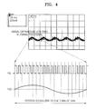
- the focus actuator drive signals may be stored in synchronization with the output from a frequency generator (FG) sensor of the spindle motor, as will be discussed below.
- FG frequency generator
- FIG 4 shows an example of the surface vibration data stored in the storage portion 150.
- the focus actuator drive (FOD) signal equivalent to one turn of a disk is stored in synchronization with the FG signal.
- a sine wave signal that corresponds to the focus actuator drive signal (FOD signal) is subsequently added to the focus actuator drive signal (FOD signal) when the focus pull-in is reattempted.
- the focus pull-in control device 100 searches for the right time to begin focus pull-in using the surface vibration data stored in the storage portion 150. That is, when the focus actuator 117 moves the objective lens 116 up and down at a particular speed, the main control unit 140 controls the focus servo control unit 130 so that the surface vibration data stored in the storage portion 150 that corresponds to the present spindle position is added to the current actuator drive signal. Then, the focus servo control unit 130 controls the focus drive unit 160 to output the combined actuator drive signal after adding in the surface vibration data to the current actuator drive signal.
- Figure 5 is a graph showing a comparison between an FOD signal according to a conventional method and an FOD signal according to an aspect of the present invention.
- the focus actuator drive signal according to the conventional method has a triangular waveform due to the up or down movement of the focus actuator 117 occurring at a particular speed.
- the FOD signal according to an aspect of the present invention is output by adding the surface vibration data FOD of the sine wave shown in Figure 4 to a focus actuator drive signal having a triangular waveform.
- the FOD signal according to an aspect of the present invention has a sine waveform having added surface vibration information as shown in the lower portion of Figure 5.
- the focus actuator 117 is controlled using the previously evaluated surface vibration information instead of simply moving the focus actuator up and down at a particular speed, the focus actuator 117 can be driven taking account of the surface vibration of the disk so that failure of the focus pull-in can be reduced.
- Figure 6 is a flow chart for explaining the focus pull-in operation according to an aspect of the present invention.
- the focus pull-in control device 100 evaluates the surface vibration of the disk (61). The obtained surface vibration information is stored in the storage portion 150 to be used for the next focus pull-in. Next, when the focus pull-in is reattempted, the focus pull-in control device 100 performs the focus pull-in operation again using the stored surface vibration information (62). While not required in all aspects of the present invention, it is understood that elements of the method can be implemented as software readable by a computer or a processor. While described as being obtained through testing, it is understood that the surface vibration information may be prestored, uploaded, hardwired, or the like.
- the focus pull-in can be effectively performed while reducing the failure of the focus pull-in with respect to a disk having a large surface vibration amount.
Landscapes
- Optical Recording Or Reproduction (AREA)
- Moving Of The Head For Recording And Reproducing By Optical Means (AREA)
Applications Claiming Priority (1)
| Application Number | Priority Date | Filing Date | Title |
|---|---|---|---|
| KR1020050097731A KR100717043B1 (ko) | 2005-10-17 | 2005-10-17 | 포커스 인입 제어 장치 및 포커스 인입 제어 방법 |
Publications (2)
| Publication Number | Publication Date |
|---|---|
| EP1777703A2 true EP1777703A2 (de) | 2007-04-25 |
| EP1777703A3 EP1777703A3 (de) | 2007-06-20 |
Family
ID=37680541
Family Applications (1)
| Application Number | Title | Priority Date | Filing Date |
|---|---|---|---|
| EP06122289A Withdrawn EP1777703A3 (de) | 2005-10-17 | 2006-10-13 | Fokussierungssteuervorrichtung und - Verfahren |
Country Status (5)
| Country | Link |
|---|---|
| US (1) | US20070086291A1 (de) |
| EP (1) | EP1777703A3 (de) |
| JP (1) | JP2007115393A (de) |
| KR (1) | KR100717043B1 (de) |
| CN (1) | CN1953069B (de) |
Cited By (1)
| Publication number | Priority date | Publication date | Assignee | Title |
|---|---|---|---|---|
| EP1887571A1 (de) * | 2006-08-08 | 2008-02-13 | Sanyo Electric Co., Ltd. | Fokusservogerät |
Citations (1)
| Publication number | Priority date | Publication date | Assignee | Title |
|---|---|---|---|---|
| US20050162999A1 (en) | 2003-01-20 | 2005-07-28 | Fujitsu Limited | Optical storage system and control method |
Family Cites Families (17)
| Publication number | Priority date | Publication date | Assignee | Title |
|---|---|---|---|---|
| JPS6446240A (en) * | 1987-08-14 | 1989-02-20 | Toshiba Corp | Disk device |
| JPH05234241A (ja) * | 1992-02-20 | 1993-09-10 | Hitachi Ltd | 薄型情報処理装置 |
| JPH0765382A (ja) * | 1993-08-20 | 1995-03-10 | Matsushita Electric Ind Co Ltd | 光ディスク制御装置 |
| JPH09259449A (ja) * | 1996-03-22 | 1997-10-03 | Hitachi Ltd | 光学的情報記録再生装置の位置決め装置 |
| JPH1021571A (ja) * | 1996-07-05 | 1998-01-23 | Hitachi Ltd | ディスク再生装置の学習制御装置 |
| JP2000339712A (ja) * | 1999-06-02 | 2000-12-08 | Ricoh Co Ltd | 光ディスク装置 |
| JP2001236657A (ja) * | 2000-02-21 | 2001-08-31 | Toshiba Corp | 光ディスク読取装置及び光ディスク読取方法 |
| KR20010087634A (ko) * | 2000-03-08 | 2001-09-21 | 구자홍 | 광디스크 구동장치의 포커싱 제어방법 |
| KR100357239B1 (ko) * | 2000-03-13 | 2002-10-25 | 엘지전자 주식회사 | 광디스크 구동장치의 포커싱 제어방법 |
| JP2002222522A (ja) * | 2001-01-24 | 2002-08-09 | Matsushita Electric Ind Co Ltd | 情報ディスク記録再生装置、及び情報ディスク記録再生装置の振動検出方法 |
| JP3517223B2 (ja) * | 2001-04-24 | 2004-04-12 | 株式会社東芝 | 光ディスク装置及び光ディスク処理方法 |
| JP2003022536A (ja) * | 2001-07-03 | 2003-01-24 | Tdk Corp | 光ディスクの再生方法及び光ディスク再生装置 |
| JP2003030876A (ja) * | 2001-07-18 | 2003-01-31 | Toshiba Corp | 光ディスク装置及び光ディスク再生方法 |
| US6912184B2 (en) * | 2001-09-20 | 2005-06-28 | Hitachi-Lg Data Storage Korea, Inc. | Method and apparatus of measuring axial vibration of a disk recording medium |
| TWI220979B (en) * | 2003-04-30 | 2004-09-11 | Liteon It Corp | Method for determining unbalanced disks in CD-ROM |
| KR100555561B1 (ko) * | 2004-03-08 | 2006-03-03 | 삼성전자주식회사 | 광학 디스크 장치의 디스크 면진동에 적응적으로 동작하는고속 포커스 풀-인 제어부 및 포커스 제어 방법 |
| JP2005259248A (ja) * | 2004-03-11 | 2005-09-22 | Funai Electric Co Ltd | 光ディスク記録再生装置 |
-
2005
- 2005-10-17 KR KR1020050097731A patent/KR100717043B1/ko not_active Expired - Fee Related
-
2006
- 2006-09-28 US US11/528,623 patent/US20070086291A1/en not_active Abandoned
- 2006-09-30 CN CN2006101418250A patent/CN1953069B/zh not_active Expired - Fee Related
- 2006-10-13 EP EP06122289A patent/EP1777703A3/de not_active Withdrawn
- 2006-10-16 JP JP2006281571A patent/JP2007115393A/ja active Pending
Patent Citations (1)
| Publication number | Priority date | Publication date | Assignee | Title |
|---|---|---|---|---|
| US20050162999A1 (en) | 2003-01-20 | 2005-07-28 | Fujitsu Limited | Optical storage system and control method |
Cited By (2)
| Publication number | Priority date | Publication date | Assignee | Title |
|---|---|---|---|---|
| EP1887571A1 (de) * | 2006-08-08 | 2008-02-13 | Sanyo Electric Co., Ltd. | Fokusservogerät |
| US7894311B2 (en) | 2006-08-08 | 2011-02-22 | Sanyo Electric Co., Ltd. | Focus servo apparatus |
Also Published As
| Publication number | Publication date |
|---|---|
| EP1777703A3 (de) | 2007-06-20 |
| JP2007115393A (ja) | 2007-05-10 |
| CN1953069A (zh) | 2007-04-25 |
| US20070086291A1 (en) | 2007-04-19 |
| KR20070042003A (ko) | 2007-04-20 |
| CN1953069B (zh) | 2010-09-22 |
| KR100717043B1 (ko) | 2007-05-10 |
Similar Documents
| Publication | Publication Date | Title |
|---|---|---|
| JP2008204607A (ja) | 光ディスク装置およびその駆動方法 | |
| JP4226184B2 (ja) | 情報記録媒体判別装置及び情報記録媒体判別方法 | |
| US7796476B2 (en) | Optical disk device and optical disk gain adjusting method | |
| US7072253B2 (en) | Optical disc reproduction apparatus and automatic adjustment method for same | |
| EP1777703A2 (de) | Fokussierungssteuervorrichtung und - Verfahren | |
| CN1327422C (zh) | 光盘驱动装置及其光学拾取头的倾斜修正方法 | |
| US8014247B2 (en) | Optical disk recording/reproducing apparatus and alternation process method thereof | |
| US20050147001A1 (en) | Method or recording information, computer program, computer readable storage medium, and optical disk apparatus that stably record information on optical disk with high recording quality | |
| JPH1173719A (ja) | 振動検出機能を備えた光ディスク駆動装置、前記光ディスク駆動装置による光ディスクの駆動方法及び光ディスク駆動装置における振動検出方法 | |
| JP4262273B2 (ja) | 光ディスク装置およびデータ読み出し制御方法 | |
| JP2006048824A (ja) | レンズチルト学習制御方法および光ディスク装置 | |
| JP4224503B2 (ja) | 光ディスク装置およびその駆動方法 | |
| US20070147204A1 (en) | Optical disk recording method and optical disk recording and reading apparatus | |
| JP2003030878A (ja) | 光ディスク記録再生装置のウォブル信号検出回路 | |
| JP4252011B2 (ja) | 情報記録再生装置、情報記録再生方法、プログラム及び記憶媒体 | |
| JP4965494B2 (ja) | 記録再生方法および記録再生装置 | |
| JPH09161284A (ja) | フォーカス引き込み方法および光ディスクドライブ装置 | |
| JPH10188457A (ja) | 光ディスク駆動方法及び光ディスク装置 | |
| JPH11120684A (ja) | ディスクドライブ装置、ディスク判別方法 | |
| JP2011108318A (ja) | 光記録媒体、光記録媒体再生装置、及び光記録媒体記録装置 | |
| JP2002216366A (ja) | 光ディスク装置 | |
| JP2002230794A (ja) | 光ディスク装置 | |
| US20060072383A1 (en) | Disc drive apparatus | |
| JP2008004162A (ja) | 光ディスク判別方法および光ディスク再生装置 | |
| JP2007164903A (ja) | 光ディスク装置のフォーカスサーボ復帰処理方法及び光ディスク装置 |
Legal Events
| Date | Code | Title | Description |
|---|---|---|---|
| PUAI | Public reference made under article 153(3) epc to a published international application that has entered the european phase |
Free format text: ORIGINAL CODE: 0009012 |
|
| 17P | Request for examination filed |
Effective date: 20061013 |
|
| AK | Designated contracting states |
Kind code of ref document: A2 Designated state(s): AT BE BG CH CY CZ DE DK EE ES FI FR GB GR HU IE IS IT LI LT LU LV MC NL PL PT RO SE SI SK TR |
|
| AX | Request for extension of the european patent |
Extension state: AL BA HR MK YU |
|
| PUAL | Search report despatched |
Free format text: ORIGINAL CODE: 0009013 |
|
| AK | Designated contracting states |
Kind code of ref document: A3 Designated state(s): AT BE BG CH CY CZ DE DK EE ES FI FR GB GR HU IE IS IT LI LT LU LV MC NL PL PT RO SE SI SK TR |
|
| AX | Request for extension of the european patent |
Extension state: AL BA HR MK YU |
|
| RIC1 | Information provided on ipc code assigned before grant |
Ipc: G11B 7/09 20060101ALI20070516BHEP Ipc: G11B 7/095 20060101ALI20070516BHEP Ipc: G11B 7/085 20060101AFI20070202BHEP |
|
| 17Q | First examination report despatched |
Effective date: 20080124 |
|
| AKX | Designation fees paid |
Designated state(s): DE FR GB IT NL |
|
| STAA | Information on the status of an ep patent application or granted ep patent |
Free format text: STATUS: THE APPLICATION IS DEEMED TO BE WITHDRAWN |
|
| 18D | Application deemed to be withdrawn |
Effective date: 20120111 |