EP1777906A1 - Appareil de compensation d erreur d amplitude et appareil de compensation d erreur d orthogonalité - Google Patents
Appareil de compensation d erreur d amplitude et appareil de compensation d erreur d orthogonalité Download PDFInfo
- Publication number
- EP1777906A1 EP1777906A1 EP06756819A EP06756819A EP1777906A1 EP 1777906 A1 EP1777906 A1 EP 1777906A1 EP 06756819 A EP06756819 A EP 06756819A EP 06756819 A EP06756819 A EP 06756819A EP 1777906 A1 EP1777906 A1 EP 1777906A1
- Authority
- EP
- European Patent Office
- Prior art keywords
- quadrature
- amplitude
- section
- error
- power
- Prior art date
- Legal status (The legal status is an assumption and is not a legal conclusion. Google has not performed a legal analysis and makes no representation as to the accuracy of the status listed.)
- Withdrawn
Links
Images






Classifications
-
- H—ELECTRICITY
- H04—ELECTRIC COMMUNICATION TECHNIQUE
- H04L—TRANSMISSION OF DIGITAL INFORMATION, e.g. TELEGRAPHIC COMMUNICATION
- H04L27/00—Modulated-carrier systems
- H04L27/32—Carrier systems characterised by combinations of two or more of the types covered by groups H04L27/02, H04L27/10, H04L27/18 or H04L27/26
- H04L27/34—Amplitude- and phase-modulated carrier systems, e.g. quadrature-amplitude modulated carrier systems
- H04L27/38—Demodulator circuits; Receiver circuits
- H04L27/3845—Demodulator circuits; Receiver circuits using non - coherent demodulation, i.e. not using a phase synchronous carrier
- H04L27/3854—Demodulator circuits; Receiver circuits using non - coherent demodulation, i.e. not using a phase synchronous carrier using a non - coherent carrier, including systems with baseband correction for phase or frequency offset
- H04L27/3863—Compensation for quadrature error in the received signal
Definitions
- the present invention relates to a demodulation device for use in digital radio communication. More particularly, the present invention relates to a device for detecting and correcting an amplitude error or a quadrature skew error between an in-phase component and a quadrature component of a complex signal obtained by quadrature demodulation in an analog quadrature demodulation section.
- Digital modulation schemes for use in digital radio communication include digital phase modulation schemes (e.g., BPSK (Binary Phase Shift Keying), QPSK (Quadrature Phase Shift Keying), 8PSK (Phase Shift Keying)), QAM (Quadrature Amplitude Modulation), and the like.
- digital phase modulation schemes e.g., BPSK (Binary Phase Shift Keying), QPSK (Quadrature Phase Shift Keying), 8PSK (Phase Shift Keying)), QAM (Quadrature Amplitude Modulation), and the like.
- BPSK Binary Phase Shift Keying
- QPSK Quadratture Phase Shift Keying
- 8PSK Phase Shift Keying
- QAM Quadrature Amplitude Modulation
- an in-phase component and a quadrature component of the IQ signal output from the analog quadrature demodulation section are orthogonal to each other, and have the same average amplitude.
- the analog quadrature demodulation section is affected by characteristic variations, temperature characteristics, voltage characteristics, and the like of the analog element, so that an amplitude error or a quadrature skew error occurs between the in-phase component and the quadrature component of the IQ signal. Therefore, when the IQ signal output from the analog quadrature demodulation section is directly subjected to detection, a bit error rate (hereinafter referred to as BER) increases.
- BER bit error rate
- Patent Document 1 described below discloses a demodulation circuit which determines quadrants on an IQ plane of the IQ signal, stores amplitude values of the IQ signal, depending on the quadrants in which the IQ signal is present, and corrects a quadrature skew error using a difference between the stored amplitude values as quadrature error information.
- Patent Document 2 described below discloses an amplitude control circuit which corrects amplitudes of one of an in-phase component and a quadrature component of an input IQ signal using a value obtained by integration of a difference in amplitude value between the in-phase component and the quadrature component using a loop filter.
- Patent Document 3 discloses a circuit which calculates a coefficient which is adaptively updated by applying the CMA (Constant Modulus Algorithm) to an output of the analog quadrature demodulation section, and corrects and outputs an amplitude error and a quadrature skew error.
- CMA Constant Modulus Algorithm
- the amplitude control circuit described in Patent Document 2 may erroneously detect an amplitude error between an in-phase component and a quadrature component in the case of FIG. 6 or when there is not an amplitude error between the two components. Also, since an amplitude of one of an in-phase component and a quadrature component is corrected, a difference may occur between the power of a signal before correction and the power of the signal after correction, resulting in an increase in BER.
- the amplitude error and quadrature skew error correcting circuit described in Patent Document 3 cannot perform amplitude error correction and quadrature skew error correction separately, so that an interaction between amplitude error correction and quadrature skew error correction hinders high-accuracy correction. Also, a number of multipliers are required, resulting in an increase in circuit area.
- An object of the present invention is to provide an amplitude error compensating device and a quadrature skew error compensating device which can correctly and stably correct an amplitude error and a quadrature skew error even when the distribution of signal points of an input complex signal is not uniform.
- the present invention comprises an amplitude correcting section for performing amplitude correction with respect to an in-phase component and a quadrature component of a complex signal obtained by quadrature demodulation, based on amplitude error information, and outputting a resultant amplitude-corrected complex signal, and an amplitude error detecting section for obtaining the amplitude error information, depending on amplitudes of an in-phase component and a quadrature component of the amplitude-corrected complex signal, thereby reducing a difference between the amplitudes of the in-phase component and the quadrature component of the amplitude-corrected complex signal.
- the present invention comprises a quadrature skew correcting section for performing quadrature skew correction with respect to a complex signal obtained by quadrature demodulation, based on quadrature skew error information, and outputting a resultant quadrature skew-corrected complex signal, and a quadrature skew error detecting section for obtaining a quadrature skew error between an in-phase component and a quadrature component of the quadrature skew-corrected complex signal, and outputting the quadrature skew error as the quadrature skew error information, thereby decreasing a quadrature skew between the in-phase component and the quadrature component of the quadrature skew-corrected complex signal.
- the present invention provides an amplitude error compensating device comprising an amplitude correcting section for performing amplitude correction with respect to an in-phase component and a quadrature component of a complex signal obtained by quadrature demodulation, based on amplitude error information, and outputting a resultant amplitude-corrected complex signal, and an amplitude error detecting section for obtaining the amplitude error information, depending on amplitudes of an in-phase component and a quadrature component of the amplitude-corrected complex signal.
- the amplitude error detecting section comprises a power difference calculating section for obtaining as a power error a difference in power between the in-phase component and the quadrature component of the amplitude-corrected complex signal, a rotation detecting section for detecting a rotation of a signal point of the amplitude-corrected complex signal, and outputting the result as a rotation detect signal, an error information control section for outputting the power error when the rotation detect signal indicates that a rotation of the signal point has been detected, and 0 when the rotation detect signal indicates that a rotation of the signal point has not been detected, and a smoothing section for smoothing an output of the error information control section, and outputting the result as the amplitude error information.
- the amplitude correcting section performs the amplitude correction so that a power of the complex signal obtained by quadrature demodulation and a power of the amplitude-corrected complex signal are equal to each other.
- the amplitude correcting section performs the amplitude correction by multiplying one of the in-phase component and the quadrature component of the complex signal obtained by quadrature demodulation by the amplitude error information, and the other by a value obtained by converting the amplitude error information in accordance with a predetermined relationship.
- the present invention also provides an amplitude error compensating device comprising an amplitude correcting section for performing amplitude correction with respect to an in-phase component and a quadrature component of a complex signal obtained by quadrature demodulation, based on amplitude error information, and outputting a resultant amplitude-corrected complex signal, and an amplitude error detecting section for obtaining the amplitude error information, depending on amplitudes of an in-phase component and a quadrature component of the amplitude-corrected complex signal.
- the amplitude error detecting section comprises a first power calculating section for obtaining a power of the amplitude-corrected complex signal, a second power calculating section for obtaining a power of the complex signal obtained by quadrature demodulation, an averaging section for obtaining an average value of the power obtained by the second power calculating section, and outputting the average value as an average power, a subtractor for obtaining a difference between the power obtained by the first power calculating section and the average power, and outputting the difference as a power difference, an area determining section for determining to which of a plurality of areas on an IQ plane a signal point of the amplitude-corrected complex signal belongs, and outputting the result as an area determination signal, a sign determining section for outputting the power difference or the power difference whose sign has been inverted, in accordance with the area determination signal, and a smoothing section for smoothing an output of the sign determining section, and outputting the result as the amplitude error information.
- the amplitude error information can be correctly detected, thereby making it possible to perform amplitude error correction without a malfunction, even when the distribution of signal points of an input complex signal is not uniform.
- the area determining section determines which of absolute values of the in-phase component and the quadrature component of the amplitude-corrected complex signal is larger than the other, and outputting the result as the area determination signal.
- the present invention also provides a quadrature skew error compensating device comprising a quadrature skew correcting section for performing quadrature skew correction with respect to a complex signal obtained by quadrature demodulation, based on quadrature skew error information, and outputting a resultant quadrature skew-corrected complex signal, and a quadrature skew error detecting section for obtaining a quadrature skew error between an in-phase component and a quadrature component of the quadrature skew-corrected complex signal, and outputting the quadrature skew error as the quadrature skew error information.
- the quadrature skew error detecting section comprises a power calculating section for obtaining a power of the quadrature skew-corrected complex signal, a quadrant determining section for determining to which of quadrants on an IQ plane a signal point of the quadrature skew-corrected complex signal belongs, and outputting the result as a quadrant determination signal, a sign determining section for outputting a value of the power or the power whose sign has been inverted, as a power error, in accordance with the quadrant determination signal, a rotation detecting section for detecting a rotation of the signal point of the quadrature skew-corrected complex signal, and outputting the result as a rotation detect signal, an error information control section for outputting the power error when the rotation detect signal indicates that the rotation of the signal point has been detected, and 0 when the rotation detect signal indicates that the rotation of the signal point has not been detected, and a smoothing section for smoothing an output of the error information control section, and outputting the result as the quadrat
- the present invention also provides a quadrature skew error compensating device comprising a quadrature skew correcting section for performing quadrature skew correction with respect to a complex signal obtained by quadrature demodulation, based on quadrature skew error information, and outputting a resultant quadrature skew-corrected complex signal, and a quadrature skew error detecting section for obtaining a quadrature skew error between an in-phase component and a quadrature component of the quadrature skew-corrected complex signal, and outputting the quadrature skew error as the quadrature skew error information.
- the quadrature skew error detecting section comprises a multiplier for multiplying the in-phase component and the quadrature component of the quadrature skew-corrected complex signal, and outputting the result, and a smoothing section for smoothing the result of the multiplication by the multiplier, and outputting the result as the quadrature skew error information.
- the quadrature skew error compensating device preferably further comprises a frequency offset detector for detecting a frequency offset of the quadrature skew-corrected complex signal, and an error information control section for outputting the result of the multiplication by the multiplier to the smoothing section in accordance with the result of the detection by the frequency offset detector.
- the present invention also provides a quadrature skew error compensating device comprising a quadrature skew correcting section for performing quadrature skew correction with respect to a complex signal obtained by quadrature demodulation, based on quadrature skew error information, and outputting a resultant quadrature skew-corrected complex signal, and a quadrature skew error detecting section for obtaining a quadrature skew error between an in-phase component and a quadrature component of the quadrature skew-corrected complex signal, and outputting the quadrature skew error as the quadrature skew error information.
- the quadrature skew error detecting section comprises a first power calculating section for obtaining a power of the quadrature skew-corrected complex signal, a second power calculating section for obtaining a power of the complex signal obtained by the quadrature demodulation, an averaging section for obtaining an average value of the power obtained in the second power calculating section, and outputting the average value as an average power, a subtractor for obtaining a difference between the power calculated by the first power calculating section and the average power, and outputting the difference as a power difference, a quadrant determining section for determining to which of quadrants on an IQ plane a signal point of the quadrature skew-corrected complex signal belongs, and outputting the result as a quadrant determination signal, a sign determining section for outputting a value of the power difference or the power difference whose sign has been inverted, as a power error, in accordance with the quadrant determination signal, and a smoothing section for smoothing an output of the sign determining section,
- quadrature skew error information can be correctly detected, thereby making it possible to perform quadrature skew error correction without a malfunction, even when the distribution of signal points of an input complex signal is not uniform.
- the present invention also provides an amplitude/quadrature skew error compensating device comprising an amplitude correcting section for performing amplitude correction with respect to an in-phase component and a quadrature component of a complex signal obtained by quadrature demodulation, based on amplitude error information, and outputting a resultant amplitude-corrected complex signal, an amplitude error detecting section for obtaining the amplitude error information, depending on amplitudes of an in-phase component and a quadrature component of the amplitude-corrected complex signal, a quadrature skew correcting section for performing quadrature skew correction with respect to the amplitude-corrected complex signal, based on quadrature skew error information, and outputting a resultant quadrature skew-corrected complex signal, and a quadrature skew error detecting section for obtaining a quadrature skew error between an in-phase component and a quadrature component of the quadrature skew-correcte
- amplitude/quadrature skew error compensating device which correctly performs amplitude/quadrature skew error correction without a malfunction. It is also possible to perform amplitude/quadrature skew error correction without occurrence of an error in signal power between before and after correction.
- FIG. 1 is a block diagram of a demodulation device according to a first embodiment of the present invention.
- the demodulation device of FIG. 1 comprises an analog section 2 and a digital section 4.
- the analog section 2 comprises an amplification section 11 and an analog quadrature demodulation section 12.
- the digital section 4 comprises an amplitude/quadrature skew error compensating section 15, a detection section 16, and a discrimination section 17.
- the amplification section 11 amplifies digital modulated waves received by an antenna 1, and outputs the amplified waves to the analog quadrature demodulation section 12.
- the analog quadrature demodulation section 12 subjects a signal output from the amplification section 11 to quadrature demodulation, and outputs a resultant signal to the amplitude/quadrature skew error compensating section 15.
- the quadrature-demodulated signal is a complex signal, which has an in-phase component (in-phase signal) I and a quadrature component (quadrature signal) Q.
- the complex signal is referred to as an IQ signal.
- the analog quadrature demodulation section 12 has a sine wave generator 21, a ⁇ /2 phase shifter 22, multipliers 23 and 24, low-pass filters 25 and 26, and AD (Analog to Digital) converters 27 and 28.
- the sine wave generator 21 generates and outputs a sine wave to the ⁇ /2 phase shifters 22 and the multiplier 23.
- the ⁇ /2 phase shifter 22 shifts the phase of the output of the sine wave generator 21 by ⁇ /2 and outputs the result to the multiplier 24.
- the multiplier 23 multiplies the output of the amplification section 11 by the output of the sine wave generator 21 and outputs the result to the low-pass filter 25.
- the multiplier 24 multiplies the output of the amplification section 11 by the output of the ⁇ /2 phase shifter 22 and outputs the result to the low-pass filter 26.
- the low-pass filters 25 and 26 eliminate high frequency components of respective input signals, and output the results to the AD converters 27 and 28, respectively.
- the AD converters 27 and 28 convert the respective input signals into digital signals, and output the obtained signals as an in-phase component I and a quadrature component Q to the amplitude/quadrature skew error compensating section 15.
- the amplitude/quadrature skew error compensating section 15 subjects the in-phase component I and the quadrature component Q output from the AD converters 27 and 28 of the analog quadrature demodulation section 12 to amplitude error correction and quadrature skew error correction, and outputs the result to the detection section 16.
- the detection section 16 detects the in-phase component I and the quadrature component Q corrected by the amplitude/quadrature skew error compensating section 15, and outputs the result to the discrimination section 17.
- the discrimination section 17 discriminates signal points on the IQ plane with respect to the output of the detection section 16, and outputs a resultant digital demodulated signal.
- FIGS. 2(a), 2(b) and 2(c) are diagrams schematically illustrating exemplary average amplitudes of the IQ signal output from the analog quadrature demodulation section 12 as a locus on the IQ plane.
- FIG. 2(a) indicates an ideal case.
- FIG. 2(b) indicates the case where there is an amplitude error between the in-phase component I and the quadrature component Q.
- FIG. 2(c) indicates the case where there is a quadrature skew error between the in-phase component I and the quadrature component Q.
- the analog quadrature demodulation section 12 is affected by characteristics variations, temperature characteristics, voltage characteristics, and the like of the analog element included therein, so that an amplitude error and a quadrature skew error occur between the in-phase component I and the quadrature component Q output therefrom. Therefore, the amplitude/quadrature skew error compensating section 15 corrects an IQ signal whose average amplitudes are as illustrated in FIGS. 2(b) and 2(c) into an IQ signal whose average amplitudes are as illustrated in FIG. 2(a), or in other words, corrects a distribution of signal points (values of the in-phase component I and the quadrature component Q are represented by an I-axis coordinate and a Q-axis coordinate, respectively), thereby suppressing BER.
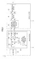
- FIG. 3 is a block diagram illustrating an exemplary configuration of the amplitude/quadrature skew error compensating section 15 of FIG. 1.
- the amplitude/quadrature skew error compensating section 15 has an amplitude error detecting section 30, an amplitude correcting section 40, a quadrature skew error detecting section 50, and a quadrature skew correcting section 60.
- the amplitude/quadrature skew error compensating section 15 initially subjects an input IQ signal to amplitude error correction, and then subjects the amplitude error-corrected IQ signal to quadrature skew error correction. In other words, amplitude correction and quadrature skew correction are separately performed.
- the amplitude correcting section 40 subjects the in-phase component I and the quadrature component Q output from the analog quadrature demodulation section 12 to amplitude error correction based on an in-phase amplitude error magnification factor ⁇ as amplitude error information output from the amplitude error detecting section 30 so that a difference in amplitude between the in-phase component I and the quadrature component Q is reduced, and outputs an amplitude-corrected in-phase component I' and quadrature component Q'.
- the amplitude error detecting section 30 calculates an in-phase amplitude error magnification factor ⁇ for the in-phase component I' and the quadrature component Q', and outputs the in-phase amplitude error magnification factor ⁇ to the amplitude correcting section 40.
- the amplitude error detecting section 30 and the amplitude correcting section 40 perform feedback correction with respect to amplitude errors.
- the quadrature skew correcting section 60 subjects the in-phase component I' and the quadrature component Q' to quadrature skew error correction based on quadrature skew error information ⁇ output from the quadrature skew error detecting section 50, and outputs a quadrature skew-corrected in-phase component I" and quadrature component Q".
- the quadrature skew error detecting section 50 obtains quadrature skew error information ⁇ for the in-phase component I" and the quadrature component Q", and outputs the quadrature skew error information ⁇ to the quadrature skew correcting section 60.
- the quadrature skew error detecting section 50 and the quadrature skew correcting section 60 perform feedback correction with respect to quadrature skew errors.
- FIG. 4 is a block diagram illustrating an exemplary configuration of the amplitude error detecting section 30 of FIG. 3.
- the amplitude error detecting section 30 comprises a power difference calculating section 31, a rotation detecting section 33, an error information control section 34, and a low-pass filter (hereinafter referred to as an LPF) 35 as a smoothing section.
- an LPF low-pass filter
- the power difference calculating section 31 has multipliers 131A and 131B, and a subtractor 131C.
- the multiplier 131A squares the in-phase component I' to obtain a power thereof, and outputs the power to the subtractor 131C.
- the multiplier 131B squares the quadrature component Q' to obtain a power thereof, and outputs the power to the subtractor 131C.
- the subtractor 131C calculates a difference between the power of the in-phase component I' and the power of the quadrature component Q' (here, the power of the in-phase component I' is subtracted from the power of the quadrature component Q'), and outputs the difference as an IQ power error DG to the error information control section 34.
- the rotation detecting section 33 comprises exclusive OR (XOR) operators 133A and 133C, and a D flip-flop 133B.
- the XOR operator 133A obtains an exclusive OR (quadrant determination signal) of a sign bit (I'msb) of the in-phase component I' and a sign bit (Q'rnsb) of the quadrature component Q', and outputs the quadrant determination signal to the D flip-flop 133B and the XOR operator 133C.
- the XOR operator 133A outputs "0" as the quadrant determination signal when a current signal point of the IQ signal is present in the first or third quadrant on the IQ plane, and "1" when the signal point is present in the second or fourth quadrant.
- the D flip-flop 133B delays the quadrant determination signal by, for example, one clock and outputs the result to the XOR operator 133C.
- the XOR operator 133C obtains the exclusive OR of the quadrant determination signal and the quadrant determination signal delayed in the D flip-flop 133B, and outputs the result as a rotation detect signal RG to the error information control section 34.
- the rotation detecting section 33 does not detect a rotation of a signal point of the IQ signal and sets the rotation detect signal RG to be "0" when there is not a change in the quadrant determination signal, and detects a rotation of a signal point of the IQ signal and sets the rotation detect signal RG to be "1" when there is a change in the quadrant determination signal.
- the error information control section 34 outputs "0" when the rotation detect signal RG is "0", and the IQ power error DG when the rotation detect signal RG is "1", as IQ power error information DG2 to the LPF 35.
- the LPF 35 has a gain adjuster 135A, an adder 135B, and a D flip-flop 135C, and is configured as a loop filter.
- the gain adjuster 135A adjusts a gain of the IQ power error information DG2 and outputs the result to the adder 135B.
- the adder 135B and the D flip-flop 135C accumulate outputs of the gain adjuster 135A, and output the result as the in-phase amplitude error magnification factor ⁇ .
- FIG. 5 is a schematic diagram illustrating a distribution of signal points on an IQ plane of an IQ signal obtained by quadrature demodulation when the IQ signal has a frequency offset with respect to carrier waves, during reception of a BPSK-modulated signal.
- the signal points of the IQ signal transition in the following manner: A ⁇ B ⁇ C ⁇ D ⁇ E ⁇ F ⁇ G.
- the rotation detecting section 33 does not detect a rotation of a signal point of an input IQ signal, when the signal point of the IQ signal transitions in the second and fourth quadrants (A ⁇ B ⁇ C), and when the signal point of the IQ signal transitions in the first and third quadrants (D ⁇ E ⁇ F).
- the error information control section 34 does not output the IQ power error DG, and outputs 0 to the LPF 35.
- the rotation detecting section 33 detects a rotation of a signal point of an IQ signal when the signal point transitions between the second and fourth quadrants and the first and third quadrants (C ⁇ D and F ⁇ G).
- the error information control section 34 outputs the IQ power error DG to the LPF 35.
- the amplitude error detecting section 30 performs amplitude error calculation between the in-phase component I' and the quadrature component Q'.
- FIG. 6 is a schematic diagram illustrating a distribution of signal points on an IQ plane of an IQ signal obtained by quadrature demodulation when the IQ signal does not have a frequency offset with respect to carrier waves, during reception of a BPSK-modulated signal.
- the signal point on the IQ plane of the IQ signal transitions only in the second and fourth quadrants (or the first and third quadrants).
- the rotation detecting section 33 does not detect a rotation of the signal point, even when the signal point of the IQ signal transitions.
- the error information control section 34 outputs 0 to the LPF 35.
- the amplitude error detecting section 30 does not perform amplitude error calculation between the in-phase component I' and the quadrature component Q'.
- the amplitude error detecting section 30 detects a rotation of a signal point (an IQ vector) of an IQ signal, and only when a rotation has been detected, performs amplitude error calculation between the in-phase component I' and the quadrature component Q'.
- the distribution of signal points of an IQ signal is not uniform as illustrated in FIG. 6 (e.g., a quadrature-demodulated IQ signal has a frequency offset of 0), it is possible to avoid erroneous detection of an amplitude error.
- a block for determining whether or not an IQ signal is a BPSK-modulated signal may be provided, and based on the result of the determination, the error information control section 34 may control the IQ power error information DG2. Also, since the detection section 16 typically determines whether or not an IQ signal is a BPSK-modulated signal, the result of the determination may be used.
- FIG. 7 is a block diagram illustrating an exemplary configuration of the amplitude correcting section 40 of FIG. 3.
- the amplitude correcting section 40 has multipliers 41 and 42, and a quadrature amplitude error magnification factor calculating section 43.
- the quadrature amplitude error magnification factor calculating section 43 calculates a quadrature amplitude error magnification factor ⁇ based on the in-phase amplitude error magnification factor ⁇ output from the amplitude error detecting section 30.
- the multiplier 41 multiplies the in-phase component I by the in-phase amplitude error magnification factor ⁇ , and outputs the result as the in-phase component I'.
- the multiplier 42 multiplies the quadrature component Q by the quadrature amplitude error magnification factor ⁇ , and outputs the result as the quadrature component Q'.
- the quadrature amplitude error magnification factor calculating section 43 calculates the quadrature amplitude error magnification factor ⁇ so that the powers of the in-phase component I and the quadrature component Q input to the amplitude correcting section 40 are equal to the powers of the in-phase component I' and the quadrature component Q' output from the amplitude correcting section 40.
- FIG. 8 is a diagram schematically illustrating average amplitudes of an IQ signal as a locus on an IQ plane when there is an amplitude error between an in-phase component and a quadrature component. A method of calculating the quadrature amplitude error magnification factor ⁇ will be described in detail.
- average amplitudes of an IQ signal having these as components thereof are represented by an ellipse SG of FIG. 8.
- average amplitudes of an IQ signal having these as components thereof are represented by a perfect circle S of FIG. 8.
- the major radius and the minor radius of the ellipse SG are represented by A and B, respectively, and the radius of the perfect circle S is represented by R.
- I In-phase component
- Q Quadrature component
- the quadrature amplitude error magnification factor calculating section 43 calculates the quadrature amplitude error magnification factor ⁇ from the in-phase amplitude error magnification factor ⁇ using the relationship of equation (6).
- the quadrature amplitude error magnification factor calculating section 43 can be implemented as, for example, a ROM (read-only memory) storing a look-up table representing the relationship of equation (6).
- the amplitude correcting section 40 adjusts the gains of the in-phase component I and the quadrature component Q under the condition that the average powers before and after correction are the same and based on the in-phase amplitude error magnification factor ⁇ , which is a scalar.
- the quadrature amplitude error magnification factor ⁇ is obtained from the in-phase amplitude error magnification factor ⁇
- the quadrature amplitude error magnification factor ⁇ may be obtained in the amplitude error detecting section, and then the in-phase amplitude error magnification factor ⁇ may be obtained using equation (6).
- FIG. 9 is a block diagram illustrating an exemplary configuration of the quadrature skew error detecting section 50 of FIG. 3.
- the quadrature skew error detecting section 50 comprises a power calculating section 51, a sign determining section 52, a rotation detecting section 53, an error information control section 54, an LPF 55 as a smoothing section, and a quadrant determining section 56.
- the power calculating section 51 has multipliers 151A and 151B, and an adder 151C.
- the multiplier 151A squares the in-phase component I" to obtain a power thereof, and outputs the power to the adder 151C.
- the multiplier 151B squares the quadrature component Q" to obtain a power thereof, and outputs the power to the adder 151C.
- the adder 151C calculates the sum of the power of the in-phase component I" and the power of the quadrature component Q", and outputs a resultant value as a power P to the sign determining section 52.
- the sign determining section 52 has a sign inverter 152A and a selector 152B.
- the sign inverter 152A inverts the sign of the power P and outputs the result to the selector 152B.
- the selector 152B selects the power P when the quadrant determination signal output from the quadrant determining section 56 is "0", and the power P whose sign has been inverted by the sign inverter 152A when the quadrant determination signal is "1", and outputs the selected value as a quadrant power error DP to the error information control section 54.
- the quadrant determining section 56 obtains the exclusive OR of a sign bit (I"msb) of the in-phase component I" and a sign bit (Q"msb) of the quadrature component Q", which are output from the quadrature skew correcting section 60, and outputs the result as a quadrant determination signal to the selector 152B.
- the quadrant determination signal is "0" when a signal point represented by the in-phase component I" and the quadrature component Q" is present in the first or third quadrant on an IQ plane, and "1" when the signal point is present in the second or fourth quadrant.
- the rotation detecting section 53 has the same configuration as that of the rotation detecting section 33 of FIG. 4, and obtains a rotation detect signal RP based on the sign bit (I"msb) of the in-phase component I" and the sign bit (Q"msb) of the quadrature component Q" and outputs the result to the error information control section 54.
- the error information control section 54 outputs "0" when the rotation detect signal RP is "0", and the quadrant power error DP when the rotation detect signal RP is "1", as quadrant power error information DP2 to the LPF 55.
- the LPF 55 has the same configuration as that of the LPF 35 of FIG. 4, and accumulates the quadrant power error information DP2 after gain adjustment, and outputs resultant quadrature skew error information ⁇ .
- the rotation detecting section 53 detects a rotation of signal points of an IQ signal when the signal points transition between the second and fourth quadrants and the first and third quadrants (C ⁇ D and F ⁇ G).
- the error information control section 54 outputs the quadrant power error DP.
- the quadrature skew error detecting section 50 performs quadrature skew error calculation between the in-phase component I" and the quadrature component Q".
- the quadrature skew error detecting section 50 detects a rotation of signal points (IQ vectors) of an IQ signal, and only when a rotation has been detected, performs quadrature skew error calculation between the in-phase component I" and the quadrature component Q".
- the quadrature skew error detecting section 50 detects a rotation of signal points (IQ vectors) of an IQ signal, and only when a rotation has been detected, performs quadrature skew error calculation between the in-phase component I" and the quadrature component Q".
- a block for determining whether or not an IQ signal is a BPSK-modulated signal may be provided, and based on the result of the determination, the error information control section 54 may control the quadrant power error information DP2. Also, since the detection section 16 typically determines whether or not an IQ signal is a BPSK-modulated signal, the result of the determination may be used.
- FIG. 10 is a block diagram illustrating an exemplary configuration of the quadrature skew correcting section 60 of FIG. 3.
- the quadrature skew correcting section 60 comprises a conversion ROM 61, multipliers 62 and 63, and an adder 64.
- the quadrature skew correcting section 60 handles the quadrature skew error information ⁇ (deviation of quadrature skew) output from the quadrature skew error detecting section 50, as tan ⁇ , since ⁇ is sufficiently small.
- the conversion ROM 61 converts the quadrature skew error information tan ⁇ into 1/cos ⁇ , which is in turn output.
- the multiplier 63 multiplies 1/cos ⁇ output from the conversion ROM 61 by the quadrature component Q', and outputs the result of the multiplication to the adder 64.
- the multiplier 62 multiplies the in-phase component I' by the quadrature skew error information tan ⁇ , and outputs the result of the multiplication to the adder 64.
- the adder 64 adds the results of the multiplication obtained in the multipliers 62 and 63, and outputs the corrected quadrature component Q".
- the quadrature skew correcting section 60 Since the preceding amplitude correcting section 40 has performed amplitude correction with respect to the in-phase component I and the quadrature component Q, the in-phase component I' and the quadrature component Q' after amplitude correction have the same amplitude.
- the quadrature component Q" after quadrature skew error correction is represented by:
- the quadrature skew correcting section 60 receives the in-phase component I' and the quadrature component Q' and performs the calculation of equation (9), thereby making it possible to correct the quadrature skew error information ⁇ of the quadrature component Q', and output the corrected quadrature component Q".
- the amplitude/quadrature skew error compensating section of FIG. 3 for example, during reception of a BPSK-modulated signal, even when an IQ signal obtained by quadrature demodulation does not have a frequency offset with respect to carrier waves, amplitude/quadrature skew error correction can be correctly performed without a malfunction.
- the amplitude/quadrature skew error compensating section can be implemented as a circuit having a small area, and amplitude/quadrature skew error correction can be performed without a change in signal power between before and after correction.
- FIG. 11 is a block diagram illustrating an exemplary configuration of an amplitude/quadrature skew error compensating section 215 according to a second embodiment of the present invention.
- the amplitude/quadrature skew error compensating section 215 is used in place of the amplitude/quadrature skew error compensating section 15 in the demodulation device of FIG. 1 .
- the amplitude/quadrature skew error compensating section 215 of FIG. 11 comprises a quadrature skew error detecting section 250 in place of the quadrature skew error detecting section 50, and further comprises a frequency offset detector 70, in the amplitude/quadrature skew error compensating section 15 of FIG. 3.
- the other parts are the same as those which have been described in the first embodiment, and are indicated by the same reference numerals and will not be described.
- the frequency offset detector 70 detects a frequency offset with respect to carrier waves from an IQ signal output from the quadrature skew correcting section 60, and outputs "1" when the value of the detected frequency offset is larger than a previously set threshold value ⁇ , and "0" when the value is smaller than the threshold value ⁇ , as a control signal F to the quadrature skew error detecting section 250.
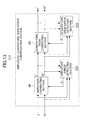
- FIG. 12 is a block diagram illustrating an exemplary configuration of the quadrature skew error detecting section 250 of FIG. 11.
- the quadrature skew error detecting section 250 has a multiplier 251, an error information control section 254, and an LPF 255.
- the multiplier 251 multiplies the in-phase component I" and the quadrature component Q" of an IQ signal output from the quadrature skew correcting section 60, and outputs the result of the multiplication to the error information control section 254.
- the error information control section 254 outputs 0 when the control signal F output from the frequency offset detector 70 is "0", and the result of the multiplication in the multiplier 251 when the control signal F is "1", to the LPF 255.
- the LPF 255 has the same configuration as that of the LPF 35 of FIG. 4, and accumulates the output of the error information control section 254 after gain adjustment, and outputs a resultant quadrature skew error information ⁇ .
- the first term of equation (13) is 0, and only the second term (quadrature skew error component) can be detected.
- the quadrature skew error detecting section 250 can obtain the quadrature skew error information ⁇ by calculating an integral of the result of multiplication of the in-phase component I" by the quadrature component Q" using the LPF 255.
- a simple circuit can be used to perform quadrature skew error detection while suppressing the circuit scale.
- the output of the multiplier 251 may be directly input to the LPF 255 without using the error information control section 254, so as to perform quadrature skew error detection.
- a block for determining whether or not an IQ signal is a BPSK-modulated signal may be provided, and based on the result of the determination, the error information control section 254 may be controlled. Also, since the detection section 16 typically determines whether or not an IQ signal is a BPSK-modulated signal, the result of the determination may be used.
- FIG. 13 is a block diagram illustrating an exemplary configuration of an amplitude/quadrature skew error compensating section 315 according to a third embodiment of the present invention.
- the amplitude/quadrature skew error compensating section 315 is used in place of the amplitude/quadrature skew error compensating section 15 in the demodulation device of FIG. 1.
- the amplitude/quadrature skew error compensating section 315 of FIG. 13 comprises an amplitude error detecting section 330 and a quadrature skew error detecting section 350 in place of the amplitude error detecting section 30 and the quadrature skew error detecting section 50, respectively, in the amplitude/quadrature skew error compensating section 15 of FIG. 3.
- the other parts are the same as those which have been described in the first embodiment, and are indicated by the same reference numerals and will not be described.
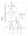
- FIG. 14 is a block diagram illustrating an exemplary configuration of the quadrature skew error detecting section 350 of FIG. 13.
- the quadrature skew error detecting section 350 comprises power calculating sections 351 and 359, a sign determining section 352, an LPF 355, a quadrant determining section 356, an averager 357, and a subtractor 358.
- the power calculating sections 351 and 359 have the same configuration as that of the power calculating section 51 of FIG. 9.
- the power calculating section 359 obtains and adds power values of the in-phase component I' and the quadrature component Q', and outputs the result as a power value PA to the averager 357 .
- the averager 357 averages the power value PA, and outputs a resultant average power PV to the subtractor 358.
- the power calculating section 351 obtains and adds power values of the in-phase component I" and the quadrature component Q", and outputs the result as a power value PB to the subtractor 358.
- the subtractor 358 subtracts the power value PB from the average power PV, and outputs the result as a power difference PD to the sign determining section 352.
- the quadrant determining section 356 obtains the exclusive OR of a sign bit of the in-phase component I" and a sign bit of the quadrature component Q", and outputs the result as a quadrant determination signal to the sign determining section 352.
- the sign determining section 352 has substantially the same configuration as that of the sign determining section 52 of FIG. 9.
- the sign determining section 352 selects the power difference PD when the quadrant determination signal output from the quadrant determining section 356 is "1", and the power difference PD whose sign has been inverted when the quadrant determination signal is "0”, and outputs the selected value to the LPF 355.
- the LPF 355 has the same configuration as that of LPF 35 of FIG. 4, and accumulates the output of the sign determining section 352 after gain adjustment, and outputs a resultant quadrature skew error information ⁇ .
- FIG. 15 is a diagram schematically illustrating exemplary average amplitudes of an IQ signal as a locus on an IQ plane when there is a quadrature skew error between an in-phase component and a quadrature component.
- a phase difference between the in-phase component I" and the quadrature component Q" is larger than 90 degrees
- average amplitudes of an IQ signal having these as components thereof are represented by an ellipse SP of FIG. 15.
- the radius of the perfect circle S is the square root of the average power PV of the IQ signal.
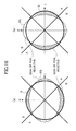
- FIGS. 16(a) and (b) are schematic diagrams illustrating relationships between the average amplitude of an IQ signal and the sign of the power difference PD on an IQ plane.
- FIGS. 16(a) and 16(b) illustrate the case where the phase difference between the in-phase component I" and the quadrature component Q" is larger than 90 degrees and the case where the phase difference is smaller than 90 degrees, respectively.
- the sign of the power difference PD obtained from subtracting the power value PB from the average power PV is determined based on a relationship between the perfect circle S and the ellipse SP. Specifically, in the case of FIG. 16(a), the value of the power difference PD is substantially invariably positive in an area A (first and third quadrants), and is substantially invariably negative in an area B (second and fourth quadrants).
- the quadrature skew error detecting section 350 inverts the sign of the power difference PD and integrates the sign-inverted power difference PD when signal points of an IQ signal are present in the first and third quadrants, and integrates the power difference PD as it is when the signal points are present in the second and fourth quadrants. Since the sign of the power difference PD to be integrated is caused to be substantially invariably negative, the quadrature skew error detecting section 350 outputs quadrature skew error information so that the quadrature skew converges to a small value.
- the value of the power difference PD is substantially invariably negative in the area A (first and third quadrants), and is substantially invariably positive in the area B (second and fourth quadrants).
- the quadrature skew error detecting section 350 inverts the sign of the power difference PD and integrates the sign-inverted power difference PD when signal points of an IQ signal are present in the first and third quadrants, and integrates the power difference PD as it is when the signal points are present in the second and fourth quadrants. Since the sign of the power difference PD to be integrated is caused to be substantially invariably positive, the quadrature skew error detecting section 350 outputs quadrature skew error information so that the quadrature skew converges to a small value.
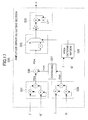
- FIG. 17 is a block diagram illustrating an exemplary configuration of the amplitude error detecting section 330 of FIG. 13.
- the amplitude error detecting section 330 comprises power calculating sections 331 and 339, a sign determining section 332, an LPF 335, an area determining section 336, an averager 337, and a subtractor 338.
- the power calculating sections 331 and 339 have the same configuration as that of the power calculating section 51 of FIG. 9.
- the power calculating section 339 obtains and adds power values of the in-phase component I and the quadrature component Q of an IQ signal before amplitude correction, and outputs the result as a power value PAA to the averager 337.
- the averager 337 averages the power value PAA, and outputs a resultant average power PVA to the subtractor 338.
- the power calculating section 331 obtains and adds power values of the in-phase component I' and the quadrature component Q', and outputs the result as a power value PBA to the subtractor 338.
- the subtractor 338 subtracts the power value PBA from the average power PVA, and outputs the result as a power difference PDA to the sign determining section 332.
- the area determining section 336 outputs "1" when the absolute value of the in-phase component I' is larger than the absolute value of the quadrature component Q', and "0" when the absolute value of the quadrature component Q' is larger than the absolute value of the in-phase component 1', as an area determination signal to the sign determining section 332.
- the sign determining section 332 has substantially the same configuration as that of the sign determining section 52 of FIG. 9.
- the sign determining section 332 inverts the sign of the power difference PDA when the area determination signal is "0", and does not change the sign of the power difference PDA when the area determination signal is "1", before outputting the power difference PDA to the LPF 335.
- the LPF 335 integrates the output of the sign determining section 332, i.e., accumulates the output of the sign determining section 332 after gain adjustment, and outputs the result as an in-phase amplitude error magnification factor ⁇ .
- FIGS. 18(a ) and 18(b) are schematic diagrams illustrating relationships between the average amplitude of an IQ signal and the sign of the power difference PDA on an IQ plane.
- FIG. 18(a) illustrates the case where the amplitude of the in-phase component I' is larger than the amplitude of the quadrature component Q'.
- FIG. 18(b) illustrates the case where the amplitude of the quadrature component Q' is larger than the amplitude of the in-phase component I'.
- the average amplitude of an IQ signal having these as components thereof is represented by ellipses SG of FIGS. 18(a) and 18(b).
- the radius of a perfect circle S of FIGS. 18(a) and 18(b) is the square root of the average power PVA of the IQ signal.
- the sign of the power difference PDA obtained by subtracting the power value PBA from the average power PVA is determined based on a relationship between the perfect circle S and the ellipse SG. Specifically, in the case of FIG. 18(a) , the value of the power difference PDA is substantially invariably negative in an area A (area of
- the area determining section 336 outputs "1" as the area determination signal, so that the amplitude error detecting section 330 integrates the power difference PDA as it is.
- the area determining section 336 outputs "0" as the area determination signal, so that the amplitude error detecting section 330 inverts the sign of the power difference PDA and integrates the sign-inverted power difference PDA.
- the amplitude error detecting section 330 outputs an in-phase amplitude error magnification factor ⁇ so that a difference in amplitude between the in-phase component I' and the quadrature component Q' is reduced.
- the value of the power difference PDA is substantially invariably positive in an area A (area of
- the amplitude error detecting section 330 integrates the power difference PDA as it is when signal points of an IQ signal are present in the are of
- the amplitude error detecting section 330 outputs an in-phase amplitude error magnification factor ⁇ so that a difference in amplitude between the in-phase component I' and the quadrature component Q' is decreased.
- FIG. 19 is a diagram illustrating an area which needs to be determined, when detection of a quadrature skew error and an amplitude error is performed.
- FIG. 19(a) relates to detection of a quadrature skew error
- FIG. 19(b) relates to detection of an amplitude error.
- the entirety of FIG. 19(b) may be rotated by 45 degrees, and quadrant determination may be performed as in FIG. 19(a) instead of area determination in FIG. 19(b) .
- FIG. 20 is a block diagram illustrating a variation of the configuration of the amplitude/quadrature skew error compensating section of FIG. 17.
- An amplitude/quadrature skew error compensating section 415 of FIG. 20 is configured so that the in-phase component I" and the quadrature component Q" are input in place of the in-phase component I' and the quadrature component Q' to the amplitude error detecting section 330 in the amplitude/quadrature skew error compensating section 315 of FIG. 13.
- the amplitude/quadrature skew error compensating section 415 is the same as the amplitude/quadrature skew error compensating section 315.
- the amplitude/quadrature skew error compensating section 415 since the same signal is input to the power calculating section 351 of FIG. 14 and the power calculating section 331 of FIG. 17, either the power calculating section 351 or the power calculating section 331 may be shared. Specifically, the amplitude/quadrature skew error compensating section 415 may comprise only one of the power calculating sections 351 and 331, and the output of the one power calculating section may be input to the subtractors 338 and 358.
- either the power calculating section 359 or the power calculating section 339 may be shared. Further, either the averager 357 or the averager 337 may be shared, and either the subtractor 358 or the subtractor 338 may be shared.
- the power calculating sections 359 and 339 and the averagers 357 and 337 may not be provided, and the reference power P' may be input to the subtractors 358 and 338.
- the present invention can correctly perform amplitude/quadrature skew error correction without a malfunction, and therefore, is useful for a demodulation device for demodulating a digital modulated signal, and the like.
Landscapes
- Engineering & Computer Science (AREA)
- Computer Networks & Wireless Communication (AREA)
- Signal Processing (AREA)
- Digital Transmission Methods That Use Modulated Carrier Waves (AREA)
- Superheterodyne Receivers (AREA)
Applications Claiming Priority (2)
| Application Number | Priority Date | Filing Date | Title |
|---|---|---|---|
| JP2005169624 | 2005-06-09 | ||
| PCT/JP2006/310887 WO2006132118A1 (fr) | 2005-06-09 | 2006-05-31 | Appareil de compensation d’erreur d’amplitude et appareil de compensation d’erreur d’orthogonalité |
Publications (1)
| Publication Number | Publication Date |
|---|---|
| EP1777906A1 true EP1777906A1 (fr) | 2007-04-25 |
Family
ID=37498320
Family Applications (1)
| Application Number | Title | Priority Date | Filing Date |
|---|---|---|---|
| EP06756819A Withdrawn EP1777906A1 (fr) | 2005-06-09 | 2006-05-31 | Appareil de compensation d erreur d amplitude et appareil de compensation d erreur d orthogonalité |
Country Status (4)
| Country | Link |
|---|---|
| US (1) | US7456683B2 (fr) |
| EP (1) | EP1777906A1 (fr) |
| JP (2) | JP4495210B2 (fr) |
| WO (1) | WO2006132118A1 (fr) |
Cited By (3)
| Publication number | Priority date | Publication date | Assignee | Title |
|---|---|---|---|---|
| US7456683B2 (en) * | 2005-06-09 | 2008-11-25 | Panasonic Corporation | Amplitude error compensating device and quadrature skew error compensating device |
| EP2688262A4 (fr) * | 2011-03-14 | 2014-08-20 | Furukawa Electric Co Ltd | Démodulateur en quadrature |
| DE102023103646A1 (de) | 2023-02-15 | 2024-08-22 | Schaeffler Technologies AG & Co. KG | Verfahren zur dynamischen Korrektur der Orthogonalität von zwei wellenförmigen Drehwinkelsignalen |
Families Citing this family (182)
| Publication number | Priority date | Publication date | Assignee | Title |
|---|---|---|---|---|
| JP4998207B2 (ja) * | 2007-10-29 | 2012-08-15 | 株式会社Kddi研究所 | 同相直交不整合を補償する通信装置及び方法 |
| US8279975B2 (en) * | 2009-12-14 | 2012-10-02 | Motorola Solutions, Inc. | Method to suppress undesired sidebands in a receiver |
| US20130023033A1 (en) | 2010-03-29 | 2013-01-24 | The Trustees Of The University Of Pennsylvania | Pharmacologically induced transgene ablation system |
| US9315825B2 (en) | 2010-03-29 | 2016-04-19 | The Trustees Of The University Of Pennsylvania | Pharmacologically induced transgene ablation system |
| CN102209055B (zh) * | 2010-03-30 | 2014-10-01 | 富士通株式会社 | 用于相移键控信号的自适应盲均衡方法、均衡器及接收机 |
| WO2012007458A1 (fr) | 2010-07-12 | 2012-01-19 | Universidad Autónoma De Barcelona | Composition de thérapie génique destinée à être utilisée dans le traitement du diabète |
| WO2012153373A1 (fr) * | 2011-05-10 | 2012-11-15 | パナソニック株式会社 | Dispositif de compensation d'erreur d'amplitude/d'orthogonalité |
| US8750442B2 (en) * | 2011-12-08 | 2014-06-10 | Nec Corporation | Digital receiver and waveform compensation method |
| US8594514B2 (en) * | 2011-12-28 | 2013-11-26 | Infinera Corporation | Phase-modulated transmission control using embedded control symbols |
| JP6116807B2 (ja) * | 2012-03-07 | 2017-04-19 | 古河電気工業株式会社 | レーダ装置およびレーダ装置の調整方法 |
| EP2692868A1 (fr) | 2012-08-02 | 2014-02-05 | Universitat Autònoma De Barcelona | Vecteurs viraux adéno-associés (AAV) utiles pour la transduction de tissu adipeux |
| US9042487B2 (en) | 2012-08-13 | 2015-05-26 | Texas Instruments Incorporated | Blind I/Q mismatch compensation with receiver non-linearity |
| SI2984166T1 (sl) | 2013-03-15 | 2020-09-30 | The Trustees Of The University Of Pennsylvania | Sestavki za zdravljenje MPSI |
| JP6186882B2 (ja) * | 2013-05-21 | 2017-08-30 | トヨタ自動車株式会社 | 物体変位検知装置、及び物体変位検知方法 |
| RS60902B1 (sr) | 2014-03-09 | 2020-11-30 | Univ Pennsylvania | Kompozicije korisne u lečenju nedostatka ornitinske transkarbamilaze (otc) |
| JP6318774B2 (ja) * | 2014-03-28 | 2018-05-09 | トヨタ自動車株式会社 | 物体変位量検知信号処理装置 |
| WO2015164723A1 (fr) | 2014-04-25 | 2015-10-29 | The Trustees Of The University Of Pennsylvania | Procédés et compositions pour le traitement du cancer du sein métastatique et d'autres cancers dans le cerveau |
| ES2876409T3 (es) | 2014-04-25 | 2021-11-12 | Univ Pennsylvania | Variantes del RLBD y su uso en composiciones para reducir los niveles de colesterol |
| EP3242945B1 (fr) | 2015-01-07 | 2021-09-01 | Universitat Autònoma de Barcelona | Construction génique à vecteur unique comprenant des gènes de l'insuline et de la glucokinase |
| US10676726B2 (en) | 2015-02-09 | 2020-06-09 | Duke University | Compositions and methods for epigenome editing |
| EP3288594B1 (fr) | 2015-04-27 | 2022-06-29 | The Trustees of The University of Pennsylvania | Système de vecteur aav double pour la correction médiée par crispr/cas9 d'une maladie humaine |
| EA201792500A1 (ru) | 2015-05-13 | 2018-04-30 | Дзе Трастиз Оф Дзе Юниверсити Оф Пенсильвания | Aav-опосредованная экспрессия антител против гриппа и способы их использования |
| WO2017015637A1 (fr) | 2015-07-22 | 2017-01-26 | Duke University | Criblage à haut rendement d'une fonction d'élément de régulation à l'aide de technologies d'édition de l'épigénome |
| EP3332012A4 (fr) | 2015-08-06 | 2019-01-16 | The Trustees of The University of Pennsylvania | Glp-1 et son utilisation dans des compositions pour traiter des maladies métaboliques |
| EP3341727B1 (fr) | 2015-08-25 | 2022-08-10 | Duke University | Compositions et procédés d'amélioration de la spécificité dans l'ingénierie génomique à l'aide d'endonucléases guidées par arn |
| HK1257024A1 (zh) | 2015-08-31 | 2019-10-11 | 宾夕法尼亚大学 | 用於治疗伴侣动物的aav-epo |
| CN108291216B (zh) | 2015-09-24 | 2022-09-16 | 宾夕法尼亚州大学信托人 | 用于治疗补体介导的疾病的组合物和方法 |
| US11273227B2 (en) | 2015-10-09 | 2022-03-15 | The Trustees Of The University Of Pennsylvania | Compositions and methods useful in treating Stargardt's disease and other ocular disorders |
| EP4089175A1 (fr) | 2015-10-13 | 2022-11-16 | Duke University | Ingénierie génomique avec systèmes crispr de type i dans des cellules eucaryotes |
| HK1257801A1 (zh) | 2015-10-28 | 2019-11-01 | 宾夕法尼亚州大学信托人 | 用於基因治疗的腺伴随病毒载体的鞘内给药 |
| IL303850A (en) | 2015-12-11 | 2023-08-01 | Univ Pennsylvania | Gene therapy for treating familial hypercholesterolemia |
| US11090392B2 (en) | 2015-12-14 | 2021-08-17 | The Trustees Of The University Of Pennsylvania | Gene therapy for ocular disorders |
| CA3007330A1 (fr) | 2015-12-14 | 2017-06-22 | The Trustees Of The University Of Pennsylvania | Composition pour le traitement du syndrome de crigler-najjar |
| EP3411488A1 (fr) | 2016-02-03 | 2018-12-12 | The Trustees Of The University Of Pennsylvania | Thérapie génique pour traiter la mucopolysaccharidose de type i |
| US20190127713A1 (en) | 2016-04-13 | 2019-05-02 | Duke University | Crispr/cas9-based repressors for silencing gene targets in vivo and methods of use |
| EP3442597A1 (fr) | 2016-04-15 | 2019-02-20 | The Trustees Of The University Of Pennsylvania | Thérapie génique pour le traitement de l'hémophilie b |
| JP7046828B2 (ja) | 2016-04-15 | 2022-04-04 | ザ・トラステイーズ・オブ・ザ・ユニバーシテイ・オブ・ペンシルベニア | 滲出型加齢性黄斑変性の治療のための組成物 |
| IL305449B2 (en) | 2016-04-15 | 2026-01-01 | Univ Pennsylvania | Gene therapy for the treatment of mucocutaneous type ii diabetes |
| US11401527B2 (en) | 2016-04-17 | 2022-08-02 | The Trustees Of The University Of Pennsylvania | Compositions and methods useful for prophylaxis of organophosphates |
| US11197936B2 (en) | 2016-07-08 | 2021-12-14 | The Trustees Of The University Of Pennsylvania | Methods and compositions for treatment of disorders and diseases involving RDH12 |
| WO2018017754A1 (fr) | 2016-07-19 | 2018-01-25 | Duke University | Applications thérapeutiques de l'édition du génome fondée sur cpf1 |
| WO2018022511A1 (fr) | 2016-07-25 | 2018-02-01 | The Trustees Of The University Of Pennsylvania | Compositions comprenant un variant de la lécithine-cholestérol-acyl-transférase et leurs utilisations |
| JP6603639B2 (ja) * | 2016-09-21 | 2019-11-06 | 株式会社東芝 | 送受信回路、送受信機および信号時間差補正方法 |
| CA3049915A1 (fr) | 2017-01-31 | 2018-08-09 | Stephen YOO | Traitement de la mucopolysaccharidose i avec une alpha-l-iduronidase glycosylee entierement humaine (idua) |
| US11554147B2 (en) | 2017-02-20 | 2023-01-17 | The Trustees Of The University Of Pennsylvania | Gene therapy for treating familial hypercholesterolemia |
| CA3052487A1 (fr) | 2017-02-28 | 2018-09-07 | The Trustees Of The University Of Pennsylvania | Vaccins contre la grippe bases sur des vecteurs aav |
| JOP20190200A1 (ar) | 2017-02-28 | 2019-08-27 | Univ Pennsylvania | تركيبات نافعة في معالجة ضمور العضل النخاعي |
| JP7455579B2 (ja) | 2017-02-28 | 2024-03-26 | ザ・トラステイーズ・オブ・ザ・ユニバーシテイ・オブ・ペンシルベニア | 新規アデノ随伴ウイルス(aav)クレードfベクター及びその用途 |
| BR112019017327A2 (pt) | 2017-03-01 | 2020-04-14 | Univ Pennsylvania | terapia gênica para distúrbios oculares |
| JP2020516291A (ja) | 2017-04-14 | 2020-06-11 | レジェンクスバイオ インコーポレーテッド | ヒト神経細胞又はグリア細胞により生産された組換えヒトイズロン酸−2−スルファターゼ(ids)によるムコ多糖症ii型の治療 |
| WO2018200542A1 (fr) | 2017-04-24 | 2018-11-01 | The Trustees Of The University Of Pennsylvania | Thérapie génique pour troubles oculaires |
| KR102719222B1 (ko) | 2017-05-11 | 2024-10-21 | 더 트러스티스 오브 더 유니버시티 오브 펜실베니아 | 신경 세로이드 지질갈색소증에 대한 유전자 요법 |
| EP3630986B1 (fr) | 2017-05-31 | 2026-03-25 | The Trustees of The University of Pennsylvania | Thérapie génique destinée au traitement de troubles des peroxysomes |
| US11827898B2 (en) | 2017-06-14 | 2023-11-28 | The Trustees Of The University Of Pennsylvania | Gene therapy for ocular disorders |
| MA50016A (fr) | 2017-07-06 | 2020-07-08 | Univ Pennsylvania | Thérapie génique médiée par aav9 pour traiter la mucopolysaccharidose de type i |
| TWI835747B (zh) | 2017-09-22 | 2024-03-21 | 賓州大學委員會 | 用於治療黏多醣病 ii 型之基因治療 |
| EP3687565A1 (fr) | 2017-09-27 | 2020-08-05 | Alexion Pharmaceuticals, Inc. | Méthodes d'amélioration de la fonction cardio-vasculaire et de traitement d'une maladie cardio-vasculaire à l'aide d'une ecto-nucléotide pyrophosphatase/phosphodiestérase recombinante |
| AU2018350990A1 (en) | 2017-10-18 | 2020-05-21 | Regenxbio Inc. | Treatment of ocular diseases and metastatic colon cancer with human post-translationally modified VEGF-Trap |
| BR112020007405A2 (pt) | 2017-10-18 | 2020-12-08 | Regenxbio Inc. | Produtos terapêuticos de anticorpo pós-translacionalmente modificados totalmente humanos |
| US11435238B2 (en) * | 2017-11-24 | 2022-09-06 | Mitsubishi Electric Cornoration | Temperature detection device and temperature detection method |
| KR20200104864A (ko) | 2017-11-30 | 2020-09-04 | 더 트러스티스 오브 더 유니버시티 오브 펜실바니아 | 뮤코다당류증 iiib형에 대한 유전자 요법 |
| KR102823833B1 (ko) | 2017-11-30 | 2025-06-23 | 더 트러스티스 오브 더 유니버시티 오브 펜실베니아 | 뮤코다당류증 iiia형에 대한 유전자 요법 |
| US12558434B2 (en) | 2018-02-20 | 2026-02-24 | The Trustees Of The University Of Pennsylvania | Compositions for treatment of wet age-related macular degeneration |
| MX2020008932A (es) | 2018-02-27 | 2020-10-01 | Univ Pennsylvania | Novedosos vectores de virus adenoasociado (aav), vectores de aav que tienen una desamidacion reducida de la capside y usos de estos. |
| US12460226B2 (en) | 2018-04-16 | 2025-11-04 | The Trustees Of The University Of Pennsylvania | Compositions and methods for treating duchenne muscular dystrophy |
| WO2019212922A1 (fr) | 2018-04-29 | 2019-11-07 | Regenxbio Inc. | Systèmes et procédés de spectrophotométrie pour la détermination de contenu génomique, de contenu de capside et de rapports complets/vides de particules de virus adéno-associés |
| WO2019212921A1 (fr) | 2018-04-29 | 2019-11-07 | Regenxbio Inc. | Procédé de clarification évolutif pour la production d'aav recombinants |
| WO2019241535A2 (fr) | 2018-06-14 | 2019-12-19 | Regenxbio Inc. | Chromatographie d'échange d'anions pour la production de vaa recombinants |
| EP3833745A1 (fr) | 2018-08-10 | 2021-06-16 | REGENXBIO Inc. | Procédé évolutif pour la production d'aav recombinants |
| JP2022514112A (ja) | 2018-10-15 | 2022-02-09 | リジェネクスバイオ インコーポレイテッド | 複製欠損型ウイルスベクター及びウイルスの感染性を測定するための方法 |
| UY38407A (es) | 2018-10-15 | 2020-05-29 | Novartis Ag | Anticuerpos estabilizadores de trem2 |
| EP3672070A1 (fr) * | 2018-12-19 | 2020-06-24 | Nxp B.V. | Dispositif de communication et procédé de commande d'un dispositif de communication |
| TW202045728A (zh) | 2019-02-26 | 2020-12-16 | 賓州大學委員會 | 用於治療克拉培氏病之組成物 |
| EP4667578A3 (fr) | 2019-04-03 | 2026-04-01 | REGENXBIO Inc. | Thérapie génique pour pathologies de l'oeil |
| TW202102526A (zh) | 2019-04-04 | 2021-01-16 | 美商銳進科斯生物股份有限公司 | 重組腺相關病毒及其用途 |
| HUE064411T2 (hu) | 2019-04-11 | 2024-03-28 | Regenxbio Inc | Méretkizárásos kromatográfiás módszerek rekombináns adeno-asszociált víruskészítmények jellemzésére |
| US20220143115A1 (en) | 2019-04-19 | 2022-05-12 | Regenxbio Inc. | Adeno-Associated Virus Vector Formulations and Methods |
| KR20220012231A (ko) | 2019-04-24 | 2022-02-03 | 리젠엑스바이오 인크. | 완전-인간 번역 후 변형된 항체 치료제 |
| BR112021021908A2 (pt) | 2019-05-03 | 2022-02-01 | Univ Pennsylvania | Composições úteis no tratamento da leucodistrofia metacromática |
| EP3914720B9 (fr) | 2019-07-10 | 2023-09-27 | Masonic Medical Research Laboratory | Vgll4 avec un élément régulateur cis d'ucp-1 et son procédé d'utilisation |
| US20220251567A1 (en) | 2019-07-10 | 2022-08-11 | Inserm (Institut National De La Santè Et De La Recherche Médicale) | Methods for the treatment of epilepsy |
| JP2022544004A (ja) | 2019-07-26 | 2022-10-17 | リジェネックスバイオ インコーポレイテッド | 操作された核酸調節エレメントならびにその使用方法 |
| WO2021041373A1 (fr) | 2019-08-26 | 2021-03-04 | Regenxbio Inc. | Traitement de la rétinopathie diabétique avec un fab anti-vegf à modification post-traductionnelle complètement humain |
| AU2020362119A1 (en) | 2019-10-07 | 2022-05-26 | Regenxbio Inc. | Adeno-associated virus vector pharmaceutical composition and methods |
| WO2021076600A1 (fr) | 2019-10-14 | 2021-04-22 | Duke University | Compositions comprenant de nouveaux canaux sodiques procaryotes et procédés associés |
| US20230016983A1 (en) | 2019-11-19 | 2023-01-19 | lNSERM (INSTITUT NATIONAL DE LA SANTÉ ET DE LA RECHERCHE MÉDICALE) | Antisense oligonucleotides and thier use for the treatment of cancer |
| MX2022006427A (es) | 2019-11-28 | 2022-09-07 | Regenxbio Inc | "construcciones para terapia génica con microdistrofina y uso de las mismas. |
| WO2021150570A1 (fr) | 2020-01-22 | 2021-07-29 | Regenxbio Inc. | Traitement de la mucopolysaccharidose i avec une alpha-l-iduronidase glycosylée entièrement humaine (idua) |
| DE102020102065B3 (de) | 2020-01-29 | 2021-06-02 | Schaeffler Technologies AG & Co. KG | Kupplungsaktor, Erfassungssystem und Verfahren zur Erfassung einer Winkelposition eines Drehbauteils |
| CA3167741A1 (fr) | 2020-01-29 | 2021-08-05 | Regenxbio Inc. | Traitement de la mucopolysaccharidose ii avec de l'iduronate-2-sulfatase (ids) humaine recombinee produite par des cellules neurales ou gliales humaines |
| DE102020102064B3 (de) | 2020-01-29 | 2021-05-27 | Schaeffler Technologies AG & Co. KG | Kupplungsaktor, Erfassungssystem und Verfahren zur Erfassung einer Winkelposition eines Drehbauteils |
| AR121201A1 (es) | 2020-01-29 | 2022-04-27 | Regenxbio Inc | Tratamiento de mucopolisacaridosis iva |
| DE102020102063B3 (de) | 2020-01-29 | 2021-05-27 | Schaeffler Technologies AG & Co. KG | Kupplungsaktor, Erfassungssystem und Verfahren zur Erfassung einer Winkelposition eines Drehbauteils |
| US20230304034A1 (en) | 2020-05-12 | 2023-09-28 | The Trustees Of The University Of Pennsylvania | Compositions for drg-specific reduction of transgene expression |
| CA3177924A1 (fr) | 2020-05-12 | 2021-11-18 | The Trustees Of The University Of Pennsylvania | Compositions utiles dans le traitement de la maladie de krabbe |
| US20230220069A1 (en) | 2020-06-17 | 2023-07-13 | The Trustees Of The University Of Pennsylvania | Compositions and methods for treatment of gene therapy patients |
| KR20230050336A (ko) | 2020-07-10 | 2023-04-14 | 인스티튜트 내셔널 드 라 싼테 에 드 라 리셰르셰 메디칼르 (인 썸) | 뇌전증을 치료하기 위한 방법과 조성물 |
| US20230265456A1 (en) | 2020-08-10 | 2023-08-24 | Fundacion Para La Investigacion Medica Aplicada | Gene therapy vector expressing cyp27a1 for the treatment of cerebrotendinous xanthomatosis |
| BR112023003310A2 (pt) | 2020-08-24 | 2023-05-02 | Univ Pennsylvania | Vetores virais que codificam fusões de agonistas do receptor de glp-1 e usos dos mesmos no tratamento de doenças metabólicas |
| EP4213890A1 (fr) | 2020-09-15 | 2023-07-26 | RegenxBio Inc. | Lanadelumab vectorisé et administration de celui-ci |
| WO2022060916A1 (fr) | 2020-09-15 | 2022-03-24 | Regenxbio Inc. | Anticorps vectorisés pour thérapie antivirale |
| US20240024508A1 (en) | 2020-10-07 | 2024-01-25 | Regenxbio Inc. | Formulations for suprachoroidal administration such as high viscosity formulations |
| US20230381341A1 (en) | 2020-10-07 | 2023-11-30 | Regenxbio Inc. | Adeno-associated viruses for ocular delivery of gene therapy |
| CA3194861A1 (fr) | 2020-10-07 | 2022-04-14 | Regenxbio Inc. | Formulations pour administration suprachoroidienne, telles que formulations de gel |
| US20230372538A1 (en) | 2020-10-07 | 2023-11-23 | Regenxbio Inc. | Formulations for suprachoroidal administration such as formulations with aggregate formation |
| WO2022076750A2 (fr) | 2020-10-07 | 2022-04-14 | Regenxbio Inc. | Virus adéno-associés recombinants pour administration musculaire ou dans le snc |
| CA3197342A1 (fr) | 2020-10-07 | 2022-04-14 | Regenxbio Inc. | Therapie genique pour manifestations oculaires de maladie cln2 |
| AU2021356684A1 (en) | 2020-10-09 | 2023-05-11 | The Trustees Of The University Of Pennsylvania | Compositions and methods for treatment of fabry disease |
| IL302127A (en) | 2020-10-18 | 2023-06-01 | Univ Pennsylvania | An improved adeno-associated virus (AAV) vector and its uses |
| WO2022094078A1 (fr) | 2020-10-28 | 2022-05-05 | The Trustees Of The University Of Pennsylvania | Compositions utiles dans le traitement du syndrome de rett |
| CN116528892A (zh) | 2020-10-28 | 2023-08-01 | 再生生物股份有限公司 | 用于眼部适应症的载体化抗TNF-α抗体 |
| WO2022094157A1 (fr) | 2020-10-28 | 2022-05-05 | Regenxbio Inc. | Anticorps vectorisés anti-cgrp et anti-récepteur de cgrp et leur administration |
| AU2021369793A1 (en) | 2020-10-29 | 2023-06-08 | The Trustees Of The University Of Pennsylvania | Aav capsids and compositions containing same |
| CN116457373A (zh) | 2020-10-29 | 2023-07-18 | 再生生物股份有限公司 | 用于眼部适应症的载体化TNF-α拮抗剂 |
| US20230390418A1 (en) | 2020-10-29 | 2023-12-07 | Regenxbio Inc. | Vectorized factor xii antibodies and administration thereof |
| TW202237850A (zh) | 2020-12-01 | 2022-10-01 | 賓州大學委員會 | 具有組織特異性靶向基序的新穎構成物及含有其之組成物 |
| EP4263841A1 (fr) | 2020-12-16 | 2023-10-25 | REGENXBIO Inc. | Procédé de production d'une particule de virus adéno-associé recombinant |
| US20240091382A1 (en) | 2020-12-23 | 2024-03-21 | Vivet Therapeutics | Minimal bile acid inducible promoters for gene therapy |
| WO2022147087A1 (fr) | 2020-12-29 | 2022-07-07 | Regenxbio Inc. | Compositions de thérapie génique à base d'anticorps spécifiques de tau, procédés et utilisations associées |
| EP4281568A1 (fr) | 2021-01-21 | 2023-11-29 | RegenxBio Inc. | Production améliorée de polypeptides et de virus recombinés |
| WO2022165313A1 (fr) | 2021-02-01 | 2022-08-04 | Regenxbio Inc. | Thérapie génique de céroïdes-lipofuscinoses neuronales |
| BR112023016075A2 (pt) | 2021-02-10 | 2023-11-21 | Regenxbio Inc | Método para tratar hepatoesplenomegalia, método de distribuição de um raav que codifica hids, método para tratar um sujeito humano, método de tratamento de um sujeito humano, método para determinar a eficácia do tratamento, método para identificar um sujeito como tendo mps ii |
| AR125406A1 (es) | 2021-04-23 | 2023-07-12 | Univ Pennsylvania | Nuevas composiciones con motivos selectivos para el cerebro y composiciones que las contienen |
| KR20240004564A (ko) | 2021-04-26 | 2024-01-11 | 리젠엑스바이오 인크. | 디스트로핀병증의 치료를 위한 마이크로디스트로핀 유전자 치료법 투여 |
| WO2022235614A2 (fr) | 2021-05-04 | 2022-11-10 | Regenxbio Inc. | Nouveaux vecteurs aav et procédés et utilisations associés |
| WO2022241030A1 (fr) | 2021-05-11 | 2022-11-17 | Regenxbio Inc. | Traitement de la dystrophie musculaire de duchenne et combinaisons correspondantes |
| CA3226402A1 (fr) | 2021-07-19 | 2023-01-26 | Dounia ABBADI | Compositions de vecteurs viraux adeno-associes et methodes de promotion de la regeneration musculaire |
| AU2022313258A1 (en) | 2021-07-19 | 2024-02-08 | New York University | Auf1 combination therapies for treatment of muscle degenerative disease |
| EP4409010A1 (fr) | 2021-10-02 | 2024-08-07 | The Trustees of The University of Pennsylvania | Nouvelles capsides de vaa et compositions les contenant |
| WO2023060113A1 (fr) | 2021-10-05 | 2023-04-13 | Regenxbio Inc. | Compositions et procédés de production d'aav recombinants |
| CN118202060A (zh) | 2021-10-05 | 2024-06-14 | 再生生物股份有限公司 | 用于重组aav生产的组合物和方法 |
| WO2023060272A2 (fr) | 2021-10-07 | 2023-04-13 | Regenxbio Inc. | Virus adéno-associés recombinants pour administration tropique au snc |
| WO2023060269A1 (fr) | 2021-10-07 | 2023-04-13 | Regenxbio Inc. | Virus adéno-associés recombinants pour administration ciblée |
| EP4423285A1 (fr) | 2021-10-28 | 2024-09-04 | RegenxBio Inc. | Éléments régulateurs d'acides nucléiques modifiés, procédés et utilisations de ceux-ci |
| WO2023087019A2 (fr) | 2021-11-15 | 2023-05-19 | The Trustees Of The University Of Pennsylvania | Compositions pour la réduction spécifique de drg de l'expression de transgènes |
| WO2023102517A1 (fr) | 2021-12-02 | 2023-06-08 | The Trustees Of The University Of Pennsylvania | Compositions et méthodes de traitement de la maladie de fabry |
| US20250177495A1 (en) | 2022-01-10 | 2025-06-05 | The Trustees Of The University Of Pennsylvania | Compositions useful in treatment of metachromatic leukodystrophy |
| US20250144243A1 (en) | 2022-01-25 | 2025-05-08 | The Trustees Of The University Of Pennsylvania | Aav capsids for improved heart transduction and detargeting of liver |
| EP4493226A1 (fr) | 2022-03-13 | 2025-01-22 | RegenxBio Inc. | Promoteurs spécifiques à un muscle modifiés |
| WO2023183623A1 (fr) | 2022-03-25 | 2023-09-28 | Regenxbio Inc. | Thérapie génique du virus adéno-associé à facteur de nécrose tumorale alpha dominant-négatif |
| TW202345913A (zh) | 2022-04-06 | 2023-12-01 | 美商銳進科斯生物股份有限公司 | 用於脈絡膜上投與之調配物諸如凝膠調配物 |
| CA3247507A1 (fr) | 2022-04-06 | 2023-10-12 | Regenxbio Inc. | Composition pharmaceutique comprenant un vecteur de virus adéno-associé (vaa) recombinant avec une cassette d'expression codant un transgène pour administration suprachoroïdienne |
| TW202404651A (zh) | 2022-04-06 | 2024-02-01 | 美商銳進科斯生物股份有限公司 | 用於脈絡膜上投與之調配物諸如形成聚集體之調配物 |
| JP2025512969A (ja) | 2022-04-06 | 2025-04-22 | ザ・トラステイーズ・オブ・ザ・ユニバーシテイ・オブ・ペンシルベニア | Her2陽性転移性乳がん及び他のがんを治療するための組成物及び方法 |
| US20250250326A1 (en) | 2022-04-06 | 2025-08-07 | The Trustees Of The University Of Pennsylvania | Passive immunization with anti-aav neutralizing antibodies to prevent off-target transduction of intrathecally delivered aav vectors |
| WO2023201277A1 (fr) | 2022-04-14 | 2023-10-19 | Regenxbio Inc. | Virus adéno-associés recombinants pour administration tropique au snc |
| WO2023201308A1 (fr) | 2022-04-14 | 2023-10-19 | Regenxbio Inc. | Thérapie génique pour le traitement d'une maladie oculaire |
| US20250277004A1 (en) | 2022-04-18 | 2025-09-04 | Regenxbio Inc. | Hybrid aav capsids |
| EP4518972A2 (fr) | 2022-05-03 | 2025-03-12 | RegenxBio Inc. | Anticorps anti-complément vectorisés et agents de complément et leur administration |
| US20250288697A1 (en) | 2022-05-03 | 2025-09-18 | Regenxbio Inc. | Vectorized anti-tnf-alpha inhibitors for ocular indications |
| US20250353883A1 (en) | 2022-05-06 | 2025-11-20 | Novartis Ag | Novel recombinant aav vp2 fusion polypeptides |
| WO2023239627A2 (fr) | 2022-06-08 | 2023-12-14 | Regenxbio Inc. | Méthodes de production d'aav recombinant |
| IL317874A (en) | 2022-06-24 | 2025-02-01 | Tune Therapeutics Inc | Compounds, systems and methods for reducing low density lipoproteins through targeted gene suppression |
| WO2024015966A2 (fr) | 2022-07-15 | 2024-01-18 | The Trustees Of The University Of Pennsylvania | Vaa recombinants ayant des capsides de clade d et de clade e de vaa et compositions les contenant |
| EP4558149A1 (fr) | 2022-07-21 | 2025-05-28 | Institut National de la Santé et de la Recherche Médicale | Méthodes et compositions pour le traitement de troubles de la douleur chronique |
| JP2025527658A (ja) | 2022-08-24 | 2025-08-22 | リジェネックスバイオ インコーポレイテッド | 組換えアデノ随伴ウイルス及びその使用 |
| IL319873A (en) | 2022-09-30 | 2025-05-01 | Regenxbio Inc | Treatment of eye diseases with recombinant viral vectors containing anti-VEGF FAB |
| JP2025534666A (ja) | 2022-10-11 | 2025-10-17 | リジェネックスバイオ インコーポレイテッド | 操作された核酸調節エレメントならびにその使用方法 |
| KR20250135916A (ko) | 2022-12-17 | 2025-09-15 | 더 트러스티스 오브 더 유니버시티 오브 펜실베니아 | 심장 및 골격근 특이적 표적화 모티프를 갖는 재조합 aav 돌연변이체 벡터 및 이를 포함하는 조성물 |
| WO2024130070A2 (fr) | 2022-12-17 | 2024-06-20 | The Trustees Of The University Of Pennsylvania | Capsides aav recombinantes avec motifs de ciblage spécifiques du muscle cardiaque et squelettique et leurs utilisations |
| EP4646478A1 (fr) | 2023-01-06 | 2025-11-12 | Institut National de la Santé et de la Recherche Médicale | Administration intraveineuse d'oligonucléotides antisens pour le traitement de la douleur |
| EP4680741A2 (fr) | 2023-03-15 | 2026-01-21 | RegenxBio Inc. | Constructions de thérapie génique à saut d'exon, vecteurs et leurs utilisations |
| WO2024211780A1 (fr) | 2023-04-07 | 2024-10-10 | Regenxbio Inc. | Compositions et procédés pour la production d'aav recombiné |
| EP4694904A2 (fr) | 2023-04-13 | 2026-02-18 | REGENXBIO Inc. | Ciblage de capsides d'aav, méthodes de fabrication et d'utilisation de ceux-ci |
| EP4709866A2 (fr) | 2023-05-07 | 2026-03-18 | REGENXBIO Inc. | Compositions et méthodes de production d'aav recombinant |
| WO2024238853A1 (fr) | 2023-05-16 | 2024-11-21 | Regenxbio Inc. | Virus adéno-associés pour administration oculaire de thérapie génique |
| WO2024238859A1 (fr) | 2023-05-16 | 2024-11-21 | Regenxbio Inc. | Agents inhibiteurs de c5 vectorisés et leur administration |
| AU2024271004A1 (en) | 2023-05-16 | 2026-01-15 | Regenxbio Inc. | Vectorized anti-complement antibodies and administration thereof |
| EP4724085A1 (fr) | 2023-06-12 | 2026-04-15 | The Trustees of The University of Pennsylvania | Thérapie génique à base d'aav pour la mucopolysaccharidose iiib |
| AR133098A1 (es) | 2023-06-29 | 2025-08-27 | Univ Pennsylvania | Aav mutante con motivos dirigidos al sistema nervioso central y composiciones que lo contienen |
| WO2025008406A1 (fr) | 2023-07-04 | 2025-01-09 | Institut National de la Santé et de la Recherche Médicale | Oligonucléotides antisens et leur utilisation pour le traitement du cancer |
| IL326390A (en) | 2023-08-10 | 2026-04-01 | Univ Pennsylvania | Compositions and methods for treating spinal muscular atrophy |
| WO2025075963A1 (fr) | 2023-10-02 | 2025-04-10 | Regenxbio Inc. | Méthodes et formulations pour le traitement de la perte auditive associée à la mucopolysaccharidose de type ii avec de l'iduronate-2-sulfatase humaine recombinée |
| WO2025090962A1 (fr) | 2023-10-25 | 2025-05-01 | Regenxbio Inc. | Compositions et procédés pour la production d'aav recombiné |
| WO2025102034A1 (fr) | 2023-11-10 | 2025-05-15 | The Trustees Of The University Of Pennsylvania | Thérapie génique pour le syndrome de barth |
| WO2025106661A1 (fr) | 2023-11-14 | 2025-05-22 | The Trustees Of The University Of Pennsylvania | Compositions ayant des motifs de ciblage spécifiques des muscles cardiaques et squelettiques et leurs utilisations |
| WO2025129157A1 (fr) | 2023-12-15 | 2025-06-19 | The Trustees Of The University Of Pennsylvania | Thérapie génique pour le traitement de la maladie de canavan |
| WO2025217230A1 (fr) | 2024-04-08 | 2025-10-16 | Regenxbio Inc. | Anticorps anti-complément vectorisés et agents de complément et leur administration |
| WO2025217214A2 (fr) | 2024-04-08 | 2025-10-16 | Regenxbio Inc. | Virus adéno-associés recombinants et leurs utilisations |
| WO2025237990A1 (fr) | 2024-05-14 | 2025-11-20 | Institut National de la Santé et de la Recherche Médicale | Oligonucléotides antisens et leur utilisation pour le traitement de la fibrose pulmonaire |
| WO2026006341A1 (fr) | 2024-06-24 | 2026-01-02 | Regenxbio Inc. | Administration de thérapie génique à base de microdystrophine pour le traitement des dystrophinopathies |
| CN119126040B (zh) * | 2024-09-26 | 2026-04-21 | 电子科技大学 | 一种随机幅度误差下相参mimo雷达信号积累性能的解析评估方法 |
Family Cites Families (14)
| Publication number | Priority date | Publication date | Assignee | Title |
|---|---|---|---|---|
| JPH0353735A (ja) | 1989-07-21 | 1991-03-07 | Fujitsu Ltd | 多値qam復調器における直交度制御方式 |
| JP2853728B2 (ja) | 1994-04-25 | 1999-02-03 | 日本電気株式会社 | ディジタル復調回路 |
| JPH1041992A (ja) * | 1996-07-24 | 1998-02-13 | Nippon Telegr & Teleph Corp <Ntt> | 準同期検波復調装置 |
| JP3439036B2 (ja) | 1996-08-07 | 2003-08-25 | 日本電信電話株式会社 | 直交および振幅誤差補償回路 |
| JP3204239B2 (ja) | 1999-02-18 | 2001-09-04 | 日本電気株式会社 | 復調器 |
| GB2348345B (en) | 1999-01-25 | 2004-04-14 | Nec Corp | Demodulator and demodulation method for demodulating quadrature modulation signals |
| JP3698996B2 (ja) * | 2000-06-23 | 2005-09-21 | 株式会社エヌ・ティ・ティ・ドコモ | 通信システムにおける受信機 |
| EP1168597A1 (fr) | 2000-06-23 | 2002-01-02 | NTT DoCoMo, Inc. | Récepteur en quadrature avec correction d'orthogonalité |
| JP3594019B2 (ja) | 2002-03-06 | 2004-11-24 | 日本電気株式会社 | 自動振幅制御回路 |
| JP2004040678A (ja) * | 2002-07-08 | 2004-02-05 | Hitachi Kokusai Electric Inc | 復調装置 |
| JP2004274288A (ja) * | 2003-03-07 | 2004-09-30 | Hitachi Kokusai Electric Inc | 直交変調装置 |
| JP4184870B2 (ja) * | 2003-06-03 | 2008-11-19 | 株式会社日立国際電気 | 直交変復調装置 |
| JP2005197968A (ja) * | 2004-01-06 | 2005-07-21 | Fujitsu Ltd | 信号処理回路並びに直交復調装置およびその誤差推定方法 |
| EP1777906A1 (fr) * | 2005-06-09 | 2007-04-25 | Matsushita Electric Industrial Co., Ltd. | Appareil de compensation d erreur d amplitude et appareil de compensation d erreur d orthogonalité |
-
2006
- 2006-05-31 EP EP06756819A patent/EP1777906A1/fr not_active Withdrawn
- 2006-05-31 US US11/660,968 patent/US7456683B2/en not_active Expired - Fee Related
- 2006-05-31 JP JP2007504197A patent/JP4495210B2/ja not_active Expired - Fee Related
- 2006-05-31 WO PCT/JP2006/310887 patent/WO2006132118A1/fr not_active Ceased
-
2009
- 2009-12-25 JP JP2009294496A patent/JP2010136399A/ja active Pending
Non-Patent Citations (1)
| Title |
|---|
| See references of WO2006132118A1 * |
Cited By (4)
| Publication number | Priority date | Publication date | Assignee | Title |
|---|---|---|---|---|
| US7456683B2 (en) * | 2005-06-09 | 2008-11-25 | Panasonic Corporation | Amplitude error compensating device and quadrature skew error compensating device |
| EP2688262A4 (fr) * | 2011-03-14 | 2014-08-20 | Furukawa Electric Co Ltd | Démodulateur en quadrature |
| DE102023103646A1 (de) | 2023-02-15 | 2024-08-22 | Schaeffler Technologies AG & Co. KG | Verfahren zur dynamischen Korrektur der Orthogonalität von zwei wellenförmigen Drehwinkelsignalen |
| DE102023103646B4 (de) | 2023-02-15 | 2024-10-10 | Schaeffler Technologies AG & Co. KG | Verfahren zur dynamischen Korrektur der Orthogonalität von zwei wellenförmigen Drehwinkelsignalen |
Also Published As
| Publication number | Publication date |
|---|---|
| JP4495210B2 (ja) | 2010-06-30 |
| US7456683B2 (en) | 2008-11-25 |
| US20080030264A1 (en) | 2008-02-07 |
| JPWO2006132118A1 (ja) | 2009-01-08 |
| WO2006132118A1 (fr) | 2006-12-14 |
| JP2010136399A (ja) | 2010-06-17 |
Similar Documents
| Publication | Publication Date | Title |
|---|---|---|
| EP1777906A1 (fr) | Appareil de compensation d erreur d amplitude et appareil de compensation d erreur d orthogonalité | |
| JP4376689B2 (ja) | 直交変調システム | |
| JP3826147B2 (ja) | デジタル直角変調器 | |
| CN102598615B (zh) | 准相干检波方式的载波恢复电路以及解调电路 | |
| JP5046114B2 (ja) | 多値qam復調装置とその復調方法及び無線通信システム | |
| US8588356B2 (en) | Method and device for detecting a phase error of a signal | |
| EP1860770B1 (fr) | Appareil et méthode de compensation de distorsion | |
| US11811565B1 (en) | Demodulation using two modulation schemes in 5G and 6G | |
| JPH09275427A (ja) | ジッタ抑圧回路 | |
| EP2547059B1 (fr) | Transmetteur incluant l'étalonnage d'un modulateur en phase/quadrature (I/Q) et procédés associés | |
| JPH11331291A (ja) | 自動利得制御方法および自動利得制御を備えた復調装置 | |
| KR20010003137A (ko) | 위상잡음에 따른 위상회전오류 극복을 위한 결정영역 수정회로 | |
| JP2011029717A (ja) | 受信機 | |
| JP4438204B2 (ja) | ディジタル復調装置 | |
| JP4698331B2 (ja) | 送信装置 | |
| JP4361514B2 (ja) | 変調型式識別方法、変調型式識別回路および復調装置 | |
| JP3869976B2 (ja) | 高周波電力増幅装置 | |
| JP3541890B2 (ja) | 復調装置 | |
| JP2025030158A (ja) | 位相制御装置および位相制御方法 | |
| EP2053739A1 (fr) | Dispositif agc numérique | |
| JP2004364131A (ja) | 位相変調信号復調装置及び復調方法 | |
| JP2010171512A (ja) | 無線受信機における誤差補正回路及び誤差補正方法 | |
| JP2012222369A (ja) | 無線送信装置および同装置における直交変調誤差補正方法 | |
| JP2004266777A (ja) | 位相検出方法と装置およびそれを利用した受信装置 |
Legal Events
| Date | Code | Title | Description |
|---|---|---|---|
| PUAI | Public reference made under article 153(3) epc to a published international application that has entered the european phase |
Free format text: ORIGINAL CODE: 0009012 |
|
| 17P | Request for examination filed |
Effective date: 20070213 |
|
| AK | Designated contracting states |
Kind code of ref document: A1 Designated state(s): AT BE BG CH CY CZ DE DK EE ES FI FR GB GR HU IE IS IT LI LT LU LV MC NL PL PT RO SE SI SK TR |
|
| AX | Request for extension of the european patent |
Extension state: AL BA HR MK YU |
|
| DAX | Request for extension of the european patent (deleted) | ||
| RBV | Designated contracting states (corrected) |
Designated state(s): DE FR GB |
|
| RAP1 | Party data changed (applicant data changed or rights of an application transferred) |
Owner name: PANASONIC CORPORATION |
|
| STAA | Information on the status of an ep patent application or granted ep patent |
Free format text: STATUS: THE APPLICATION HAS BEEN WITHDRAWN |
|
| 18W | Application withdrawn |
Effective date: 20110223 |