EP1783345A2 - Brennkraftmaschine mit mechanischer Aufladung - Google Patents
Brennkraftmaschine mit mechanischer Aufladung Download PDFInfo
- Publication number
- EP1783345A2 EP1783345A2 EP06021308A EP06021308A EP1783345A2 EP 1783345 A2 EP1783345 A2 EP 1783345A2 EP 06021308 A EP06021308 A EP 06021308A EP 06021308 A EP06021308 A EP 06021308A EP 1783345 A2 EP1783345 A2 EP 1783345A2
- Authority
- EP
- European Patent Office
- Prior art keywords
- compressor
- internal combustion
- combustion engine
- noise
- pulsation damper
- Prior art date
- Legal status (The legal status is an assumption and is not a legal conclusion. Google has not performed a legal analysis and makes no representation as to the accuracy of the status listed.)
- Granted
Links
Images

Classifications
-
- F—MECHANICAL ENGINEERING; LIGHTING; HEATING; WEAPONS; BLASTING
- F02—COMBUSTION ENGINES; HOT-GAS OR COMBUSTION-PRODUCT ENGINE PLANTS
- F02B—INTERNAL-COMBUSTION PISTON ENGINES; COMBUSTION ENGINES IN GENERAL
- F02B39/00—Component parts, details, or accessories relating to, driven charging or scavenging pumps, not provided for in groups F02B33/00 - F02B37/00
- F02B39/02—Drives of pumps; Varying pump drive gear ratio
- F02B39/04—Mechanical drives; Variable-gear-ratio drives
-
- F—MECHANICAL ENGINEERING; LIGHTING; HEATING; WEAPONS; BLASTING
- F02—COMBUSTION ENGINES; HOT-GAS OR COMBUSTION-PRODUCT ENGINE PLANTS
- F02B—INTERNAL-COMBUSTION PISTON ENGINES; COMBUSTION ENGINES IN GENERAL
- F02B33/00—Engines characterised by provision of pumps for charging or scavenging
- F02B33/44—Passages conducting the charge from the pump to the engine inlet, e.g. reservoirs
-
- F—MECHANICAL ENGINEERING; LIGHTING; HEATING; WEAPONS; BLASTING
- F02—COMBUSTION ENGINES; HOT-GAS OR COMBUSTION-PRODUCT ENGINE PLANTS
- F02B—INTERNAL-COMBUSTION PISTON ENGINES; COMBUSTION ENGINES IN GENERAL
- F02B77/00—Component parts, details or accessories, not otherwise provided for
- F02B77/11—Thermal or acoustic insulation
- F02B77/13—Acoustic insulation
-
- F—MECHANICAL ENGINEERING; LIGHTING; HEATING; WEAPONS; BLASTING
- F02—COMBUSTION ENGINES; HOT-GAS OR COMBUSTION-PRODUCT ENGINE PLANTS
- F02M—SUPPLYING COMBUSTION ENGINES IN GENERAL WITH COMBUSTIBLE MIXTURES OR CONSTITUENTS THEREOF
- F02M35/00—Combustion-air cleaners, air intakes, intake silencers, or induction systems specially adapted for, or arranged on, internal-combustion engines
- F02M35/12—Intake silencers ; Sound modulation, transmission or amplification
- F02M35/1272—Intake silencers ; Sound modulation, transmission or amplification using absorbing, damping, insulating or reflecting materials, e.g. porous foams, fibres, rubbers, fabrics, coatings or membranes
-
- F—MECHANICAL ENGINEERING; LIGHTING; HEATING; WEAPONS; BLASTING
- F02—COMBUSTION ENGINES; HOT-GAS OR COMBUSTION-PRODUCT ENGINE PLANTS
- F02M—SUPPLYING COMBUSTION ENGINES IN GENERAL WITH COMBUSTIBLE MIXTURES OR CONSTITUENTS THEREOF
- F02M35/00—Combustion-air cleaners, air intakes, intake silencers, or induction systems specially adapted for, or arranged on, internal-combustion engines
- F02M35/12—Intake silencers ; Sound modulation, transmission or amplification
- F02M35/1277—Reinforcement of walls, e.g. with ribs or laminates; Walls having air gaps or additional sound damping layers
-
- F—MECHANICAL ENGINEERING; LIGHTING; HEATING; WEAPONS; BLASTING
- F02—COMBUSTION ENGINES; HOT-GAS OR COMBUSTION-PRODUCT ENGINE PLANTS
- F02M—SUPPLYING COMBUSTION ENGINES IN GENERAL WITH COMBUSTIBLE MIXTURES OR CONSTITUENTS THEREOF
- F02M35/00—Combustion-air cleaners, air intakes, intake silencers, or induction systems specially adapted for, or arranged on, internal-combustion engines
- F02M35/12—Intake silencers ; Sound modulation, transmission or amplification
- F02M35/1288—Intake silencers ; Sound modulation, transmission or amplification combined with or integrated into other devices ; Plurality of air intake silencers
Definitions
- the invention relates to an internal combustion engine with mechanical supercharging, wherein a compressor is supported via connecting elements on the cylinder block and wherein some of the components associated with the compressor are equipped with molded foam or a similar sound-absorbing material for reducing the sound radiation.
- Out JP 06 108 942 is an internal combustion engine with V-shaped cylinder block and compressor charging known.
- the compressor is arranged in the free space between the two rows of cylinders and supported by a configured as a resonator assembly on the cylinder block.
- the arrangement and spatial orientation of the resonator should cause a reduction of the airflow noise.
- JP 04 303124 Another engine with V-shaped cylinder block and compressor supercharging will be described. This opens two bypass lines, which bridge the compressor or the intercooler in a common and operatively connected to the compressor line. This line and the compressor are structurally integrated into a common housing, which is arranged in the free space between the two rows of cylinders and to ensure a reduced sound radiation.
- JP 11-315,724 is an internal combustion engine with compressor supercharging, in which a damping chamber is configured in a bypass line bridging the compressor.
- the outside of the damping chamber is covered with a sound absorbing material, such as glass wool.
- JP 63-309,762 is described a supercharged internal combustion engine having a plurality of assemblies with noise-absorbing elements.
- the inner walls of the air filter housing are clad with components made of molded foam and the compressor is at least partially disposed in a housing, on the insides of which noise-absorbing fabric structures are applied.
- the object of the invention is therefore to reduce in an internal combustion engine with charging the sound emission caused by the compressor by assigning specifically designed components with noise-absorbing properties.
- a pulsation damper to the compressor on the suction side and the pressure side and wherein the compressor, the suction-side pulsation damper and the pressure-side pulsation damper are each covered with noise insulation, each having an inner component made of absorption foam and an outer component made of plastic.
- the inner component of absorption foam alternatively as a separate molding or as a planar structure be designed.
- the outer component made of plastic may alternatively be made in one piece or have a plurality of segments which are joined together by a clip connection, a screw connection or by a tongue and groove connection to a common spatial structure.
- the sound radiation caused by the compressor its associated dampers is substantially reduced by an encapsulation of these noise-generating modules.
- the encapsulation chosen here from lined with foam absorption trays can be produced inexpensively and assembled with little effort. As a result, virtually no compressor noise in the vehicle interior perceptible.
- both the increasingly stringent legal requirements can be met in an advantageous manner and the increasing comfort demands of the vehicle users can be satisfied.
- This technical solution is basically suitable for differently designed internal combustion engines, a preferred application here is the assembly on a side surface of the cylinder block of an engine with cylinders arranged in series.
- a section of an internal combustion engine is shown with mechanical charging.
- a compressor 1 is supported via connecting elements, for example with screws 2 on a cylinder block 3.
- the compressor 1 is on the suction side and the pressure side each associated with a pulsation damper.
- the compressor 1, the suction-side pulsation damper and the pressure-side Pulsationsdämpfer are each covered with a noise insulation.
- This noise insulation has in each case an inner component made of absorption foam and an outer component made of plastic.
- a preferred embodiment of the noise insulation for the pressure-side Pulsationsdämpfer can be seen.
- a sound capsule 4 made of plastic is designed, on whose inner surfaces a dimensionally stable and the associated side surface of the compressor 1 cross absorption foam part 5 is supported.
- the noise insulation for the pressure-side pulsation damper has a further dimensionally stable absorption foam part 6.
- This absorption foam part 6 surrounds in a tubular manner a pressure damper stub 7 which is arranged outside the contour of the first absorption foam part 5.
- the sound pressure capsule 4 associated with the pressure-side pulsation damper and / or the absorption foam part 5 assigned to this noise capsule 4 have openings 8. These breakthroughs 8 screws 2 can be assigned to fasten the compressor 1 on the cylinder block 3.
- a noise insulation for the drive of the compressor 1 can also be configured as a sound capsule made of plastic. On the inner surfaces of such a noise capsule, a dimensionally stable and the belt tensioner area cup-shaped cross-over absorption foam part 9 can be supported, which is shown in Fig. 2.
- a preferred embodiment in which the noise insulation for the main body of the compressor 1 is designed as a plastic noise capsule 10. On the inner surfaces of this noise capsule 10 is a dimensionally stable and the compressor 1 U-shaped cross-absorption foam member 11 is supported.
- the noise insulation for the suction-side pulsation damper is preferably configured as a noise capsule 12 assembled from a plurality of segments of plastic. For this purpose, as shown in FIG. 6, for example, three related segments used.
- the inner surfaces of the segments of the noise capsule 12 are each with Absorption foam lined, which is not shown in detail in the drawing.
- FIGS. 4 to 6 the components mounted with one another and equipped with noise insulation are shown in different views, and FIG. 7 finally shows these components in an exploded view.
Landscapes
- Engineering & Computer Science (AREA)
- Chemical & Material Sciences (AREA)
- Combustion & Propulsion (AREA)
- Mechanical Engineering (AREA)
- General Engineering & Computer Science (AREA)
- Physics & Mathematics (AREA)
- Acoustics & Sound (AREA)
- Supercharger (AREA)
- Soundproofing, Sound Blocking, And Sound Damping (AREA)
- Compressor (AREA)
- Organic Low-Molecular-Weight Compounds And Preparation Thereof (AREA)
Abstract
Description
- Die Erfindung betrifft eine Brennkraftmaschine mit mechanischer Aufladung, wobei ein Kompressor über Verbindungselemente am Zylinderblock abgestützt ist und wobei einige der dem Kompressor zugeordneten Bauteile mit Formschaum oder einem ähnlichen geräuschabsorbierenden Material zur Reduzierung der Schallabstrahlung ausgestattet sind.
- Brennkraftmaschinen mit Aufladung sind in verschiedenartigen Ausführungen bekannt. Dabei wird für zahlreiche Anwendungen eine mechanische Aufladung mittels Kompressor realisiert, um funktionell bedingte Nachteile einer Abgasturboaufladung (z.B. das sog. Turboloch oder eine hohe Temperaturbelastung der Baugruppen) zu vermeiden. Der Kompressor erfordert allerdings einen separaten mechanischen Antrieb. Weiterhin ergeben sich zusätzliche Anforderungen an die Geräuschdämpfung, indem neben der ohnehin notwendigen Dämpfung der Ansauggeräusche des Luftfilters nunmehr ebenfalls eine Reduzierung der vom Kompressor verursachten Schallabstrahlung notwendig ist.
- Aus
JP 06 108 942 - In
JP 04 303124 - Die beiden oben genannten technischen Lösungen sind für Brennkraftmaschinen mit einem V-förmigen Zylinderblock geeignet. Unabhängig von dieser Einschränkung ermöglichen solche schwingungsfähigen Abstützungen oder separaten Gehäuse ohnehin eine lediglich geringe oder auf enge Lastbereiche begrenzte Reduzierung der Schallabstrahlung. Deshalb wurde bereits mehrfach vorgeschlagen, diesbezügliche Konstruktionen mit zusätzlichen Dämpfungsmaterialien auszustatten.
- Gegenstand von
JP 11 - 315 724 - Aus
JP 02 - 064 223 - In
JP 63 - 309 762 - Obwohl somit bereits verschiedenartige technische Lösungen zur Reduzierung der vom Kompressor verursachten Schallabstrahlung verfügbar sind, besteht weiterhin Entwicklungsbedarf, um sowohl die zunehmend strengeren gesetzlichen Festlegungen zu erfüllen als auch den steigenden Komfortanspruch der Fahrzeugnutzer zu befriedigen, weil eine Wahrnehmung von Ladergeräuschen im Fahrzeuginnenraum als unangenehm empfunden wird.
- Aufgabe der Erfindung ist es deshalb, bei einer Brennkraftmaschine mit Aufladung die vom Kompressor bewirkte Schallabstrahlung durch Zuordnung spezifisch ausgestalteter Bauteile mit geräuschabsorbierenden Eigenschaften zu reduzieren.
- Diese Aufgabe wird gelöst, indem dem Kompressor saugseitig und druckseitig ein Pulsationsdämpfer zugeordnet ist und wobei der Kompressor, der saugseitige Pulsationsdämpfer und der druckseitige Pulsationsdämpfer jeweils mit einer Geräuschisolierung umhüllt sind, die jeweils ein inneres Bauteil aus Absorptionsschaum und ein äußeres Bauteil aus Kunststoff aufweist. Dabei kann das innere Bauteil aus Absorptionsschaum alternativ als ein separates Formteil oder als ein flächiges Gebilde ausgestaltet werden. Das äußere Bauteil aus Kunststoff kann alternativ einteilig ausgeführt werden oder mehrere Segmente aufweisen, die durch eine Clipverbindung, eine Verschraubung oder durch eine Nut-Feder-Verbindung zu einem gemeinsamen räumlichen Gebilde zusammengefügt sind. Weitere vorteilhafte Ausgestaltungen sind Gegenstand der abhängigen Ansprüche, deren technische Merkmale im Ausführungsbeispiel näher beschrieben werden.
- Bei einer erfindungsgemäß ausgestalteten Brennkraftmaschine wird die vom Kompressor seinen zugeordneten Dämpfern verursachte Schallabstrahlung durch eine Kapselung dieser Geräusche erzeugenden Baugruppen wesentlich reduziert. Die hierbei gewählte Kapselung aus mit Absorptionsschaum ausgekleideten Schalen kann kostengünstig hergestellt und mit geringem Aufwand montiert werden. Im Ergebnis sind faktisch keine Kompressorgeräusche im Fahrzeuginnenraum wahrnehmbar. Somit können in vorteilhafter Weise sowohl die zunehmend strengeren gesetzlichen Festlegungen erfüllt als auch die steigenden Komfortansprüche der Fahrzeugnutzer befriedigt werden.
- Diese technische Lösung ist grundsätzlich für unterschiedlich konzipierte Brennkraftmaschinen geeignet, eine bevorzugte Anwendung ist hierbei die Montage an einer Seitenfläche vom Zylinderblock eines Motors mit in Reihe angeordneten Zylindern.
- Ein Ausführungsbeispiel der Erfindung ist in der Zeichnung dargestellt und wird nachfolgend beschrieben. Es zeigen:
- Fig. 1
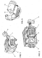
- den grundsätzlichen Aufbau der Dämpfung am druckseitigen Pulsationsdämpfer
- Fig. 2
- die Bauteile aus Fig. 1 in Montageposition mit Zylinderblock und Kompressor
- Fig. 3
- die Bauteile aus Fig. 1 in Montageposition mit saugseitigern Pulsationsdämpfer und Kompressor
- Fig. 4
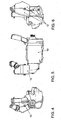
- die miteinander montierten und mit Geräuschisolierung ausgestatteten Bauteile in Seitenansicht von rechts
- Fig. 5
- die Bauteile gemäß Fig. 4 in Vorderansicht
- Fig. 6
- die Bauteile gemäß Fig. 4 in Seitenansicht von links
- Fig. 7
- eine Explosivdarstellung der erfindungsgemäß relevanten Bauteile
- In der Zeichnung ist ein Ausschnitt einer Brennkraftmaschine mit mechanischer Aufladung dargestellt. Hierbei ist ein Kompressor 1 über Verbindungselemente, beispielsweise mit Schrauben 2 an einem Zylinderblock 3 abgestützt. Dem Kompressor 1 ist saugseitig und druckseitig jeweils ein Pulsationsdämpfer zugeordnet. Der Kompressor 1, der saugseitige Pulsationsdämpfer und der druckseitige Pulsationsdämpfer sind jeweils mit einer Geräuschisolierung umhüllt. Diese Geräuschisolierung weist jeweils ein inneres Bauteil aus Absorptionsschaum und ein äußeres Bauteil aus Kunststoff auf.
- Aus Fig. 1 ist eine bevorzugte Ausführung der Geräuschisolierung für den druckseitigen Pulsationsdämpfer ersichtlich. Hierfür ist eine aus Kunststoff bestehende Geräuschkapsel 4 ausgestaltet, an deren Innenflächen ein formstabiles und die zugeordnete Seitenfläche des Kompressors 1 übergreifendes Absorptionsschaumteil 5 abgestützt ist. Gemäß Fig. 1 weist die Geräuschisolierung für den druckseitigen Pulsationsdämpfer ein weiteres formstabiles Absorptionsschaumteil 6 auf. Dieses Absorptionsschaumteil 6 umgreift rohrförmig einen Druckdämpferstutzen 7, der außerhalb der Kontur vom ersten Absorptionsschaumteil 5 angeordnet ist. '
- Die dem druckseitigen Pulsationsdämpfer zugeordnete Geräuschkapsel 4 und/oder das dieser Geräuschkapsel 4 zugeordnete Absorptionsschaumteil 5 weisen Durchbrüche 8 auf. Diesen Durchbrüchen 8 können Schrauben 2 zur Befestigung des Kompressors 1 am Zylinderblock 3 zugeordnet werden.
- Eine Geräuschisolierung für den Antrieb des Kompressors 1 kann ebenfalls als eine aus Kunststoff bestehende Geräuschkapsel ausgestaltet werden. An den Innenflächen einer solchen Geräuschkapsel kann ein formstabiles und den Riemenspannerbereich topfförmig übergreifendes Absorptionsschaumteil 9 abgestützt werden, das in Fig. 2 dargestellt ist.
- Aus Fig. 3 ist eine bevorzugte Ausführung ersichtlich, bei welcher die Geräuschisolierung für den Grundkörper des Kompressors 1 als eine aus Kunststoff bestehende Geräuschkapsel 10 ausgestaltet ist. An den Innenflächen dieser Geräuschkapsel 10 ist ein formstabiles und den Kompressor 1 U-förmig übergreifendes Absorptionsschaumteil 11 abgestützt.
- Die Geräuschisolierung für den saugseitigen Pulsationsdämpfer ist vorzugsweise als eine aus mehreren Segmenten aus Kunststoff zusammengefügte Geräuschkapsel 12 ausgestaltet. Hierfür werden gemäß Fig. 6 beispielsweise drei diesbezügliche Segmente verwendet. Die Innenflächen der Segmente der Geräuschkapsel 12 sind jeweils mit Absorptionsschaum ausgekleidet, der in der Zeichnung allerdings nicht näher dargestellt ist.
- In Fig. 4 bis Fig. 6 sind die miteinander montierten und mit Geräuschisolierung ausgestatteten Bauteile in unterschiedlichen Ansichten dargestellt, Fig. 7 zeigt schließlich diese Bauteile in einer Explosivdarstellung.
Claims (10)
- Brennkraftmaschine mit mechanischer Aufladung, wobei ein Kompressor über Verbindungselemente am Zylinderblock abgestützt ist und wobei einige der dem Kompressor zugeordneten Bauteile mit Formschaum oder einem ähnlichen geräuschabsorbierenden Material zur Reduzierung der Schallabstrahlung ausgestattet sind, dadurch gekennzeichnet,
dass dem Kompressor (1) saugseitig und druckseitig ein Pulsationsdämpfer zugeordnet ist und wobei der Kompressor (1), der saugseitige Pulsationsdämpfer und der druckseitige Pulsationsdämpfer jeweils mit einer Geräuschisolierung umhüllt sind, die jeweils ein inneres Bauteil (5; 9; 11) aus Absorptionsschaum und
ein äußeres Bauteil (4; 10; 12) aus Kunststoff aufweist. - Brennkraftmaschine nach Anspruch 1, dadurch gekennzeichnet,
dass das innere Bauteil aus Absorptionsschaum (5; 9; 11) als ein separates Formteil oder als ein flächiges Gebilde ausgestaltet ist. - Brennkräftmäschine nach Anspruch 1, dadurch gekennzeichnet,
dass das äußere Bauteil (4; 10; 12) aus Kunststoff mehrere Segmente aufweist, die durch eine Clipverbindung, eine Verschraubung oder durch eine Nut-Feder-Verbindung zu einem gemeinsamen räumlichen Gebilde zusammengefügt sind. - Brennkraftmaschine nach Anspruch 1, dadurch gekennzeichnet,
dass am äußeren Bauteil (4; 10; 12) aus Kunststoff und/oder am inneren Bauteil (5; 9; 11) aus Absorptionsschaum Öffnungen (8) ausgestaltet sind, denen Befestigungselemente (2) zuordenbar sind, wobei die Öffnungen (8) mit Schaum abdichtbar sind. - Brennkraftmaschine nach Anspruch 1, dadurch gekennzeichnet,
dass die Geräuschisolierung für den Grundkörper des Kompressors (1) als eine aus Kunststoff bestehende Geräuschkapsel (10) ausgestaltet ist, an deren Innenflächen ein formstabiles und den Kompressor (1) U-förmig übergreifendes Absorptionsschaumteil (11) abgestützt ist. - Brennkraftmaschine nach Anspruch 1, dadurch gekennzeichnet,
dass die Geräuschisolierung für den Antrieb des Kompressors (1) als eine aus Kunststoff bestehende Geräuschkapsel ausgestaltet ist, an deren Innenflächen ein formstabiles und den Riemenspannerbereich topfförmig übergreifendes Absorptionsschaumteil (9) abgestützt ist. - Brennkraftmaschine nach Anspruch 1, dadurch gekennzeichnet,
dass die Geräuschisolierung für den saugseitigen Pulsationsdämpfer als eine aus mehreren Segmenten aus Kunststoff zusammengefügte Geräuschkapsel (12) ausgestaltet ist, wobei die Innenflächen der Segmente jeweils mit Absorptionsschaum ausgekleidet sind. - Brennkraftmaschine nach Anspruch 1, dadurch gekennzeichnet,
dass die Geräuschisolierung für den druckseitigen Pulsationsdämpfer als eine aus Kunststoff bestehende Geräuschkapsel (4) ausgestaltet ist, an deren Innenflächen ein formstabiles und die zugeordnete Seitenfläche des Kompressors (1) übergreifendes Absorptionsschaumteil (5) abgestützt ist. - Brennkraftmaschine nach Anspruch 8, dadurch gekennzeichnet,
dass die dem druckseitigen Pulsationsdämpfer zugeordnete Geräuschkapsel (4) und/oder das dieser Geräuschkapsel (4) zugeordnete Absorptionsschaumteil (5) Durchbrüche (8) aufweisen, denen Schrauben (2) zur Befestigung des Kompressors (1) am Zylinderblock (3) zuordenbar sind. - Brennkraftmaschine nach Anspruch 8, dadurch gekennzeichnet,
dass die Geräuschisolierung für den druckseitigen Pulsationsdämpfer ein weiteres formstabiles Absorptionsschaumteil (6) aufweist, das einen außerhalb der Kontur vom ersten Absorptionsschaumteil (5) angeordneten Abschnitt eines Druckdämpferstutzens (7) rohrförmig umgreifend angeordnet ist.
Applications Claiming Priority (1)
| Application Number | Priority Date | Filing Date | Title |
|---|---|---|---|
| DE102005053118A DE102005053118A1 (de) | 2005-11-08 | 2005-11-08 | Brennkraftmaschine mit mechanischer Aufladung |
Publications (3)
| Publication Number | Publication Date |
|---|---|
| EP1783345A2 true EP1783345A2 (de) | 2007-05-09 |
| EP1783345A3 EP1783345A3 (de) | 2009-02-25 |
| EP1783345B1 EP1783345B1 (de) | 2011-01-05 |
Family
ID=37734768
Family Applications (1)
| Application Number | Title | Priority Date | Filing Date |
|---|---|---|---|
| EP06021308A Not-in-force EP1783345B1 (de) | 2005-11-08 | 2006-10-11 | Brennkraftmaschine mit mechanischer Aufladung |
Country Status (3)
| Country | Link |
|---|---|
| EP (1) | EP1783345B1 (de) |
| AT (1) | ATE494468T1 (de) |
| DE (2) | DE102005053118A1 (de) |
Cited By (2)
| Publication number | Priority date | Publication date | Assignee | Title |
|---|---|---|---|---|
| CN104420983A (zh) * | 2013-08-28 | 2015-03-18 | 沃尔沃汽车公司 | 隔音单元及其制造方法 |
| EP2733324A4 (de) * | 2011-07-12 | 2015-08-26 | Mitsubishi Heavy Ind Ltd | Schalldämpfer für einen superlader sowie superlader und hybridsuperlader damit |
Families Citing this family (1)
| Publication number | Priority date | Publication date | Assignee | Title |
|---|---|---|---|---|
| DE102010010031B4 (de) | 2010-03-03 | 2015-02-19 | Audi Ag | Gehäuse für einen Lader sowie Verfahren zum Unterdrücken von Schall |
Citations (5)
| Publication number | Priority date | Publication date | Assignee | Title |
|---|---|---|---|---|
| JPS63309762A (ja) | 1987-06-10 | 1988-12-16 | Mazda Motor Corp | 過給機付エンジンの吸気装置 |
| JPH0264223A (ja) | 1988-08-29 | 1990-03-05 | Mazda Motor Corp | 圧力波過給機付エンジンの吸気装置 |
| US4969536A (en) | 1989-10-26 | 1990-11-13 | Allied-Signal Inc. | Turbocharger noise silencer |
| JPH11315724A (ja) | 1998-04-30 | 1999-11-16 | Tochigi Fuji Ind Co Ltd | 機械式過給システム |
| EP1422401A2 (de) | 2002-11-25 | 2004-05-26 | Mann + Hummel GmbH | Sekundärluftlader |
Family Cites Families (7)
| Publication number | Priority date | Publication date | Assignee | Title |
|---|---|---|---|---|
| EP0106833A3 (de) * | 1982-09-15 | 1985-01-09 | Greiner K.G. | Schalldämmende Auskleidung für Abdeckungen von Lärmquellen |
| JP2892518B2 (ja) * | 1991-03-30 | 1999-05-17 | マツダ株式会社 | 機械式過給機付エンジンの吸気装置 |
| JP3352120B2 (ja) * | 1992-09-30 | 2002-12-03 | マツダ株式会社 | 過給機付内燃機関の吸気騒音低減装置 |
| JPH07127475A (ja) * | 1993-10-30 | 1995-05-16 | Mazda Motor Corp | 機械式過給機のギヤケーシング構造 |
| JP3841912B2 (ja) * | 1997-02-21 | 2006-11-08 | 株式会社イノアックコーポレーション | 消音機能付き吸気管およびその製造方法 |
| EP1510667B1 (de) * | 2003-08-26 | 2008-10-08 | ABB Turbo Systems AG | Schalldämpfer |
| DE102004041228A1 (de) * | 2004-08-26 | 2006-03-02 | Volkswagen Ag | Brennkraftmaschine mit Kompressor und Druckdämpfer |
-
2005
- 2005-11-08 DE DE102005053118A patent/DE102005053118A1/de not_active Withdrawn
-
2006
- 2006-10-11 EP EP06021308A patent/EP1783345B1/de not_active Not-in-force
- 2006-10-11 AT AT06021308T patent/ATE494468T1/de active
- 2006-10-11 DE DE502006008650T patent/DE502006008650D1/de active Active
Patent Citations (5)
| Publication number | Priority date | Publication date | Assignee | Title |
|---|---|---|---|---|
| JPS63309762A (ja) | 1987-06-10 | 1988-12-16 | Mazda Motor Corp | 過給機付エンジンの吸気装置 |
| JPH0264223A (ja) | 1988-08-29 | 1990-03-05 | Mazda Motor Corp | 圧力波過給機付エンジンの吸気装置 |
| US4969536A (en) | 1989-10-26 | 1990-11-13 | Allied-Signal Inc. | Turbocharger noise silencer |
| JPH11315724A (ja) | 1998-04-30 | 1999-11-16 | Tochigi Fuji Ind Co Ltd | 機械式過給システム |
| EP1422401A2 (de) | 2002-11-25 | 2004-05-26 | Mann + Hummel GmbH | Sekundärluftlader |
Cited By (3)
| Publication number | Priority date | Publication date | Assignee | Title |
|---|---|---|---|---|
| EP2733324A4 (de) * | 2011-07-12 | 2015-08-26 | Mitsubishi Heavy Ind Ltd | Schalldämpfer für einen superlader sowie superlader und hybridsuperlader damit |
| CN104420983A (zh) * | 2013-08-28 | 2015-03-18 | 沃尔沃汽车公司 | 隔音单元及其制造方法 |
| CN104420983B (zh) * | 2013-08-28 | 2018-09-28 | 沃尔沃汽车公司 | 隔音单元及其制造方法 |
Also Published As
| Publication number | Publication date |
|---|---|
| DE502006008650D1 (de) | 2011-02-17 |
| ATE494468T1 (de) | 2011-01-15 |
| EP1783345A3 (de) | 2009-02-25 |
| DE102005053118A1 (de) | 2007-05-10 |
| EP1783345B1 (de) | 2011-01-05 |
Similar Documents
| Publication | Publication Date | Title |
|---|---|---|
| DE102004028744B3 (de) | Schalldämpfer | |
| DE10212257B4 (de) | Vorrichtung zur Geräuschgestaltung bei einem Kraftfahrzeug | |
| EP1352172B1 (de) | Schalldämpfer mit einer mehrzahl an resonanzkammern | |
| DE102012218243A1 (de) | Schalldämpfer für einen Motorauflader | |
| DE102004026105B4 (de) | Ansaugluftvorrichtung für Verbrennungskraftmaschine | |
| DE102011108871A1 (de) | Resonator | |
| EP1512865A2 (de) | Schalldämpfer | |
| DE102014116426A1 (de) | Dual-Abgassystem-Struktur für CDA-Verbrennungsmotor | |
| WO1997045635A1 (de) | Aggregat und schnappvorrichtung für ein aggregat | |
| DE102009027539A1 (de) | Brennkraftmaschine mit Ladeluftkühler | |
| EP2978963A1 (de) | Frischluftanlage | |
| EP1119700B1 (de) | Luftführungssystem, insbesondere saugsystem einer verbrennungskraftmaschine | |
| DE102012210713A1 (de) | Schall absorbierende struktur | |
| DE19803230A1 (de) | Ansaugsystem-Anbaukonstruktion für einen Motor | |
| EP2184462A1 (de) | Abgaskrümmer | |
| EP1783345B1 (de) | Brennkraftmaschine mit mechanischer Aufladung | |
| DE60114125T2 (de) | Ansaugvorrichtung zum gebrauch bei einer brennkraftmaschine | |
| DE102010020064A1 (de) | Schalldämpferanordnung für eine insbesondere aufgeladene Kraftfahrzeug-Brennkraftmaschine | |
| DE10123156A1 (de) | Aufbau eines Ansaugtrakts für Verbrennungsmotoren | |
| DE112018003197T5 (de) | Abgasrückführungsvorrichtung | |
| WO1997015755A1 (de) | Saugrohr | |
| EP1306239B1 (de) | Luftversorgungsaggregat für ein Fahrzeug | |
| DE10317224B4 (de) | Vorrichtung zur Reduzierung von Schallemissionen | |
| DE4419219A1 (de) | Schalldämpfungseinrichtung für luftführende Kanäle | |
| EP0832352B1 (de) | Rohrmodul |
Legal Events
| Date | Code | Title | Description |
|---|---|---|---|
| PUAI | Public reference made under article 153(3) epc to a published international application that has entered the european phase |
Free format text: ORIGINAL CODE: 0009012 |
|
| AK | Designated contracting states |
Kind code of ref document: A2 Designated state(s): AT BE BG CH CY CZ DE DK EE ES FI FR GB GR HU IE IS IT LI LT LU LV MC NL PL PT RO SE SI SK TR |
|
| AX | Request for extension of the european patent |
Extension state: AL BA HR MK YU |
|
| PUAL | Search report despatched |
Free format text: ORIGINAL CODE: 0009013 |
|
| AK | Designated contracting states |
Kind code of ref document: A3 Designated state(s): AT BE BG CH CY CZ DE DK EE ES FI FR GB GR HU IE IS IT LI LT LU LV MC NL PL PT RO SE SI SK TR |
|
| AX | Request for extension of the european patent |
Extension state: AL BA HR MK RS |
|
| 17Q | First examination report despatched |
Effective date: 20090923 |
|
| AKX | Designation fees paid |
Designated state(s): AT BE BG CH CY CZ DE DK EE ES FI FR GB GR HU IE IS IT LI LT LU LV MC NL PL PT RO SE SI SK TR |
|
| 17P | Request for examination filed |
Effective date: 20090825 |
|
| GRAP | Despatch of communication of intention to grant a patent |
Free format text: ORIGINAL CODE: EPIDOSNIGR1 |
|
| GRAS | Grant fee paid |
Free format text: ORIGINAL CODE: EPIDOSNIGR3 |
|
| GRAA | (expected) grant |
Free format text: ORIGINAL CODE: 0009210 |
|
| AK | Designated contracting states |
Kind code of ref document: B1 Designated state(s): AT BE BG CH CY CZ DE DK EE ES FI FR GB GR HU IE IS IT LI LT LU LV MC NL PL PT RO SE SI SK TR |
|
| REG | Reference to a national code |
Ref country code: GB Ref legal event code: FG4D Free format text: NOT ENGLISH |
|
| REG | Reference to a national code |
Ref country code: CH Ref legal event code: EP |
|
| REG | Reference to a national code |
Ref country code: IE Ref legal event code: FG4D Free format text: LANGUAGE OF EP DOCUMENT: GERMAN |
|
| REF | Corresponds to: |
Ref document number: 502006008650 Country of ref document: DE Date of ref document: 20110217 Kind code of ref document: P |
|
| REG | Reference to a national code |
Ref country code: DE Ref legal event code: R096 Ref document number: 502006008650 Country of ref document: DE Effective date: 20110217 |
|
| REG | Reference to a national code |
Ref country code: NL Ref legal event code: VDEP Effective date: 20110105 |
|
| PG25 | Lapsed in a contracting state [announced via postgrant information from national office to epo] |
Ref country code: SI Free format text: LAPSE BECAUSE OF FAILURE TO SUBMIT A TRANSLATION OF THE DESCRIPTION OR TO PAY THE FEE WITHIN THE PRESCRIBED TIME-LIMIT Effective date: 20110105 |
|
| LTIE | Lt: invalidation of european patent or patent extension |
Effective date: 20110105 |
|
| PG25 | Lapsed in a contracting state [announced via postgrant information from national office to epo] |
Ref country code: GR Free format text: LAPSE BECAUSE OF FAILURE TO SUBMIT A TRANSLATION OF THE DESCRIPTION OR TO PAY THE FEE WITHIN THE PRESCRIBED TIME-LIMIT Effective date: 20110406 Ref country code: PT Free format text: LAPSE BECAUSE OF FAILURE TO SUBMIT A TRANSLATION OF THE DESCRIPTION OR TO PAY THE FEE WITHIN THE PRESCRIBED TIME-LIMIT Effective date: 20110505 Ref country code: ES Free format text: LAPSE BECAUSE OF FAILURE TO SUBMIT A TRANSLATION OF THE DESCRIPTION OR TO PAY THE FEE WITHIN THE PRESCRIBED TIME-LIMIT Effective date: 20110416 Ref country code: SE Free format text: LAPSE BECAUSE OF FAILURE TO SUBMIT A TRANSLATION OF THE DESCRIPTION OR TO PAY THE FEE WITHIN THE PRESCRIBED TIME-LIMIT Effective date: 20110105 Ref country code: LT Free format text: LAPSE BECAUSE OF FAILURE TO SUBMIT A TRANSLATION OF THE DESCRIPTION OR TO PAY THE FEE WITHIN THE PRESCRIBED TIME-LIMIT Effective date: 20110105 Ref country code: IS Free format text: LAPSE BECAUSE OF FAILURE TO SUBMIT A TRANSLATION OF THE DESCRIPTION OR TO PAY THE FEE WITHIN THE PRESCRIBED TIME-LIMIT Effective date: 20110505 Ref country code: LV Free format text: LAPSE BECAUSE OF FAILURE TO SUBMIT A TRANSLATION OF THE DESCRIPTION OR TO PAY THE FEE WITHIN THE PRESCRIBED TIME-LIMIT Effective date: 20110105 |
|
| REG | Reference to a national code |
Ref country code: IE Ref legal event code: FD4D |
|
| PG25 | Lapsed in a contracting state [announced via postgrant information from national office to epo] |
Ref country code: FI Free format text: LAPSE BECAUSE OF FAILURE TO SUBMIT A TRANSLATION OF THE DESCRIPTION OR TO PAY THE FEE WITHIN THE PRESCRIBED TIME-LIMIT Effective date: 20110105 Ref country code: CY Free format text: LAPSE BECAUSE OF FAILURE TO SUBMIT A TRANSLATION OF THE DESCRIPTION OR TO PAY THE FEE WITHIN THE PRESCRIBED TIME-LIMIT Effective date: 20110105 Ref country code: NL Free format text: LAPSE BECAUSE OF FAILURE TO SUBMIT A TRANSLATION OF THE DESCRIPTION OR TO PAY THE FEE WITHIN THE PRESCRIBED TIME-LIMIT Effective date: 20110105 Ref country code: PL Free format text: LAPSE BECAUSE OF FAILURE TO SUBMIT A TRANSLATION OF THE DESCRIPTION OR TO PAY THE FEE WITHIN THE PRESCRIBED TIME-LIMIT Effective date: 20110105 Ref country code: BG Free format text: LAPSE BECAUSE OF FAILURE TO SUBMIT A TRANSLATION OF THE DESCRIPTION OR TO PAY THE FEE WITHIN THE PRESCRIBED TIME-LIMIT Effective date: 20110405 |
|
| PG25 | Lapsed in a contracting state [announced via postgrant information from national office to epo] |
Ref country code: IE Free format text: LAPSE BECAUSE OF FAILURE TO SUBMIT A TRANSLATION OF THE DESCRIPTION OR TO PAY THE FEE WITHIN THE PRESCRIBED TIME-LIMIT Effective date: 20110105 Ref country code: DK Free format text: LAPSE BECAUSE OF FAILURE TO SUBMIT A TRANSLATION OF THE DESCRIPTION OR TO PAY THE FEE WITHIN THE PRESCRIBED TIME-LIMIT Effective date: 20110105 Ref country code: EE Free format text: LAPSE BECAUSE OF FAILURE TO SUBMIT A TRANSLATION OF THE DESCRIPTION OR TO PAY THE FEE WITHIN THE PRESCRIBED TIME-LIMIT Effective date: 20110105 |
|
| PLBE | No opposition filed within time limit |
Free format text: ORIGINAL CODE: 0009261 |
|
| STAA | Information on the status of an ep patent application or granted ep patent |
Free format text: STATUS: NO OPPOSITION FILED WITHIN TIME LIMIT |
|
| PG25 | Lapsed in a contracting state [announced via postgrant information from national office to epo] |
Ref country code: CZ Free format text: LAPSE BECAUSE OF FAILURE TO SUBMIT A TRANSLATION OF THE DESCRIPTION OR TO PAY THE FEE WITHIN THE PRESCRIBED TIME-LIMIT Effective date: 20110105 Ref country code: RO Free format text: LAPSE BECAUSE OF FAILURE TO SUBMIT A TRANSLATION OF THE DESCRIPTION OR TO PAY THE FEE WITHIN THE PRESCRIBED TIME-LIMIT Effective date: 20110105 Ref country code: SK Free format text: LAPSE BECAUSE OF FAILURE TO SUBMIT A TRANSLATION OF THE DESCRIPTION OR TO PAY THE FEE WITHIN THE PRESCRIBED TIME-LIMIT Effective date: 20110105 |
|
| 26N | No opposition filed |
Effective date: 20111006 |
|
| PG25 | Lapsed in a contracting state [announced via postgrant information from national office to epo] |
Ref country code: IT Free format text: LAPSE BECAUSE OF FAILURE TO SUBMIT A TRANSLATION OF THE DESCRIPTION OR TO PAY THE FEE WITHIN THE PRESCRIBED TIME-LIMIT Effective date: 20110105 |
|
| REG | Reference to a national code |
Ref country code: DE Ref legal event code: R097 Ref document number: 502006008650 Country of ref document: DE Effective date: 20111006 |
|
| BERE | Be: lapsed |
Owner name: VOLKSWAGEN A.G. Effective date: 20111031 |
|
| PG25 | Lapsed in a contracting state [announced via postgrant information from national office to epo] |
Ref country code: MC Free format text: LAPSE BECAUSE OF NON-PAYMENT OF DUE FEES Effective date: 20111031 |
|
| REG | Reference to a national code |
Ref country code: CH Ref legal event code: PL |
|
| PG25 | Lapsed in a contracting state [announced via postgrant information from national office to epo] |
Ref country code: BE Free format text: LAPSE BECAUSE OF NON-PAYMENT OF DUE FEES Effective date: 20111031 Ref country code: CH Free format text: LAPSE BECAUSE OF NON-PAYMENT OF DUE FEES Effective date: 20111031 Ref country code: LI Free format text: LAPSE BECAUSE OF NON-PAYMENT OF DUE FEES Effective date: 20111031 |
|
| REG | Reference to a national code |
Ref country code: AT Ref legal event code: MM01 Ref document number: 494468 Country of ref document: AT Kind code of ref document: T Effective date: 20111011 |
|
| PG25 | Lapsed in a contracting state [announced via postgrant information from national office to epo] |
Ref country code: AT Free format text: LAPSE BECAUSE OF NON-PAYMENT OF DUE FEES Effective date: 20111011 |
|
| PG25 | Lapsed in a contracting state [announced via postgrant information from national office to epo] |
Ref country code: LU Free format text: LAPSE BECAUSE OF NON-PAYMENT OF DUE FEES Effective date: 20111011 |
|
| PG25 | Lapsed in a contracting state [announced via postgrant information from national office to epo] |
Ref country code: TR Free format text: LAPSE BECAUSE OF FAILURE TO SUBMIT A TRANSLATION OF THE DESCRIPTION OR TO PAY THE FEE WITHIN THE PRESCRIBED TIME-LIMIT Effective date: 20110105 |
|
| PG25 | Lapsed in a contracting state [announced via postgrant information from national office to epo] |
Ref country code: HU Free format text: LAPSE BECAUSE OF FAILURE TO SUBMIT A TRANSLATION OF THE DESCRIPTION OR TO PAY THE FEE WITHIN THE PRESCRIBED TIME-LIMIT Effective date: 20110105 |
|
| REG | Reference to a national code |
Ref country code: FR Ref legal event code: PLFP Year of fee payment: 10 |
|
| REG | Reference to a national code |
Ref country code: FR Ref legal event code: PLFP Year of fee payment: 11 |
|
| REG | Reference to a national code |
Ref country code: FR Ref legal event code: PLFP Year of fee payment: 12 |
|
| PGFP | Annual fee paid to national office [announced via postgrant information from national office to epo] |
Ref country code: FR Payment date: 20171031 Year of fee payment: 12 |
|
| PGFP | Annual fee paid to national office [announced via postgrant information from national office to epo] |
Ref country code: GB Payment date: 20171101 Year of fee payment: 12 |
|
| GBPC | Gb: european patent ceased through non-payment of renewal fee |
Effective date: 20181011 |
|
| PG25 | Lapsed in a contracting state [announced via postgrant information from national office to epo] |
Ref country code: FR Free format text: LAPSE BECAUSE OF NON-PAYMENT OF DUE FEES Effective date: 20181031 |
|
| PG25 | Lapsed in a contracting state [announced via postgrant information from national office to epo] |
Ref country code: GB Free format text: LAPSE BECAUSE OF NON-PAYMENT OF DUE FEES Effective date: 20181011 |
|
| PGFP | Annual fee paid to national office [announced via postgrant information from national office to epo] |
Ref country code: DE Payment date: 20201031 Year of fee payment: 15 |
|
| REG | Reference to a national code |
Ref country code: DE Ref legal event code: R119 Ref document number: 502006008650 Country of ref document: DE |
|
| PG25 | Lapsed in a contracting state [announced via postgrant information from national office to epo] |
Ref country code: DE Free format text: LAPSE BECAUSE OF NON-PAYMENT OF DUE FEES Effective date: 20220503 |