EP1785221B1 - Vorrichtung zum Ausrichten und/oder Fixieren von zu reparierenden Paletten und/oder Palettenteilen - Google Patents
Vorrichtung zum Ausrichten und/oder Fixieren von zu reparierenden Paletten und/oder Palettenteilen Download PDFInfo
- Publication number
- EP1785221B1 EP1785221B1 EP06405475A EP06405475A EP1785221B1 EP 1785221 B1 EP1785221 B1 EP 1785221B1 EP 06405475 A EP06405475 A EP 06405475A EP 06405475 A EP06405475 A EP 06405475A EP 1785221 B1 EP1785221 B1 EP 1785221B1
- Authority
- EP
- European Patent Office
- Prior art keywords
- transverse
- stop
- pallet
- fixed
- stops
- Prior art date
- Legal status (The legal status is an assumption and is not a legal conclusion. Google has not performed a legal analysis and makes no representation as to the accuracy of the status listed.)
- Active
Links
Images


Classifications
-
- B—PERFORMING OPERATIONS; TRANSPORTING
- B25—HAND TOOLS; PORTABLE POWER-DRIVEN TOOLS; MANIPULATORS
- B25B—TOOLS OR BENCH DEVICES NOT OTHERWISE PROVIDED FOR, FOR FASTENING, CONNECTING, DISENGAGING, OR HOLDING
- B25B27/00—Hand tools, specially adapted for fitting together or separating parts or objects whether or not involving some deformation, not otherwise provided for
- B25B27/02—Hand tools, specially adapted for fitting together or separating parts or objects whether or not involving some deformation, not otherwise provided for for connecting objects by press fit or detaching same
-
- B—PERFORMING OPERATIONS; TRANSPORTING
- B23—MACHINE TOOLS; METAL-WORKING NOT OTHERWISE PROVIDED FOR
- B23P—METAL-WORKING NOT OTHERWISE PROVIDED FOR; COMBINED OPERATIONS; UNIVERSAL MACHINE TOOLS
- B23P19/00—Machines for simply fitting together or separating metal parts or objects, or metal and non-metal parts, whether or not involving some deformation; Tools or devices therefor so far as not provided for in other classes
- B23P19/04—Machines for simply fitting together or separating metal parts or objects, or metal and non-metal parts, whether or not involving some deformation; Tools or devices therefor so far as not provided for in other classes for assembling or disassembling parts
- B23P19/041—Machines for simply fitting together or separating metal parts or objects, or metal and non-metal parts, whether or not involving some deformation; Tools or devices therefor so far as not provided for in other classes for assembling or disassembling parts for disassembling pallets
-
- B—PERFORMING OPERATIONS; TRANSPORTING
- B25—HAND TOOLS; PORTABLE POWER-DRIVEN TOOLS; MANIPULATORS
- B25B—TOOLS OR BENCH DEVICES NOT OTHERWISE PROVIDED FOR, FOR FASTENING, CONNECTING, DISENGAGING, OR HOLDING
- B25B27/00—Hand tools, specially adapted for fitting together or separating parts or objects whether or not involving some deformation, not otherwise provided for
- B25B27/14—Hand tools, specially adapted for fitting together or separating parts or objects whether or not involving some deformation, not otherwise provided for for assembling objects other than by press fit or detaching same
-
- B—PERFORMING OPERATIONS; TRANSPORTING
- B27—WORKING OR PRESERVING WOOD OR SIMILAR MATERIAL; NAILING OR STAPLING MACHINES IN GENERAL
- B27M—WORKING OF WOOD NOT PROVIDED FOR IN SUBCLASSES B27B - B27L; MANUFACTURE OF SPECIFIC WOODEN ARTICLES
- B27M3/00—Manufacture or reconditioning of specific semi-finished or finished articles
- B27M3/0013—Manufacture or reconditioning of specific semi-finished or finished articles of composite or compound articles
- B27M3/0073—Manufacture or reconditioning of specific semi-finished or finished articles of composite or compound articles characterised by nailing, stapling or screwing connections
-
- Y—GENERAL TAGGING OF NEW TECHNOLOGICAL DEVELOPMENTS; GENERAL TAGGING OF CROSS-SECTIONAL TECHNOLOGIES SPANNING OVER SEVERAL SECTIONS OF THE IPC; TECHNICAL SUBJECTS COVERED BY FORMER USPC CROSS-REFERENCE ART COLLECTIONS [XRACs] AND DIGESTS
- Y10—TECHNICAL SUBJECTS COVERED BY FORMER USPC
- Y10T—TECHNICAL SUBJECTS COVERED BY FORMER US CLASSIFICATION
- Y10T29/00—Metal working
- Y10T29/49—Method of mechanical manufacture
- Y10T29/49616—Structural member making
- Y10T29/49623—Static structure, e.g., a building component
- Y10T29/49625—Openwork, e.g., a truss, joist, frame, lattice-type or box beam
-
- Y—GENERAL TAGGING OF NEW TECHNOLOGICAL DEVELOPMENTS; GENERAL TAGGING OF CROSS-SECTIONAL TECHNOLOGIES SPANNING OVER SEVERAL SECTIONS OF THE IPC; TECHNICAL SUBJECTS COVERED BY FORMER USPC CROSS-REFERENCE ART COLLECTIONS [XRACs] AND DIGESTS
- Y10—TECHNICAL SUBJECTS COVERED BY FORMER USPC
- Y10T—TECHNICAL SUBJECTS COVERED BY FORMER US CLASSIFICATION
- Y10T29/00—Metal working
- Y10T29/49—Method of mechanical manufacture
- Y10T29/49718—Repairing
-
- Y—GENERAL TAGGING OF NEW TECHNOLOGICAL DEVELOPMENTS; GENERAL TAGGING OF CROSS-SECTIONAL TECHNOLOGIES SPANNING OVER SEVERAL SECTIONS OF THE IPC; TECHNICAL SUBJECTS COVERED BY FORMER USPC CROSS-REFERENCE ART COLLECTIONS [XRACs] AND DIGESTS
- Y10—TECHNICAL SUBJECTS COVERED BY FORMER USPC
- Y10T—TECHNICAL SUBJECTS COVERED BY FORMER US CLASSIFICATION
- Y10T29/00—Metal working
- Y10T29/49—Method of mechanical manufacture
- Y10T29/49718—Repairing
- Y10T29/49721—Repairing with disassembling
-
- Y—GENERAL TAGGING OF NEW TECHNOLOGICAL DEVELOPMENTS; GENERAL TAGGING OF CROSS-SECTIONAL TECHNOLOGIES SPANNING OVER SEVERAL SECTIONS OF THE IPC; TECHNICAL SUBJECTS COVERED BY FORMER USPC CROSS-REFERENCE ART COLLECTIONS [XRACs] AND DIGESTS
- Y10—TECHNICAL SUBJECTS COVERED BY FORMER USPC
- Y10T—TECHNICAL SUBJECTS COVERED BY FORMER US CLASSIFICATION
- Y10T29/00—Metal working
- Y10T29/49—Method of mechanical manufacture
- Y10T29/49718—Repairing
- Y10T29/49721—Repairing with disassembling
- Y10T29/49723—Repairing with disassembling including reconditioning of part
-
- Y—GENERAL TAGGING OF NEW TECHNOLOGICAL DEVELOPMENTS; GENERAL TAGGING OF CROSS-SECTIONAL TECHNOLOGIES SPANNING OVER SEVERAL SECTIONS OF THE IPC; TECHNICAL SUBJECTS COVERED BY FORMER USPC CROSS-REFERENCE ART COLLECTIONS [XRACs] AND DIGESTS
- Y10—TECHNICAL SUBJECTS COVERED BY FORMER USPC
- Y10T—TECHNICAL SUBJECTS COVERED BY FORMER US CLASSIFICATION
- Y10T29/00—Metal working
- Y10T29/49—Method of mechanical manufacture
- Y10T29/49718—Repairing
- Y10T29/49721—Repairing with disassembling
- Y10T29/49723—Repairing with disassembling including reconditioning of part
- Y10T29/49725—Repairing with disassembling including reconditioning of part by shaping
- Y10T29/49726—Removing material
-
- Y—GENERAL TAGGING OF NEW TECHNOLOGICAL DEVELOPMENTS; GENERAL TAGGING OF CROSS-SECTIONAL TECHNOLOGIES SPANNING OVER SEVERAL SECTIONS OF THE IPC; TECHNICAL SUBJECTS COVERED BY FORMER USPC CROSS-REFERENCE ART COLLECTIONS [XRACs] AND DIGESTS
- Y10—TECHNICAL SUBJECTS COVERED BY FORMER USPC
- Y10T—TECHNICAL SUBJECTS COVERED BY FORMER US CLASSIFICATION
- Y10T29/00—Metal working
- Y10T29/49—Method of mechanical manufacture
- Y10T29/49718—Repairing
- Y10T29/49721—Repairing with disassembling
- Y10T29/4973—Replacing of defective part
-
- Y—GENERAL TAGGING OF NEW TECHNOLOGICAL DEVELOPMENTS; GENERAL TAGGING OF CROSS-SECTIONAL TECHNOLOGIES SPANNING OVER SEVERAL SECTIONS OF THE IPC; TECHNICAL SUBJECTS COVERED BY FORMER USPC CROSS-REFERENCE ART COLLECTIONS [XRACs] AND DIGESTS
- Y10—TECHNICAL SUBJECTS COVERED BY FORMER USPC
- Y10T—TECHNICAL SUBJECTS COVERED BY FORMER US CLASSIFICATION
- Y10T29/00—Metal working
- Y10T29/49—Method of mechanical manufacture
- Y10T29/49764—Method of mechanical manufacture with testing or indicating
- Y10T29/49771—Quantitative measuring or gauging
-
- Y—GENERAL TAGGING OF NEW TECHNOLOGICAL DEVELOPMENTS; GENERAL TAGGING OF CROSS-SECTIONAL TECHNOLOGIES SPANNING OVER SEVERAL SECTIONS OF THE IPC; TECHNICAL SUBJECTS COVERED BY FORMER USPC CROSS-REFERENCE ART COLLECTIONS [XRACs] AND DIGESTS
- Y10—TECHNICAL SUBJECTS COVERED BY FORMER USPC
- Y10T—TECHNICAL SUBJECTS COVERED BY FORMER US CLASSIFICATION
- Y10T29/00—Metal working
- Y10T29/49—Method of mechanical manufacture
- Y10T29/49815—Disassembling
-
- Y—GENERAL TAGGING OF NEW TECHNOLOGICAL DEVELOPMENTS; GENERAL TAGGING OF CROSS-SECTIONAL TECHNOLOGIES SPANNING OVER SEVERAL SECTIONS OF THE IPC; TECHNICAL SUBJECTS COVERED BY FORMER USPC CROSS-REFERENCE ART COLLECTIONS [XRACs] AND DIGESTS
- Y10—TECHNICAL SUBJECTS COVERED BY FORMER USPC
- Y10T—TECHNICAL SUBJECTS COVERED BY FORMER US CLASSIFICATION
- Y10T29/00—Metal working
- Y10T29/49—Method of mechanical manufacture
- Y10T29/49815—Disassembling
- Y10T29/49821—Disassembling by altering or destroying work part or connector
-
- Y—GENERAL TAGGING OF NEW TECHNOLOGICAL DEVELOPMENTS; GENERAL TAGGING OF CROSS-SECTIONAL TECHNOLOGIES SPANNING OVER SEVERAL SECTIONS OF THE IPC; TECHNICAL SUBJECTS COVERED BY FORMER USPC CROSS-REFERENCE ART COLLECTIONS [XRACs] AND DIGESTS
- Y10—TECHNICAL SUBJECTS COVERED BY FORMER USPC
- Y10T—TECHNICAL SUBJECTS COVERED BY FORMER US CLASSIFICATION
- Y10T29/00—Metal working
- Y10T29/53—Means to assemble or disassemble
- Y10T29/53313—Means to interrelatedly feed plural work parts from plural sources without manual intervention
- Y10T29/53317—Box or pallet assembly means
-
- Y—GENERAL TAGGING OF NEW TECHNOLOGICAL DEVELOPMENTS; GENERAL TAGGING OF CROSS-SECTIONAL TECHNOLOGIES SPANNING OVER SEVERAL SECTIONS OF THE IPC; TECHNICAL SUBJECTS COVERED BY FORMER USPC CROSS-REFERENCE ART COLLECTIONS [XRACs] AND DIGESTS
- Y10—TECHNICAL SUBJECTS COVERED BY FORMER USPC
- Y10T—TECHNICAL SUBJECTS COVERED BY FORMER US CLASSIFICATION
- Y10T29/00—Metal working
- Y10T29/53—Means to assemble or disassemble
- Y10T29/53961—Means to assemble or disassemble with work-holder for assembly
Definitions
- the present invention relates to a device for aligning and / or fixing of repaired pallets and / or pallet parts according to the preamble of claim 1.
- Such a device is known from WO 01/89781 known.
- From the DE-A-43 08 580 is a method and a device for repairing damaged pallets known.
- the damaged pallet is positioned and fixed in a turned up position on a machine table. Thereafter, the damaged supporting blocks and slats are separated by means of a separating device which is slidably mounted in three coordinate axes.
- the separating device has a machine head, which is provided with a vertical drive shaft, on the end of a rotating circular saw blade is mounted.
- the diameter of the circular saw blade is chosen to be smaller than the clear width between the longitudinal rows of supporting blocks. As a result, the circular saw blade can be introduced between the rows of supporting blocks running in the longitudinal direction so that the damaged parts of the pallet can be sawn out in a targeted manner.
- the fasteners - nail - are severed.
- the pallet is fed to a loading and fastening station, where the parts to be replaced are fed to the appropriate location and positioned.
- the actual attachment of the new parts is carried out by means of two nail devices that simultaneously hammer in nails from above and below.
- a method and apparatus for repairing damaged wooden pallets is known.
- the damaged boards and / or skids are separated from the pallet to be repaired.
- the new parts are aligned on the pallet and then nailed.
- the pallets are pressed, so that possibly protruding nails and not quite fitting boards are pressed.
- the apparatus for performing these method steps comprises a feed conveyor for feeding the pallets, a destacker for separating the pallets, a dismantling station for selectively separating the defective parts, a loading station for replacing the defective parts, a centering and nailing station for attaching the replaced parts and a pressing station for pressing on protruding nails and not completely adjoining boards.
- the centering and nailing station serves, among other things, for the exact positioning of the replaced runners or cover boards.
- the centering and nailing station is provided with three centering channels for receiving the three runners of a pallet.
- the right-hand centering channel is provided with a fixed outer wall and an inner wall which can be moved by means of spring-loaded rams, while the central centering channel has two movable side walls, which are pressed inwards via spring-loaded rams.
- the spring forces of the two side walls loading ram are designed so that the middle runner is positioned relative to the fixed right outer wall.
- the left centering each has a means of spring-loaded rams movable inner and outer walls, which latter is higher than the pallet. This is to ensure that the entire range is pressed together with its left runner on the solid outer wall and positioned so.
- the invention aims at developing a device for aligning and / or fixing of pallets and / or pallet parts to be repaired according to the preamble of claim 1 such that the pallet parts newly to be attached to the pallet and / or any displaced and / or twisted pallet parts, in particular floorboards and / or connecting blocks, aligned and fixed in position, so that they can be quickly and easily fixed by attaching new fasteners in their desired position.
- the outer dimensions of the pallet are within a predetermined nominal dimension.
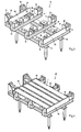
- the Fig. 1 shows a pallet 1 in a perspective view.
- the Euro-pallet 1 shown here is made exclusively of wooden parts and consists of five longitudinally extending cover boards 2a-2e, three transversely arranged transverse boards 3a-3c and three extending in the longitudinal direction floorboards 4a-4c. Each floorboard 4a is connected to the three transverse boards 3a-3c by means of three connecting blocks 5a-5c.
- the two inner cover boards 2b, 2d are narrower than the two outer and the middle cover board 2a, 2c, 2e.
- the individual parts of the pallets are connected to one another by means of connecting elements in the form of nails 6, wherein nails are hammered in both from the upper side and from the lower side.
- the nails 6 taken from the top connect the respective cover board 2a-2e to the underlying cross-board 3a-3c and the associated connection block, while the nails taken from the underside connect the respective floor board 4a-4c to the associated connection block. That is, a nail hammered from above penetrates both the respective deck and the transverse board and is anchored in the connection block, while a nail hammered from below penetrates the respective floorboard and is anchored in the corresponding connection block. The nails hammered in from below are not apparent from this illustration.
- the pallet longitudinal axis is designated L1.
- the Fig. 2 shows a pallet 1 in partially dismounted state.
- a skid which has been removed in a preceding step is missing, for example by severing the nails below the three transverse boards 3a, 3b, 3c.
- a separate skid to be replaced new skid 8 is shown separately.
- Fig. 3 shows a perspective view of the device 10, which is used for aligning and fixing of pallets and pallet parts.
- the device shown here is particularly suitable for aligning and fixing Euro wooden pallets and parts thereof.
- the device serves to precisely position and fix the pallet to be repaired and any parts to be newly attached, so that the new pallet parts can be fastened to the pallet by means of connecting elements -nails- and / or additional connecting elements can be attached to stabilize the pallet can.
- the device can also be used to align individual pallet parts, in particular floorboards and / or connecting blocks, positionally and to fix such that they by attaching new Fasteners can be fixed in the correct position on the pallet. This can be advantageous, for example, for repairing so-called lottery pallets.
- the device 10 shown in the initial state consists of a base frame which i.a. four feet, two side members 11, 13 and three cross members 15, 18, 21 has.
- the respective cross member 15, 18, 21 is formed substantially L-shaped, wherein the respective base part 16, 19, 22 extends in the vertical direction and forms a fixed transverse stop 17, 20, 23, to which create a pallet with its longitudinal side can.
- the actual transverse stop 17, 20, 23 is formed in each case by a rectangular plate.
- the tops of the cross member 15, 18, 21 at the same time form the bearing surfaces for the floorboards of a pallet, as will be explained below.
- a longitudinal stop 24 is fixedly arranged in the form of a strip which extends at a right angle to the aforementioned transverse stops 17, 20, 23. This longitudinal stop 24 forms a firm stop for the front side of the pallet.
- the foremost transverse stop 17 also forms a fixed reference point for the male pallet together with the longitudinal stop 24 mentioned.
- the two longitudinal members 11, 13 are also formed substantially L-shaped, wherein on the respective base part 12, 14 depending on a hydraulic cylinder 26, 27 is supported. At these two hydraulic cylinders 26, 27, a movable longitudinal stop 28 is attached in the form of another strip, by means of which the pallet can be pressed in the direction of the fixed longitudinal stop 24.
- the device comprises six further fixed transverse stops 37, 40, 43, 46, 49, 52.
- a total of nine fixed Transverse stops 17, 20, 23, 37, 40, 43, 46, 49, 52 are provided, whose position is matched to the total of nine connecting blocks of a pallet.
- Each of these nine fixed transverse stops 17, 20, 23, 37, 40, 43, 46, 49, 52 is a displaceable transverse stop 31, 33, 35, 38, 41, 44, 47, 50, 53 assigned, each by means of a hydraulic cylinder is displaceable.
- the device is particularly suitable for positionally accurate attachment of floorboards and / or connection blocks and / or runners, since the said parts are both clamped by the total of nine displaceable stops as well as positioned transversely to the longitudinal center axis.
- the device is also suitable to install cross boards and deck boards.
- a respective support plate 39, 42, 45, 48, 51 are arranged, on which the pallet can be supported with their cross boards.
- the support plate is not shown, but the provided for moving the transverse stop 53 hydraulic cylinder 54 can be seen.
- the respective hydraulic cylinder should be able to exert a force of at least 5 KN, in particular at least 15 KN in the direction of the associated stop, so that it can be ensured that any displaced and / or twisted pallet parts, in particular connecting blocks and / or floorboards, are pressed into their desired position can.
- the Fig. 4 shows the device 10 with a recorded therein pallet 1 in the active state.
- Active state means that the pallet 1 is clamped in the device by all movable stops by means of the associated printing cylinder in their Wirk ein procedure are.
- the pallet 1 by the three movable transverse stops 31, 33, 35 which presses the pallet 1 in the transverse direction against the three fixed transverse stops 17, 20, 23, together with the movable longitudinal stop 28, by means of which the pallet in the longitudinal direction against the longitudinal stop 24 is pressed, fixed along its circumference or aligned, so that it can be ensured that the outer dimensions of the pallet are within a predetermined nominal size.
- additional sensors may be provided if necessary.
- movable transverse stops are moved into their respective operative position.
- both the floorboards and the connecting blocks are aligned and fixed at least transversely to the pallet longitudinal axis positionally.
- the individual pallet parts can be fixed by attaching new fasteners in their desired position.
- the outer dimensions of the pallet are within a predetermined nominal size and all floor boards and connecting blocks aligned parallel to each other and positioned at least transversely to the pallet longitudinal axis position.
- defective floorboards are not replaced individually, but always in the form of runners, which has the advantage that the new fasteners can be mounted exclusively from the top of the pallet ago.
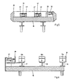
- Fig. 5 which the device according to Fig. 3 in a cross section extending through the central cross member 18, the three movable transverse stops 33, 47, 44 with the associated hydraulic pressure cylinders 32, 57, 58 and the three fixed transverse stops 46, 43, 20 can be seen in particular.
- the movable transverse stops 33, 47, 44 and the fixed transverse stops 46, 43, 20 are arranged in a row, so that in each case a movable transverse stop with a fixed transverse stop 33, 46; 47, 43; 44, 20 cooperates in pairs.
- the movable transverse stops 33, 47, 44 are shown in the retracted position of rest.
- the transverse stops 33, 47, 44 When the transverse stops 33, 47, 44 are in the rest position, a pallet be inserted into the device. If, for example, a floorboard or a runner are to be replaced, the floorboard or the runner is first inserted into the device at the intended position and then the partially dismantled pallet. Furthermore, it can be seen that the inner transverse stops 46, 47, 43, 44 are formed less high than the outer transverse stops 33, 20. In the present example, the inner transverse stops 46, 47, 43, 44 by at least the height of a cover and Cross boards of a pallet less trained than the outer transverse stops 33, 20. In addition, it can be seen that the respective hydraulic cylinder 57, 58 is supported with its back on a fixed transverse stop 46, 43.
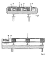
- Fig. 6 shows the device according to Fig. 3 in a longitudinal section running through the rear side member 13.
- the upper side 15a, 18a, 21a of the respective cross member 15, 18, 21 at the same time forms a support surface on which a pallet can be supported with its bottom boards.
- the fixed longitudinal stop 24 and by means of two hydraulic cylinders 27, 28 ( Fig. 3 ) movable longitudinal stop 28 can be seen.
- the Fig. 7 shows the device in a cross section according to Fig. 5 together with a pallet 1 received therein. Since the movable transverse stops 33, 47, 44 are in the retracted rest position -AusgangsSullivan-, exists between the respective transverse stop 33, 47, 44 and the corresponding pallet part in each case a gap S1, S2, S3.
- Fig. 8 shows a longitudinal section through the device located in the initial state with a recorded therein pallet. Between the front side of the pallet 1 and located in the rest position transverse stop 28 in turn there is a gap S4.
- Fig. 9 shows a cross section through the device in the active state with a recorded therein pallet.
- the two internal transverse transverse stops 47, 44 each press a bottom board 4b, 4a and a connecting block 5e, 5b against the associated fixed transverse stop 43, 20, while the outer movable transverse stop 33, the one floor board 4c, as well press the associated connection block 5f against the adjacent fixed transverse stop 46 and the one transverse board 3b against the outer fixed Transverse stop 20.
- the three connecting blocks 5b, 5e, 5f are fixed and positioned transversely to the longitudinal axis of the pallet together with the three floorboards 4a, 4b, 4c.
- Fig. 10 shows a longitudinal section through the device in the operative state with a pallet received therein.
- the movable longitudinal stop 28 presses both the respective floorboard 4b and the respective cover board 2c against the fixed longitudinal stop 24.
- the edge-side connecting blocks 5a, 5c and the two outer transverse boards 3a, 3c are loaded in such a way that they do not project outwards protrude.
- the device is suitable for repairing so-called Lotterpaletten in which no parts need to be replaced, but individual pallet parts may need to be repositioned and fixed in their desired position by attaching new fasteners.
- the movable stops are so matched to the fixed stops of the device that even at most moved and / or twisted pallet parts, especially floor boards and / or connecting blocks, are aligned correctly, so that they are fixed after the attachment of new fasteners in their desired position.
- the device 10 is associated with a fastening device by means of which the new connecting elements can be attached.
- a fastening device may for example consist of a simple, pneumatically operated, manually operated nail apparatus.
- a fully automatic attachment robot can be provided.
Landscapes
- Engineering & Computer Science (AREA)
- Life Sciences & Earth Sciences (AREA)
- Mechanical Engineering (AREA)
- Manufacturing & Machinery (AREA)
- Wood Science & Technology (AREA)
- Forests & Forestry (AREA)
- Pallets (AREA)
- Feeding Of Workpieces (AREA)
- Jigs For Machine Tools (AREA)
- Automatic Assembly (AREA)
Description
- Die vorliegende Erfindung bezieht sich auf eine Vorrichtung zum Ausrichten und/oder Fixieren von zu reparierenden Paletten und/oder Palettenteilen nach dem Oberbegriff des Anspruchs 1. Eine solche Vorrichtung ist aus der
WO 01/89781 - Aus der
DE-A-43 08 580 ist ein Verfahren sowie auf eine Vorrichtung zur Reparatur beschädigter Paletten bekannt. Die beschädigte Palette wird dazu in nach oben gekehrter Stellung auf einem Maschinentisch positioniert und fixiert. Danach werden die beschädigten Tragklötze und Latten mittels einer Trennvorrichtung herausgetrennt, welche in drei Koordinatenachsen verschiebbar gelagert ist. Die Trennvorrichtung weist einen Maschinenkopf auf, der mit einem senkrechten Antriebsschaft versehen ist, an dem endseitig ein rotierendes Kreissägeblatt angebracht ist. Der Durchmesser des Kreissägeblatts wird so gewählt, dass dieses kleiner ist als die lichte Weite zwischen den in Längsrichtung verlaufenden Reihen von Tragklötzen. Dadurch lässt sich das Kreissägeblatt zwischen die in Längsrichtung verlaufenden Reihen von Tragklötzen einbringen, so dass gezielt die beschädigten Teile der Palette herausgesägt werden können. Beim Heraustrennen der beschädigten Teile werden die Befestigungsmittel - Nägel- durchtrennt. Nachdem die beschädigten Teile herausgetrennt sind, wird die Palette einer Beschickungs- und Befestigungsstation zugeführt, wo die zu ersetzenden Teile an die entsprechende Stelle zugeführt und positioniert werden. Die eigentliche Befestigung der neuen Teile erfolgt mittels zwei Nageleinrichtungen, die gleichzeitig von oben und unten Nägel einschlagen. - Aus der
DE-A-198 22 229 ist ebenfalls ein Verfahren und eine Vorrichtung zur Reparatur beschädigter Paletten aus Holz bekannt. Hier werden in einem ersten Arbeitsschritt die beschädigten Bretter und/oder Kufen von der zu reparierenden Palette abgetrennt. In einem nächsten Arbeitsschritt werden die neuen Teile auf die Palette ausgerichtet und danach vernagelt. In einem weiteren Arbeitsschritt werden die Paletten gepresst, so dass allenfalls überstehende Nägel sowie nicht ganz anliegende Bretter angepresst werden. Die Vorrichtung zum Durchführen dieser Verfahrensschritte umfasst einen Zuförderer zum Zuführen der Paletten, einen Entstapler zum Vereinzeln der Paletten, eine Demontagestation zum selektiven Abtrennen der defekten Teile, eine Bestückungsstation zum Ersetzen der defekten Teile, eine Zentrier- und Nagelstation zum Befestigen der ersetzten Teile sowie eine Anpressstation zum Anpressen von überstehenden Nägeln sowie nicht ganz anliegenden Brettern. Die Zentrier- und Nagelstation dient u.a. dem exakten Positionieren der ersetzten Kufen bzw. Deckbretter. Dazu ist die Zentrier- und Nagelstation mit drei Zentrierkanälen zur Aufnahme der drei Kufen einer Palette versehen. Der rechte Zentrierkanal ist mit einer festen Aussenwand und einer mittels federbelasteten Stösseln beweglichen Innenwand versehen, während der mittlere Zentrierkanal zwei bewegliche Seitenwände aufweist, die über federbelastete Stössel nach innen gedrückt werden. Die Federkräfte der die beiden Seitenwände belastenden Stössel sind so ausgelegt, dass die mittlere Kufe relativ zur festen rechten Aussenwand positioniert wird. Schliesslich weist der linke Zentrierkanal je eine mittels federbelasteten Stösseln bewegliche Innen- und Aussenwand auf, welch letztere höher ist als die Palette. Dadurch soll erreicht werden, dass die gesamte Palette mitsamt ihrer linken Kufe auf die feste Aussenwand gedrückt und so positioniert wird. - Die Erfindung zielt darauf ab, eine Vorrichtung zum Ausrichten und/oder Fixieren von zu reparierenden Paletten und/oder Palettenteilen nach dem Oberbegriff des Anspruchs 1 derart weiterzubilden, dass die neu an der Palette anzubringende Palettenteile und/oder allenfalls verschobene und/oder verdrehte Palettenteile, insbesondere Bodenbretter und/oder Verbindungsklötze, lagegerecht ausgerichtet und fixiert werden, so dass sie durch das Anbringen von neuen Verbindungselementen schnell und einfach in ihrer Sollposition befestigt werden können.
- Zur Lösung dieser Aufgabe wird eine Vorrichtung bereitgestellt, welche die im Kennzeichen des Anspruchs 1 angeführten Merkmale aufweist.
- Vorzugsweise wird durch die Vorrichtung gemäss Anspruch 4 sichergestellt, dass die Aussenmasse der Palette innerhalb eines vorgegebenen Nennmasses liegen.
- Weitere bevorzugte Ausführungsformen der Vorrichtung sind in den abhängigen Ansprüchen 2, 3 und 5 bis 10 umschrieben.
- Ein bevorzugtes Ausführungsbeispiel der erfindungsgemässen Vorrichtung wird nachfolgend unter Bezugnahme auf die beiliegenden Zeichnungen näher erläutert. Dabei zeigt:
- Fig. 1
- eine Palette 1 in einer perspektivischen Ansicht;
- Fig. 2
- eine teildemontierte Palette zusammen mit einer neuen Kufe;
- Fig. 3
- eine perspektivische Ansicht der Vorrichtung zum Ausrichten und Fixieren von zu reparierenden Paletten und Palettenteilen;
- Fig. 4
- die Vorrichtung gemäss
Fig. 3 in einer perspektivischen Ansicht zusammen mit einer darin aufgenommenen Palette; - Fig. 5
- einen Querschnitt durch die Vorrichtung gemäss
Fig.3 ; - Fig. 6
- einen Längsschnitt durch die Vorrichtung gemäss
Fig.3 ; - Fig. 7
- einen Querschnitt durch die sich im Ausgangszustand befindliche Vorrichtung mit einer darin aufgenommene Palette;
- Fig.8
- einen Längsschnitt durch die sich im Ausgangszustand befindliche Vorrichtung mit einer darin aufgenommene Palette;
- Fig. 9
- einen Querschnitt durch die sich im Wirkzustand befindliche Vorrichtung mit einer darin aufgenommene Palette, und
- Fig. 10
- einen Längsschnitt durch die sich im Wirkzustand befindliche Vorrichtung mit einer darin aufgenommene Palette.
- Die
Fig. 1 zeigt eine Palette 1 in einer perspektivischen Ansicht. Die hier dargestellte Euro-Palette 1 ist ausschliesslich aus Holzteilen gefertigt und besteht aus fünf in Längsrichtung verlaufenden Deckbrettern 2a-2e, drei darunter quer angeordneten Querbrettern 3a-3c sowie drei in Längsrichtung verlaufenden Bodenbrettern 4a-4c. Jedes Bodenbrett 4a ist mittels drei Verbindungsklötzen 5a-5c mit den drei Querbrettern 3a-3c verbunden. Von den fünf Deckbrettern sind die beiden innen liegenden Deckbretter 2b, 2d schmaler ausgebildet als die beiden äusseren und das mittlere Deckbrett 2a, 2c, 2e. Die einzelnen Paletten-Teile sind mittels Verbindungselementen in Form von Nägeln 6 miteinander verbunden, wobei sowohl von der Oberseite wir auch von der Unterseite her Nägel eingeschlagen sind. Die von der Oberseite eingeschlagenen Nägel 6 verbinden das jeweilige Deckbrett 2a-2e mit dem darunter liegenden Querbrett 3a-3c sowie dem zugehörigen Verbindungsklotz, während die von der Unterseite eingeschlagenen Nägel das jeweilige Bodenbrett 4a-4c mit dem zugehörigen Verbindungsklotz verbinden. D.h. ein von oben eingeschlagener Nagel durchdringt sowohl das jeweilige Deck- wie auch das Querbrett und ist im Verbindungsklotz verankert, während ein von unten eingeschlagener Nagel das jeweilige Bodenbrett durchdringt und im entsprechenden Verbindungsklotz verankert ist. Die von unten eingeschlagenen Nägel sind aus dieser Darstellung nicht ersichtlich. Die Palettenlängsachse ist mit L1 bezeichnet. - Die
Fig. 2 zeigt eine Palette 1 in teildemontiertem Zustand. Namentlich fehlt eine Kufe, welche in einem vorangehenden Schritt entfernt wurde, beispielsweise durch Durchtrennen der Nägel unterhalb der drei Querbretter 3a, 3b, 3c. Eine die abgetrennte Kufe zu ersetzende neue Kufe 8 ist separat dargestellt. -
Fig. 3 zeigt eine perspektivische Ansicht der Vorrichtung 10, welche dem Ausrichten und Fixieren von Paletten und Palettenteilen dient. Die hier gezeigte Vorrichtung eignet sich insbesondere zum Ausrichten und Fixieren von Euro-Holzpaletten sowie Teilen davon. Die Vorrichtung dient einerseits dazu, die zu reparierende Palette sowie die ggf. neu daran anzubringenden Teile positionsgenau auszurichten und zu Fixieren, damit die neuen Palettenteile mittels Verbindungselementen -Nägeln- an der Palette befestigt werden können und/oder zusätzliche Verbindungselemente zum Stabilisieren der Palette angebracht werden können. Die Vorrichtung kann aber auch dazu verwendet werden, um einzelne Palettenteile, insbesondere Bodenbretter und/oder Verbindungsklötze, lagegerecht auszurichten und derart zu fixieren, dass sie durch das Anbringen von neuen Verbindungselementen in der korrekten Position an der Palette fixiert werden können. Dies kann beispielsweise zum Reparieren von sogenannten Lotterpaletten vorteilhaft sein. - Die im Ausgangszustand dargestellte Vorrichtung 10 besteht aus einem Grundgestell, das u.a. vier Füsse, zwei Längsträger 11, 13 sowie drei Querträger 15, 18, 21 aufweist. Der jeweilige Querträger 15, 18, 21 ist im wesentlichen L-förmig ausgebildet, wobei sich der jeweilige Basisteil 16, 19, 22 in vertikaler Richtung erstreckt und einen festen Queranschlag 17, 20, 23 bildet, an welchem sich eine Palette mit ihrer Längsseite anlegen kann. Der eigentliche Queranschlag 17, 20, 23 wird jeweils durch eine rechteckige Platte gebildet. Die Oberseiten der Querträger 15, 18, 21 bilden zugleich die Auflageflächen für die Bodenbretter einer Palette, wie nachfolgend noch erläutert wird. An dem vordersten Querträger 15 ist ein Längsanschlag 24 in Form einer Leiste fest angeordnet, welche unter einem rechten Winkel zu den vorgängig genannten Queranschlägen 17, 20, 23 verläuft. Dieser Längsanschlag 24 bildet einen festen Anschlag für die Stirnseite der Palette. Der vorderste Queranschlag 17 bildet zusammen mit dem genannten Längsanschlag 24 zudem einen festen Referenzpunkt für die aufzunehmende Palette.
- Die beiden Längsträger 11, 13 sind ebenfalls im wesentlichen L-förmig ausgebildet, wobei an dem jeweiligen Basisteil 12, 14 je ein Hydraulikzylinder 26, 27 abgestützt ist. An diesen beiden Hydraulikzylindern 26, 27 ist ein beweglicher Längsanschlag 28 in Form einer weiteren Leiste befestigt, mittels welchem die Palette in Richtung des festen Längsanschlags 24 gedrückt werden kann.
- An dem dem festen Queranschlag 17, 20, 23 gegenüberliegenden Ende des jeweiligen Querträgers 15, 18, 21 ist jeweils ein über einen Hydraulikzylinder 30, 32, 34 betätigbarer, beweglicher Queranschlag 31, 33, 35 angeordnet, der auch in diesem Fall durch eine rechteckige Platte gebildet wird. Somit begrenzen die genannten drei festen Queranschläge 17, 20, 23 zusammen mit den drei beweglichen Queranschlägen 31, 33, 35 und dem festen sowie dem beweglichen Längsanschlag 24, 28 eine rechteckigen Aussparung zur Aufnahme einer Palette.
- Neben den drei genannten festen Queranschlägen 17, 20, 23 am Ende des jeweiligen Querträgers 15, 18, 21 umfasst die Vorrichtung noch sechs weitere feststehende Queranschläge 37, 40, 43, 46, 49, 52. Somit sind insgesamt neun feststehende Queranschläge 17, 20, 23, 37, 40, 43, 46, 49, 52 vorgesehen, deren Position auf die insgesamt neun Verbindungsklötze einer Palette abgestimmt ist. Jedem dieser neun feststehenden Queranschläge 17, 20, 23, 37, 40, 43, 46, 49, 52 ist ein verschiebbarer Queranschlag 31, 33, 35, 38, 41, 44, 47, 50, 53 zugeordnet, der jeweils mittels eines Hydraulikzylinders verschiebbar ist. Durch die paarweise Anordnung eines festen mit einem beweglichen Queranschlags soll sichergestellt werden, dass sowohl die drei Bodenbretter wie auch die neun Verbindungsklötze einer Palette parallel zueinander ausgerichtet und fixiert werden können. Da zudem jedes Bodenbrett wie auch die drei zugehörigen Verbindungsklötze gegen einen festen Queranschlag 17, 20, 23, 37, 40, 43, 46, 49, 52 gedrückt werden können, werden die drei Bodenbretter und die neun Verbindungsklötze nicht nur parallel zueinander ausgerichtet, sondern deren Position quer zur Längsmittelachse der Palette wird auch absolut festgelegt. Dadurch eignet sich die Vorrichtung einerseits zum Reparieren von sogenannten Lotterpaletten, bei denen die Position der Bodenbretter wie auch der Verbindungsklötze überprüft bzw. festgelegt oder korrigiert werden muss. Andererseits eignet sich die Vorrichtung insbesondere auch zum positionsgenauen Anbringen von Bodenbrettern und/oder Verbindungsklötzen und/oder Kufen, da die genannten Teile durch die insgesamt neun verschiebbaren Anschläge sowohl festgeklemmt wie auch quer zur Längsmittelachse positioniert werden. Natürlich eignet sich die Vorrichtung auch um Querbretter und Deckbretter anzubringen.
- Über den sechs innerhalb der Aussparung angeordneten Hydraulikzylindern zum Verschieben der beweglichen Queranschläge 38, 41, 44, 47, 50, 53 ist je eine Stützplatte 39, 42, 45, 48, 51 angeordnet, auf welcher sich die Palette mit ihren Querbrettern abstützen kann. Bei dem in Blickrichtung gesehen hintersten Queranschlag 53 ist die Stützplatte nicht eingezeichnet, dafür ist der zum Verschieben des Queranschlags 53 vorgesehene Hydraulikzylinder 54 ersichtlich. Der jeweilige Hydraulikzylinder soll eine Kraft von zumindest 5 KN, insbesondere zumindest 15 KN in Richtung des zugeordneten Anschlags ausüben können, damit sichergestellt werden kann, dass ggf. verschobene und/oder verdrehte Palettenteile, insbesondere Verbindungsklötze und/oder Bodenbretter, in ihre Sollposition gedrückt werden können.
- Die
Fig. 4 zeigt die Vorrichtung 10 mit einer darin aufgenommenen Palette 1 im Wirkzustand. Wirkzustand bedeutet, dass die Palette 1 in der Vorrichtung eingespannt ist, indem sämtliche verschiebbaren Anschläge mittels des zugehörigen Druckzylinders in ihre Wirkstellung verfahren sind. Wie ersichtlich, wird die Palette 1 durch die drei beweglichen Queranschläge 31, 33, 35, welche die Palette 1 in Querrichtung gegen die drei festen Queranschläge 17, 20, 23 drückt, zusammen mit dem beweglichen Längsanschlag 28, mittels welchem die Palette in Längsrichtung gegen den Längsanschlag 24 gedrückt wird, entlang ihres Umfanges fixiert bzw. ausgerichtet, so dass sichergestellt werden kann, dass die Aussenmasse der Palette innerhalb eines vorgegebenen Nennmasses liegen. Zur Überwachung der Aussenmasse der Palette können ggf. zusätzliche Sensoren vorgesehen werden. Natürlich sind im Wirkzustand auch die übrigen, aus dieser Darstellung nicht ersichtlichen beweglichen Queranschläge in ihre jeweilige Wirkposition verschoben. Zudem wird durch das Zusammenwirken der beweglichen mit den festen Queranschlägen sichergestellt, dass sowohl die Bodenbretter wie auch die Verbindungsklötze zumindest quer zur Palettenlängsachse lagegerecht ausgerichtet und fixiert sind. In dem eingespannten Zustand der Palette können die einzelnen Palettenteile durch das Anbringen von neuen Verbindungselementen in ihrer Sollposition fixiert werden. - Somit kann durch die Vorrichtung im Zusammenhang mit dem Anbringen von neuen Verbindungselementen bewirkt werden, dass die Aussenmasse der Palette innerhalb eines vorgegebenen Nennmasses liegen und sämtliche Bodenbretter wie auch Verbindungsklötze parallel zueinander ausgerichtet und zumindest quer zu der Palettenlängsachse lagegerecht positioniert sind.
- Vorzugsweise werden defekte Bodenbretter nicht einzeln ersetzt, sondern immer in der Form von Kufen, was den Vorteil hat, dass die neuen Verbindungselemente ausschliesslich von der Oberseite der Palette her angebracht werden können.
- Aus der
Fig. 5 , welche die Vorrichtung gemässFig. 3 in einem durch den mittleren Querträger 18 verlaufenden Querschnitt zeigt, sind insbesondere die drei beweglichen Queranschläge 33, 47, 44 mit den zugehörigen hydraulischen Druckzylindern 32, 57, 58 sowie die drei feststehenden Queranschläge 46, 43, 20 ersichtlich. Die beweglichen Queranschläge 33, 47, 44 sowie die feststehenden Queranschläge 46, 43, 20 sind in einer Reihe angeordnet, so dass jeweils ein beweglicher Queranschlag mit einem feststehenden Queranschlag 33, 46; 47, 43; 44, 20 paarweise zusammenwirkt. In dieser Darstellung sind die beweglichen Queranschläge 33, 47, 44 in der zurückgezogenen Ruhestellung gezeigt. Wenn sich die Queranschläge 33, 47, 44 in der Ruhestellung befinden, kann eine Palette in die Vorrichtung eingelegt werden. Soll beispielsweise ein Bodenbrett oder eine Kufe ersetzt werden, so wird zuerst das Bodenbrett bzw. die Kufe an der vorgesehenen Position in die Vorrichtung eingesetzt und danach die teildemontierte Palette. Im weiteren ist ersichtlich, dass die inneren Queranschläge 46, 47, 43, 44 weniger hoch ausgebildet sind als die äusseren Queranschläge 33, 20. Im vorliegenden Beispiel sind die inneren Queranschläge 46, 47, 43, 44 um zumindest die Höhe eines Deck- und Querbretts einer Palette weniger hoch ausgebildet als die äusseren Queranschläge 33, 20. Zudem ist erkennbar, dass sich der jeweilige Hydraulikzylinder 57, 58 mit seiner Rückseite an einem feststehenden Queranschlag 46, 43 abstützt. -
Fig. 6 zeigt die Vorrichtung gemässFig. 3 in einem durch den hinteren Längsträger 13 verlaufenden Längsschnitt. In dieser Darstellung ist erkennbar, dass die Oberseite 15a, 18a, 21 a des jeweiligen Querträgers 15, 18, 21 zugleich eine Auflagefläche bildet, auf welcher sich eine Palette mit ihren Bodenbrettern abstützen kann. Im weiteren sind der feststehende Längsanschlag 24 sowie der mittels zwei Hydraulikzylindern 27, 28 (Fig. 3 ) bewegliche Längsanschlag 28 ersichtlich. - Die
Fig. 7 zeigt die Vorrichtung in einem Querschnitt gemässFig. 5 zusammen mit einer darin aufgenommenen Palette 1. Da sich die beweglichen Queranschläge 33, 47, 44 in der zurückgezogenen Ruhestellung -Ausgangszustand- befinden, besteht zwischen dem jeweiligen Queranschlag 33, 47, 44 und dem entsprechenden Palettenteil jeweils ein Spalt S1, S2, S3. -
Fig. 8 zeigt einen Längsschnitt durch die sich im Ausgangszustand befindliche Vorrichtung mit einer darin aufgenommene Palette. Zwischen der Stirnseite der Palette 1 und dem sich in der Ruhestellung befindlichen Queranschlag 28 besteht wiederum ein Spalt S4. -
Fig. 9 zeigt einen Querschnitt durch die sich im Wirkzustand befindliche Vorrichtung mit einer darin aufgenommene Palette. In dieser Darstellung ist erkennbar, dass die beiden innen liegenden beweglichen Queranschläge 47, 44 jeweils ein Bodenbrett 4b, 4a sowie einen Verbindungsklotz 5e, 5b gegen den zugehörigen festen Queranschlag 43, 20 drücken, während der äussere bewegliche Queranschlag 33 das eine Bodenbrett 4c, sowie den zugehörigen Verbindungsklotz 5f gegen den benachbarten festen Queranschlag 46 drückt sowie das eine Querbrett 3b gegen den äusseren festen Queranschlag 20. Dadurch werden die drei Verbindungsklötze 5b, 5e, 5f zusammen mit den drei Bodenbrettern 4a, 4b, 4c quer zur Palettenlängsachse fixiert und positioniert. -
Fig. 10 zeigt einen Längsschnitt durch die sich im Wirkzustand befindliche Vorrichtung mit einer darin aufgenommene Palette. Wie ersichtlich drückt der bewegliche Längsanschlag 28 sowohl das jeweilige Bodenbrett 4b wie auch das jeweilige Deckbrett 2c gegen den festen Längsanschlag 24. Zudem werden auch die randseitigen Verbindungsklötze 5a, 5c sowie die beiden aussen liegenden Querbretter 3a, 3c derart belastet, dass sie nicht nach aussen vorstehen. - Zusammenfassend kann festgehalten werden, dass sich defekte Paletten mit Hilfe dieser Vorrichtung einfach und schnell reparieren lassen, indem mit Hilfe der Vorrichtung die zu ersetzenden Palettenteile gegenüber der teildemontierten Palette ausgerichtet und fixiert werden können. Zudem wird sichergestellt, dass die für einen einwandfreien Zustand der Palette wesentlichen Palettenteile, namentlich die Bodenbretter sowie die Verbindungsklötze, mit Hilfe der Vorrichtung lagegerecht ausgerichtet und fixiert werden, so dass die genannten Palettenteile durch das Anbringen von neuen Verbindungselementen in der Sollposition festgenagelt bzw. mit den zugeordneten Palettenteilen verbunden werden können.
- Ebenso eignet sich die Vorrichtung zur Reparatur sogenannter Lotterpaletten, bei denen keine Teile ersetzt werden müssen, sondern einzelne Palettenteile ggf. neu positioniert und in ihrer Solllage durch Anbringen neuer Verbindungselemente fixiert werden müssen. Jedenfalls sind die beweglichen Anschläge derart auf die festen Anschläge der Vorrichtung abgestimmt, dass auch allenfalls verschobene und/oder verdrehte Palettenteile, insbesondere Bodenbretter und/oder Verbindungsklötze, lagegerecht ausgerichtet werden, so dass sie nach dem Anbringen von neuen Verbindungselementen in ihrer Sollposition fixiert sind.
- Vorzugsweise ist der Vorrichtung 10 eine Befestigungsvorrichtung zugeordnet, mittels welcher die neuen Verbindungselemente angebracht werden können. Eine solche Befestigungsvorrichtung kann beispielsweise aus einem einfachen, pneumatisch betriebenen, manuell zu betätigenden Nagelapparat bestehen. Ebenso kann natürlich ein vollautomatischer Befestigungsroboter vorgesehen werden.
-
- 1.
- Palette
- 2.
- Deckbretter
- 3.
- Querbretter
- 4.
- Bodenbretter
- 5.
- Verbindungsklötze
- 6.
- Nägel
- 7.
- 8.
- 9.
- 10.
- Vorrichtung
- 11.
- vorderer Längsträger
- 12.
- 12. Basisteil
- 13.
- hinterer Längsträger
- 14.
- Basisteil
- 15.
- vorderer Querträger
- 16.
- Basisteil
- 17.
- fester Queranschlag
- 18.
- mittlerer Querträger
- 19.
- Basisteil
- 20.
- fester Queranschlag
- 21.
- hinterer Querträger
- 22.
- Basisteil
- 23.
- fester Queranschlag
- 24.
- fester Längsanschlag
- 25.
- 26.
- Hydraulikzylinder
- 27.
- Hydraulikzylinder
- 28.
- beweglicher Längsanschlag
- 29.
- 30.
- Hydraulikzylinder
- 31.
- beweglicher Queranschlag
- 32.
- Hydraulikzylinder
- 33.
- beweglicher Queranschlag
- 34.
- Hydraulikzylinder
- 35.
- beweglicher Queranschlag
- 36.
- 37.
- fester Queranschlag
- 38.
- beweglicher Queranschlag
- 39.
- Abstützplatte
- 40.
- fester Queranschlag
- 41.
- beweglicher Queranschlag
- 42.
- Abstützplatte
- 43.
- fester Queranschlag
- 44.
- beweglicher Queranschlag
- 45.
- Abstützplatte
- 46.
- fester Queranschlag
- 47.
- beweglicher Queranschlag
- 48.
- Abstützplatte
- 49.
- fester Queranschlag
- 50.
- beweglicher Queranschlag
- 51.
- Abstützplatte
- 52.
- fester Queranschlag
- 53.
- beweglicher Queranschlag
- 54.
- Hydraulikzylinder
- 55.
- 55.
- 56.
- 57.
- 58.
- 59.
- 60.
- 61.
- 62.
- 63.
- 64.
- 65.
- 66.
- 67.
- 68.
- 69.
- 70.
Claims (10)
- Vorrichtung (10) zum Ausrichten und/oder Fixieren von zu reparierende Paletten (1) und/oder Palettenteilen (8), wobei die Paletten (1) eine Mehrzahl von Deckbrettern (2a-2e), Querbrettern (3a-3c) und Bodenbrettern (4a-4c) umfassen und das jeweilige Bodenbrett (4a) mittels Verbindungsklötzen (5a-5c) mit den Querbrettern (3a-3c) verbunden ist, und wobei die genannten Palettenteile mittels Verbindungselementen (6), insbesondere Nägeln, zusammengehalten werden und die Vorrichtung (10) zumindest einen festen Queranschlag (17, 20, 23, 37, 40, 43, 46, 49, 52) und einen beweglichen Queranschlag (38, 44, 50, 41, 47, 53, 31, 33, 35) für jedes Bodenbrett und/oder jeden Verbindungsklotz aufweist, und wobei der bewegliche Queranschlag (38, 44, 50, 41, 47, 53, 31, 33, 35) das jeweilige Bodenbrett und/oder den jeweiligen Verbindungsklotz derart gegen den zugehörigen festen Queranschlag (17, 20, 23, 37, 40, 43, 46, 49, 52) zu drücken bestimmt ist, dass das jeweilige Bodenbrett bzw. der jeweilige Verbindungsklotz zumindest quer zur Palettenlängsachse (L1) positioniert und auch fixiert ist/sind, dadurch gekennzeichnet, dass die Vorrichtung (10) einen durch zwei feste Anschläge (17, 24) definierten Referenzpunkt für die Palette (1) aufweist, wobei die beiden den Referenzpunkt definierenden Anschläge (17, 24) um 90° zueinander versetzt sind und wobei den beiden den Referenzpunkt bildenden Anschlägen (17, 24) zumindest je ein beweglicher Längsanschlag (28) bzw. Querschlag (31) zugeordnet ist, mittels welchen die Palette entlang ihrer Aussenseiten gegen die den Referenzpunkt bildenden Anschläge (17, 24) drückbar ist.
- Vorrichtung (10) nach Anspruch 1, dadurch gekennzeichnet, dass jedem festen Queranschlag (17, 20, 23, 37, 40, 43, 46, 49, 52) ein beweglicher Queranschlag (38, 44, 50, 41, 47, 53, 31, 33, 35) zugeordnet ist.
- Vorrichtung (10) nach Anspruch 1 oder 2, dadurch gekennzeichnet, dass die Vorrichtung (10) für jeden Verbindungsklotz einen festen Queranschlag (17, 20, 23, 37, 40, 43, 46, 49, 52) und einen beweglichen Queranschlag (38, 44, 50, 41, 47, 53, 31, 33, 35) aufweist, wobei die Anschläge paarweise derart zusammenwirken, dass sie sowohl die Verbindungsklötze wie auch die Bodenbretter zumindest quer zur Palettenlängsachse (L1) positionieren und auch fixieren.
- Vorrichtung (10) nach einem der vorhergehenden Ansprüche, dadurch gekennzeichnet, dass die Vorrichtung (10) zusätzlich zumindest einen festen Längsanschlag (24) und zumindest einen beweglichen Längsanschlag (28) aufweist, welche unter einem rechten Winkel zu den vorgängig genannten Queranschlägen angeordnet sind und insbesondere dazu bestimmt sind, die Masshaltigkeit der Palette in Längsrichtung zu definieren und/oder die Deckbretter und/oder die Bodenbretter in Richtung der Palettenlängsachse (L1) zu positionieren und fixieren.
- Vorrichtung (10) nach einem der vorhergehenden Ansprüche, zum Fixieren und/oder Positionieren von Euro-Paletten, welche drei Bodenbretter sowie neun Verbindungsklötze aufweisen, dadurch gekennzeichnet, dass die Vorrichtung (10) neun feste Queranschläge (17, 20, 23, 37, 40, 43, 46, 49, 52) sowie neun bewegliche Queranschläge (38, 44, 50, 41, 47, 53, 31, 33, 35) aufweist, wobei die beweglichen Queranschläge (38, 44, 50, 41, 47, 53, 31, 33, 35) das jeweilige Bodenbrett und/oder die zugeordneten Verbindungsklötze und/oder die Querbretter derart gegen einen festen Anschlag zu drücken bestimmt sind, dass das jeweilige Bodenbrett und/oder die Verbindungsklötze und/oder die Querbretter quer zur Palettenlängsachse positioniert und auch fixiert ist/sind.
- Vorrichtung (10) nach einem der vorhergehenden Ansprüche, dadurch gekennzeichnet, dass die Vorrichtung (10) eine rechteckige Aussparung zur Aufnahme der Palette aufweist, deren eine Längsseite durch zumindest einen festen Queranschlag (17, 20, 23) gebildet ist, während die andere Längsseite durch zumindest einen beweglichen Queranschlag (31, 33, 35) gebildet ist.
- Vorrichtung (10) nach Anspruch 4 und 6, dadurch gekennzeichnet, dass die beiden Stirnseiten der Aussparung durch den zumindest einen festen Längsanschlag (24) und den zumindest einen beweglichen Längsanschlag (28) gebildet sind.
- Vorrichtung (10) nach Anspruch 6 oder 7, dadurch gekennzeichnet, dass innerhalb der Aussparung zusätzliche feste Queranschläge (37, 40, 43, 46, 49, 52) sowie zusätzliche bewegliche Queranschläge (38, 41, 44, 47, 50, 53) angeordnet sind, welche niedriger sind als die die Aussparung begrenzenden äusseren Anschläge (17, 20, 23, 31, 33, 35, 24, 28).
- Vorrichtung (10) nach Anspruch 4 und 6, dadurch gekennzeichnet, dass die eine Längsseite der Aussparung durch drei feste Queranschläge (17, 20, 23) gebildet ist, während die andere Längsseite der Aussparung durch drei bewegliche Queranschläge (31, 33, 35) gebildet ist, und dass die eine Stirnseite der Aussparung durch einen festen Längsanschlag (24) gebildet ist, während die andere Stirnseite durch einen beweglichen Längsanschlag (28) gebildet ist.
- Vorrichtung (10) nach einem der vorhergehenden Ansprüche, dadurch gekennzeichnet, dass die beweglichen Anschläge (28, 31, 33, 35, 47, 44) mit zumindest je einem hydraulisch, pneumatisch oder elektromechanisch betätigbaren Druckzylinder (26, 27 30, 32, 34, 57, 58) verbunden sind, welche in Richtung des jeweils zugeordneten festen Anschlags (24, 40, 46, 52, 43, 20) eine Kraft von zumindest 5 KN, insbesondere zumindest 15 KN, auszuüben bestimmt sind.
Priority Applications (2)
| Application Number | Priority Date | Filing Date | Title |
|---|---|---|---|
| PL06405475T PL1785221T3 (pl) | 2005-11-14 | 2006-11-10 | Urządzenie do ustawiania i/lub ustalania naprawianych palet i/lub części palet |
| SI200630665T SI1785221T1 (sl) | 2005-11-14 | 2006-11-10 | Naprava za poravnavanje in/ali fiksiranje palet in/ali delov palet, ki jih je treba popraviti |
Applications Claiming Priority (1)
| Application Number | Priority Date | Filing Date | Title |
|---|---|---|---|
| CH18182005 | 2005-11-14 |
Publications (2)
| Publication Number | Publication Date |
|---|---|
| EP1785221A1 EP1785221A1 (de) | 2007-05-16 |
| EP1785221B1 true EP1785221B1 (de) | 2010-02-24 |
Family
ID=37596288
Family Applications (2)
| Application Number | Title | Priority Date | Filing Date |
|---|---|---|---|
| EP06405472A Active EP1785220B1 (de) | 2005-11-14 | 2006-11-07 | Verfahren und Vorrichtung zur Reparatur beschädigter Paletten |
| EP06405475A Active EP1785221B1 (de) | 2005-11-14 | 2006-11-10 | Vorrichtung zum Ausrichten und/oder Fixieren von zu reparierenden Paletten und/oder Palettenteilen |
Family Applications Before (1)
| Application Number | Title | Priority Date | Filing Date |
|---|---|---|---|
| EP06405472A Active EP1785220B1 (de) | 2005-11-14 | 2006-11-07 | Verfahren und Vorrichtung zur Reparatur beschädigter Paletten |
Country Status (17)
| Country | Link |
|---|---|
| US (2) | US7815177B2 (de) |
| EP (2) | EP1785220B1 (de) |
| JP (2) | JP5129474B2 (de) |
| KR (2) | KR101275383B1 (de) |
| CN (2) | CN1974153B (de) |
| AT (2) | ATE440694T1 (de) |
| CA (2) | CA2567924C (de) |
| DE (2) | DE502006004647D1 (de) |
| ES (2) | ES2331152T3 (de) |
| HR (2) | HRP20090574T1 (de) |
| MX (2) | MXPA06013183A (de) |
| NO (2) | NO338339B1 (de) |
| PL (2) | PL1785220T3 (de) |
| RU (2) | RU2359820C2 (de) |
| SI (2) | SI1785220T1 (de) |
| TW (2) | TWI371333B (de) |
| UA (2) | UA89782C2 (de) |
Families Citing this family (58)
| Publication number | Priority date | Publication date | Assignee | Title |
|---|---|---|---|---|
| DK2078954T3 (en) * | 2002-12-10 | 2017-08-07 | Chep Technology Pty Ltd | Automated pallet inspection |
| PL1694570T3 (pl) | 2003-12-19 | 2011-10-31 | Chep Technology Pty Ltd | Urządzenie oraz sposób automatycznej kontroli i naprawy palety |
| ES2264640B1 (es) * | 2005-06-17 | 2007-12-01 | Ferraplana, S.L. | Equipo automatico para la fabricacion de armaduras metalicas. |
| TWI371333B (en) * | 2005-11-14 | 2012-09-01 | Holliger Paletten Logistik Ag | Method and apparatus for repairing damaged pallets |
| CN101470465A (zh) * | 2007-12-27 | 2009-07-01 | 鸿富锦精密工业(深圳)有限公司 | 铰链定位治具 |
| US8266790B2 (en) | 2008-01-25 | 2012-09-18 | Chep Technology Pty. Limited | Board removal apparatus for a pallet |
| AU2008200441B8 (en) * | 2008-01-29 | 2011-04-21 | Chep Technology Pty Limited | Lead board adjustment apparatus for a pallet and associated methods |
| DE102008019589A1 (de) * | 2008-04-18 | 2009-10-22 | Gressel Ag | Mehrfachspanner |
| DE102008048383A1 (de) * | 2008-09-22 | 2010-03-25 | Baumer Inspection Gmbh | Automatisches Flicken von Holzpaneelen mit ästhetischer Rekonstruktion |
| US7896211B2 (en) * | 2009-01-13 | 2011-03-01 | Wen-Yi Tu | Nailing mechanism for a packing plates |
| NL2003646C2 (nl) * | 2009-10-15 | 2011-04-18 | Douna Engineering B V | Pallet-reparatie inrichting en werkwijze voor het repareren van een pallet. |
| SE1051215A1 (sv) | 2010-11-19 | 2011-09-06 | Yaskawa Nordic Ab | Anordning för demontering av valda delar av sammanfogade lastpallar |
| KR101327288B1 (ko) | 2011-08-31 | 2013-11-11 | 주식회사 경주수출포장 | 목재 파렛트의 조립장치 |
| CN102310306A (zh) * | 2011-09-27 | 2012-01-11 | 江苏银河电子股份有限公司 | 快速修复用于冲压密集孔凹模的方法 |
| SE536443C2 (sv) * | 2012-03-16 | 2013-11-05 | Anordning och metod för reparation av en lastpall | |
| CN102717416B (zh) * | 2012-06-06 | 2015-01-21 | 缙云县欣宇金属制品有限公司 | 一种木托盘底座的生产流水线 |
| WO2014022470A1 (en) * | 2012-07-31 | 2014-02-06 | CLM Pallet Recycling, Inc. | Pallet refurbishing apparatus and method |
| FR2994701B1 (fr) * | 2012-08-23 | 2014-09-26 | Bernard Eugene Marie Choquet | Mecanisme de reglage d'intervalles et/ou d'angle pour realiser une structure d'escalier ou d'etagement |
| US20140076954A1 (en) * | 2012-09-18 | 2014-03-20 | Stanley Fastening Systems, L.P. | Pallet nail clinching apparatus and methods |
| DE202013006761U1 (de) * | 2013-07-26 | 2013-08-29 | Gerd Rebmann | Oberflächenabtaster zur Erkennung von überstehenden Stahlnägeln in Einweg- oder Mehrwegpaletten. |
| DE102013218391A1 (de) * | 2013-09-13 | 2015-03-19 | Krones Ag | Vorrichtung und Verfahren zum Bewegen von Transportelementen in einer Behälterbehandlungsanlage |
| DE102015000196A1 (de) * | 2015-01-15 | 2016-07-21 | Böllhoff Verbindungstechnik GmbH | Schallreduktionsvorrichtung sowie ein Fügeverfahren und ein Bauteilbearbeitungsverfahren mit Schalldämmung |
| US9994299B2 (en) * | 2015-04-03 | 2018-06-12 | The Boeing Company | Tool and method of installing a bulkhead within a structure |
| CN104972541A (zh) * | 2015-05-06 | 2015-10-14 | 太仓顺风木业制品有限公司 | 一种模具及其使用方法 |
| CN106542281B (zh) * | 2015-09-21 | 2018-12-28 | 苏州科维新型包装有限公司 | 板条上料装置 |
| US9809351B1 (en) | 2017-01-18 | 2017-11-07 | Victor Oliver | Method and apparatus for constructing pallets |
| US10486328B2 (en) * | 2017-01-31 | 2019-11-26 | Palletec, Llc | Methods and systems for fastening bed foundations |
| CN108481229A (zh) * | 2017-02-18 | 2018-09-04 | 薛峰 | 一种文物古玩修复用夹持装置 |
| CN107486693B (zh) * | 2017-06-30 | 2019-06-21 | 东莞华贝电子科技有限公司 | 压机系统及其控制方法 |
| US10252867B2 (en) * | 2017-07-21 | 2019-04-09 | Chep Technology Pty Limited | Pallet positioning station and associated methods |
| CN107695668A (zh) * | 2017-10-31 | 2018-02-16 | 惠州市昇沪汽车紧固件科技有限公司 | 一种用于全自动穿垫机的螺丝固定板导正装置 |
| RU184234U1 (ru) * | 2017-11-17 | 2018-10-18 | Евгений Юрьевич Чирков | Механизм фиксации материала в заданном размере |
| JP7044326B2 (ja) * | 2018-04-11 | 2022-03-30 | 国立大学法人千葉大学 | 多軸ロボットの固定装置および加工システム |
| CN108858636B (zh) * | 2018-07-06 | 2020-12-11 | 平湖市飞天人图文设计有限公司 | 一种桌凳组装机器人 |
| CN108908555B (zh) * | 2018-07-13 | 2021-06-01 | 安徽派日特智能装备有限公司 | 一种木托盘打钉的面板模具 |
| CN108908556A (zh) * | 2018-07-13 | 2018-11-30 | 安徽派日特智能装备有限公司 | 一种木托盘打钉用底板模具 |
| CN108656295A (zh) * | 2018-07-13 | 2018-10-16 | 安徽派日特智能装备有限公司 | 一种木托盘打钉用工装模具 |
| CN109318315B (zh) * | 2018-09-08 | 2021-04-13 | 上海辉效工业自动化有限公司 | 木托盘半自动化拼装设备 |
| US11897141B2 (en) | 2018-11-19 | 2024-02-13 | Palletec, Llc | Automated fastening system |
| CN109333687A (zh) * | 2018-11-23 | 2019-02-15 | 海麟文博(厦门)文物预防性保护技术有限公司 | 一种木质文物复制方法 |
| IT201800011024A1 (it) * | 2018-12-12 | 2020-06-12 | Cosberg Spa | Macchina di presa per articoli |
| CN110032055A (zh) * | 2019-03-11 | 2019-07-19 | 博众精工科技股份有限公司 | 一种屏幕拆卸设备 |
| CN110523857A (zh) * | 2019-08-15 | 2019-12-03 | 佛山市顺德区亿盛达精密机械制造有限公司 | 一种应用在电机生产中的在线压合流水线 |
| CN110561309B (zh) * | 2019-10-12 | 2021-03-16 | 燕山大学 | 起落架试验机安装支座装配工艺与工装 |
| CN111360967B (zh) * | 2020-03-24 | 2022-01-25 | 上海中息信息科技有限公司 | 一种家居装饰木栅栏生产装置 |
| CN111890297A (zh) * | 2020-08-13 | 2020-11-06 | 北京北海建材集团有限公司 | 一种钢墙架组装模台 |
| CN112192151B (zh) * | 2020-09-29 | 2021-11-16 | 宁波横河精密工业股份有限公司 | 一种高精度密封阀门的生产工装及其工艺 |
| US11845584B2 (en) * | 2021-03-16 | 2023-12-19 | Alliance Automation, Llc | Pallet reassembly system |
| CN112849641B (zh) * | 2021-04-08 | 2022-05-03 | 锦州阳光能源有限公司 | 一种实现无纸箱包装的打包工艺 |
| CN113843723A (zh) * | 2021-08-17 | 2021-12-28 | 中车唐山机车车辆有限公司 | 顶板骨架定位工装 |
| US12444035B2 (en) * | 2021-10-13 | 2025-10-14 | Chep Technology Pty Limited | Pallet inspection system and associated methods |
| CN113858370B (zh) * | 2021-10-13 | 2022-07-29 | 江南大学 | 一种木结构组合墙体的自动装配系统 |
| CN114800734B (zh) * | 2022-04-28 | 2023-03-31 | 重庆佳利乐包装有限公司 | 一种木材免钉固定装置 |
| ES3056759T3 (en) * | 2023-01-17 | 2026-02-24 | Mecanica Cape S L | Automatic pallet assembly system and method |
| CN116141451B (zh) * | 2023-04-03 | 2024-01-12 | 芜湖奔腾包装股份有限公司 | 一种木托盘生产用流水线式组装设备 |
| US20250018595A1 (en) * | 2023-07-11 | 2025-01-16 | Merrick Machine Co. | Automated assembler |
| WO2025024721A1 (en) * | 2023-07-25 | 2025-01-30 | Urban Machine, Inc. | System and method for removing metal fasteners embedded in wood products |
| CN120552165A (zh) * | 2025-07-18 | 2025-08-29 | 重庆倍耐尔科技有限公司 | 旋转打钉机器人及其工作方法 |
Family Cites Families (49)
| Publication number | Priority date | Publication date | Assignee | Title |
|---|---|---|---|---|
| US3591067A (en) * | 1969-05-28 | 1971-07-06 | Fmc Corp | Assembly jig for the nailing of wood frame members |
| US3880416A (en) * | 1973-11-05 | 1975-04-29 | Don A Horwitz | Fixture assembly for the repair of universal joints |
| US3941291A (en) * | 1974-08-09 | 1976-03-02 | Hayworth Leil W | Pallet jig and table |
| US3968560A (en) * | 1974-12-16 | 1976-07-13 | Fmc Corporation | Pallet assembling system |
| US4170345A (en) * | 1977-12-13 | 1979-10-09 | Townsend Ralph G | Holding clamp assembly |
| US4235005A (en) * | 1979-02-12 | 1980-11-25 | Palletron Incorporated | Apparatus for assembling pallets |
| US4435892A (en) * | 1979-11-05 | 1984-03-13 | Williams Panel Board Company | Method of disassembling wooden pallets |
| FR2471843A1 (fr) * | 1979-12-19 | 1981-06-26 | Perurena Palettes | Table universelle de clouage pour l'assemblage et le clouage de palettes de manutention |
| GB2136727B (en) * | 1983-02-15 | 1987-10-14 | Keith Shafto | Clamping and holding tool for woodwork |
| US4619753A (en) * | 1984-01-26 | 1986-10-28 | Bbc Brown, Boveri & Company Limited | Bipolar plate for an apparatus with a stacked configuration, said apparatus comprised of a plurality of electrochemical cells with solid electrolyte; and method of manufacturing said plate |
| SU1258693A1 (ru) * | 1985-02-15 | 1986-09-23 | Новороссийский Морской Торговый Порт | Лини изготовлени и ремонта дерев нных поддонов |
| SU1323388A1 (ru) * | 1985-10-29 | 1987-07-15 | Предприятие П/Я Г-4780 | Устройство дл изготовлени дерев нных поддонов |
| SU1380948A1 (ru) * | 1985-11-26 | 1988-03-15 | Орловский Филиал Проектно-Конструкторского Технологического Института Машиностроения | Устройство дл сборки дерев нных щитов |
| US4743154A (en) * | 1986-06-09 | 1988-05-10 | American Pallet Systems, Inc. | Pallet inspection and repair system |
| US5201110A (en) * | 1986-08-22 | 1993-04-13 | Bane Marvin L | Pallet dismantler |
| US4824004A (en) * | 1987-11-13 | 1989-04-25 | Hanson Garry L | Apparatus and method for forming a pallet |
| US5174004A (en) * | 1988-01-05 | 1992-12-29 | King & Sons Pty. Ltd. | Radiator clamping jig |
| JPH0292601A (ja) * | 1988-09-10 | 1990-04-03 | Accurate Tool & Mfg Inc | パレット製造装置 |
| JPH04176955A (ja) * | 1990-11-07 | 1992-06-24 | Dantani Plywood Co Ltd | 木質系床材 |
| US5060920A (en) * | 1990-12-20 | 1991-10-29 | Eddy Engibarov | Quick change jaw assembly for high precision machining |
| JPH04369502A (ja) * | 1991-06-19 | 1992-12-22 | Kanematsu Nnk Corp | パレット等の組板の形成方法及び装置 |
| US5211094A (en) * | 1991-11-15 | 1993-05-18 | Johnson John L | Cutter head for pallet dismantling machine |
| US5307554A (en) * | 1992-12-02 | 1994-05-03 | John L. Johnson | Pallet dismantling machine and cutter head assembly therefor |
| DE4308580A1 (de) * | 1993-03-18 | 1994-09-22 | Ketterer Maschinenbau Gmbh | Verfahren und Vorrichtungen zur Reparatur beschädigter Paletten |
| US5375315A (en) * | 1994-03-11 | 1994-12-27 | Litco International, Inc. | Pallet nail press and method of use |
| JPH0834439A (ja) * | 1994-07-26 | 1996-02-06 | Shiga Genboku:Kk | パレットとそのパレットにおける板枠の枠組方法 |
| DE4435574C1 (de) * | 1994-10-05 | 1996-06-20 | Dirk Heuser | Vorrichtung zur teilweisen oder vollständigen Demontage von defekten Holzpaletten |
| US5555617A (en) * | 1994-10-07 | 1996-09-17 | Pope; Harold W. | Pallet manufacturing apparatus |
| JPH08118171A (ja) * | 1994-10-20 | 1996-05-14 | Toppan Printing Co Ltd | 水平移動テーブル |
| US5947460A (en) * | 1995-11-02 | 1999-09-07 | Tee-Lok Corporation | Truss table with integrated positioning stops |
| US5848459A (en) * | 1996-05-22 | 1998-12-15 | Juston Minick | Pallet end board remover |
| ES2117575B1 (es) * | 1996-08-05 | 1999-04-01 | Chep Pooling Systems B V | Procedimiento para el reconocimiento y la clasificacion automaticos de defectos en paletas o elementos similares, y sistema correspondiente . |
| BE1011302A4 (fr) * | 1997-07-24 | 1999-07-06 | Petruzzi Francesco | Machine automatique de reparation de defauts reperes sur des palettes de manutention. |
| DE19822229A1 (de) * | 1998-03-17 | 1999-09-23 | Dirk Heuser | Verfahren und Vorrichtung zum Reparieren beschädigter Paletten aus Holz |
| US6058586A (en) * | 1998-05-18 | 2000-05-09 | Pallet Recycling, Inc. | Method and apparatus for repairing pallets |
| BE1013052A3 (fr) * | 1999-06-16 | 2001-08-07 | Petruzzi Francesco | Machine automatique perfectionnee pour la reparation generale des palettes de manutention defectueuses. |
| DE10015636A1 (de) * | 2000-03-29 | 2002-06-06 | Dirk Heuser | Vorrichtung und Verfahren zur Justierung und Arretierung von Paletten mitsamt anzubringender Holzteile |
| DE10025373A1 (de) * | 2000-05-23 | 2001-11-29 | Palettenwerk E & A Falkenhahn | Vorrichtung zur Herstellung von Paletten |
| JP2002282975A (ja) * | 2001-03-29 | 2002-10-02 | Aida Eng Ltd | 位置決め装置およびこれを具備するプレス機械 |
| US6394438B1 (en) * | 2001-05-11 | 2002-05-28 | Richard D. Glaser | Multilevel clamp device |
| US6687970B2 (en) * | 2002-04-30 | 2004-02-10 | Ronald L. Waechter | Method and device for removing pallet runners |
| US6763567B2 (en) * | 2002-05-14 | 2004-07-20 | Fastening Technologies, Llc | Pallet assembly device and method of assembling pallets |
| JP2004037327A (ja) * | 2002-07-05 | 2004-02-05 | Daifuku Co Ltd | パレットの破損検出装置 |
| DK2078954T3 (en) * | 2002-12-10 | 2017-08-07 | Chep Technology Pty Ltd | Automated pallet inspection |
| US6829822B1 (en) * | 2003-06-27 | 2004-12-14 | Juston E. Minick | Pallet board removal assembly |
| US7117586B2 (en) * | 2003-07-09 | 2006-10-10 | Industrial Resources Of Michigan Inc. | Pallet dismantler |
| PL1694570T3 (pl) * | 2003-12-19 | 2011-10-31 | Chep Technology Pty Ltd | Urządzenie oraz sposób automatycznej kontroli i naprawy palety |
| DE60319246D1 (de) * | 2003-12-22 | 2008-04-03 | Eizaguirre Juan Jose Martin | Vorrichtung zum Formen und Wiedernageln von Holzpaletten |
| TWI371333B (en) * | 2005-11-14 | 2012-09-01 | Holliger Paletten Logistik Ag | Method and apparatus for repairing damaged pallets |
-
2006
- 2006-11-06 TW TW095140964A patent/TWI371333B/zh not_active IP Right Cessation
- 2006-11-07 AT AT06405472T patent/ATE440694T1/de active
- 2006-11-07 DE DE502006004647T patent/DE502006004647D1/de active Active
- 2006-11-07 EP EP06405472A patent/EP1785220B1/de active Active
- 2006-11-07 ES ES06405472T patent/ES2331152T3/es active Active
- 2006-11-07 PL PL06405472T patent/PL1785220T3/pl unknown
- 2006-11-07 SI SI200630477T patent/SI1785220T1/sl unknown
- 2006-11-10 SI SI200630665T patent/SI1785221T1/sl unknown
- 2006-11-10 DE DE502006006226T patent/DE502006006226D1/de active Active
- 2006-11-10 ES ES06405475T patent/ES2341989T3/es active Active
- 2006-11-10 EP EP06405475A patent/EP1785221B1/de active Active
- 2006-11-10 AT AT06405475T patent/ATE458580T1/de active
- 2006-11-10 PL PL06405475T patent/PL1785221T3/pl unknown
- 2006-11-13 NO NO20065197A patent/NO338339B1/no not_active IP Right Cessation
- 2006-11-13 RU RU2006139972/11A patent/RU2359820C2/ru not_active IP Right Cessation
- 2006-11-13 US US11/559,168 patent/US7815177B2/en not_active Expired - Fee Related
- 2006-11-13 MX MXPA06013183A patent/MXPA06013183A/es active IP Right Grant
- 2006-11-13 JP JP2006306979A patent/JP5129474B2/ja not_active Expired - Fee Related
- 2006-11-13 UA UAA200611965A patent/UA89782C2/ru unknown
- 2006-11-13 UA UAA200611963A patent/UA90675C2/ru unknown
- 2006-11-13 CN CN2006101689619A patent/CN1974153B/zh not_active Expired - Fee Related
- 2006-11-13 MX MXPA06013184A patent/MXPA06013184A/es active IP Right Grant
- 2006-11-13 JP JP2006306893A patent/JP5156220B2/ja not_active Expired - Fee Related
- 2006-11-13 RU RU2006139979/11A patent/RU2368483C2/ru not_active IP Right Cessation
- 2006-11-13 NO NO20065203A patent/NO339534B1/no not_active IP Right Cessation
- 2006-11-13 KR KR1020060111372A patent/KR101275383B1/ko not_active Expired - Fee Related
- 2006-11-13 US US11/559,076 patent/US7954240B2/en not_active Expired - Fee Related
- 2006-11-14 CA CA2567924A patent/CA2567924C/en not_active Expired - Fee Related
- 2006-11-14 TW TW095142043A patent/TWI388393B/zh not_active IP Right Cessation
- 2006-11-14 CN CN2006101723836A patent/CN1970257B/zh not_active Expired - Fee Related
- 2006-11-14 CA CA2567926A patent/CA2567926C/en not_active Expired - Fee Related
- 2006-11-14 KR KR1020060112272A patent/KR101279708B1/ko not_active Expired - Fee Related
-
2009
- 2009-10-29 HR HR20090574T patent/HRP20090574T1/hr unknown
-
2010
- 2010-04-20 HR HR20100232T patent/HRP20100232T1/hr unknown
Also Published As
Similar Documents
| Publication | Publication Date | Title |
|---|---|---|
| EP1785221B1 (de) | Vorrichtung zum Ausrichten und/oder Fixieren von zu reparierenden Paletten und/oder Palettenteilen | |
| EP2085177B1 (de) | Spanneinrichtung zum Festspannen von Werkstücken | |
| EP3045278B1 (de) | Verfahren zur herstellung von platten und/oder blöcken aus holz | |
| EP0943394A2 (de) | Verfahren und Vorrichtung zum Reparieren beschädigter Paletten aus Holz | |
| DE202016105426U1 (de) | Pressenanlage | |
| DE19958923A1 (de) | Holzschiene für ein Fahrgeschäft sowie Verfahren zur Herstellung und zum Montieren einer solchen Holzschiene | |
| CH660325A5 (de) | Vorrichtung zum aneinanderfuegen laenglicher leistchen zur bildung von tafelfoermigen fussbodenteilen. | |
| DE69702076T2 (de) | Automatische vorrichtung zum halten von holzelementen auf einem pressentisch zu deren montage | |
| EP1262290B1 (de) | Sägeeinrichtung für Platten aus Holz, Kunststoff oder dergleichen | |
| DE3904805C2 (de) | ||
| DE102004010533B4 (de) | Anlage zum stirnseitigen verbinden von Brettern und ähnlichen Werkstücken | |
| DE3541623C1 (de) | Magazin für Stapel von Blechteilen, insbesondere für die Herstellung von Dosen | |
| EP1498918B1 (de) | Verfahren zum Halten von abgestapelten Blechen, insbesondere Transformatorblechen | |
| DE19822229A1 (de) | Verfahren und Vorrichtung zum Reparieren beschädigter Paletten aus Holz | |
| EP0604702A1 (de) | Vorrichtung zum schneidenden Abtrennen dünner Bretter von Kanthölzern | |
| EP1329401A2 (de) | Anordnung und Verfahren zum Abladen von Lagen aus blattförmigen Materialien zur Bildung eines Materialstapels | |
| EP1762353B1 (de) | Presssystem für Lamellenprofile | |
| DE19912171C2 (de) | Holzlattenstapelvorrichtung | |
| DE29918118U1 (de) | Vorrichtung zur Herstellung von Holzfertigbauteilen sowie Holzfertigbauteil | |
| DE3150603A1 (de) | "verleimpresse" | |
| DE19900914A1 (de) | Holzfertigbauteil sowie Vorrichtung zur Herstellung derartiger Holzfertigbauteile | |
| DE3819088A1 (de) | Presse | |
| DE3806692A1 (de) | Verfahren zur herstellung eines eine durchbrochene struktur aufweisenden flaechigen bauelementes | |
| WO2016142498A1 (de) | Verfahren und anlage zum stapeln von furnieren und/oder zum abstapeln eines stapels aus furnierpaketen | |
| DE202005004939U1 (de) | Spreizhebel |
Legal Events
| Date | Code | Title | Description |
|---|---|---|---|
| PUAI | Public reference made under article 153(3) epc to a published international application that has entered the european phase |
Free format text: ORIGINAL CODE: 0009012 |
|
| AK | Designated contracting states |
Kind code of ref document: A1 Designated state(s): AT BE BG CH CY CZ DE DK EE ES FI FR GB GR HU IE IS IT LI LT LU LV MC NL PL PT RO SE SI SK TR |
|
| AX | Request for extension of the european patent |
Extension state: AL BA HR MK YU |
|
| 17P | Request for examination filed |
Effective date: 20070711 |
|
| AKX | Designation fees paid |
Designated state(s): AT BE BG CH CY CZ DE DK EE ES FI FR GB GR HU IE IS IT LI LT LU LV MC NL PL PT RO SE SI SK TR |
|
| AXX | Extension fees paid |
Extension state: MK Payment date: 20061129 Extension state: YU Payment date: 20061129 Extension state: HR Payment date: 20061129 Extension state: AL Payment date: 20061129 Extension state: BA Payment date: 20061129 |
|
| RAX | Requested extension states of the european patent have changed |
Extension state: AL Payment date: 20061129 Extension state: RS Payment date: 20061129 Extension state: BA Payment date: 20061129 Extension state: MK Payment date: 20061129 Extension state: HR Payment date: 20061129 |
|
| 17Q | First examination report despatched |
Effective date: 20090310 |
|
| GRAP | Despatch of communication of intention to grant a patent |
Free format text: ORIGINAL CODE: EPIDOSNIGR1 |
|
| GRAS | Grant fee paid |
Free format text: ORIGINAL CODE: EPIDOSNIGR3 |
|
| GRAA | (expected) grant |
Free format text: ORIGINAL CODE: 0009210 |
|
| AK | Designated contracting states |
Kind code of ref document: B1 Designated state(s): AT BE BG CH CY CZ DE DK EE ES FI FR GB GR HU IE IS IT LI LT LU LV MC NL PL PT RO SE SI SK TR |
|
| AX | Request for extension of the european patent |
Extension state: AL BA HR MK RS |
|
| REG | Reference to a national code |
Ref country code: GB Ref legal event code: FG4D Free format text: NOT ENGLISH |
|
| REG | Reference to a national code |
Ref country code: CH Ref legal event code: EP |
|
| REG | Reference to a national code |
Ref country code: IE Ref legal event code: FG4D Free format text: LANGUAGE OF EP DOCUMENT: GERMAN |
|
| REF | Corresponds to: |
Ref document number: 502006006226 Country of ref document: DE Date of ref document: 20100408 Kind code of ref document: P |
|
| REG | Reference to a national code |
Ref country code: HR Ref legal event code: TUEP Ref document number: P20100232 Country of ref document: HR |
|
| REG | Reference to a national code |
Ref country code: CH Ref legal event code: NV Representative=s name: ROTTMANN, ZIMMERMANN + PARTNER AG |
|
| REG | Reference to a national code |
Ref country code: NL Ref legal event code: T3 |
|
| REG | Reference to a national code |
Ref country code: HR Ref legal event code: T1PR Ref document number: P20100232 Country of ref document: HR Ref country code: ES Ref legal event code: FG2A Ref document number: 2341989 Country of ref document: ES Kind code of ref document: T3 |
|
| LTIE | Lt: invalidation of european patent or patent extension |
Effective date: 20100224 |
|
| PG25 | Lapsed in a contracting state [announced via postgrant information from national office to epo] |
Ref country code: LT Free format text: LAPSE BECAUSE OF FAILURE TO SUBMIT A TRANSLATION OF THE DESCRIPTION OR TO PAY THE FEE WITHIN THE PRESCRIBED TIME-LIMIT Effective date: 20100224 Ref country code: IS Free format text: LAPSE BECAUSE OF FAILURE TO SUBMIT A TRANSLATION OF THE DESCRIPTION OR TO PAY THE FEE WITHIN THE PRESCRIBED TIME-LIMIT Effective date: 20100624 Ref country code: PT Free format text: LAPSE BECAUSE OF FAILURE TO SUBMIT A TRANSLATION OF THE DESCRIPTION OR TO PAY THE FEE WITHIN THE PRESCRIBED TIME-LIMIT Effective date: 20100625 |
|
| PG25 | Lapsed in a contracting state [announced via postgrant information from national office to epo] |
Ref country code: FI Free format text: LAPSE BECAUSE OF FAILURE TO SUBMIT A TRANSLATION OF THE DESCRIPTION OR TO PAY THE FEE WITHIN THE PRESCRIBED TIME-LIMIT Effective date: 20100224 Ref country code: LV Free format text: LAPSE BECAUSE OF FAILURE TO SUBMIT A TRANSLATION OF THE DESCRIPTION OR TO PAY THE FEE WITHIN THE PRESCRIBED TIME-LIMIT Effective date: 20100224 |
|
| REG | Reference to a national code |
Ref country code: SK Ref legal event code: T3 Ref document number: E 7390 Country of ref document: SK |
|
| REG | Reference to a national code |
Ref country code: IE Ref legal event code: FD4D |
|
| REG | Reference to a national code |
Ref country code: PL Ref legal event code: T3 |
|
| PG25 | Lapsed in a contracting state [announced via postgrant information from national office to epo] |
Ref country code: GR Free format text: LAPSE BECAUSE OF FAILURE TO SUBMIT A TRANSLATION OF THE DESCRIPTION OR TO PAY THE FEE WITHIN THE PRESCRIBED TIME-LIMIT Effective date: 20100525 Ref country code: CY Free format text: LAPSE BECAUSE OF FAILURE TO SUBMIT A TRANSLATION OF THE DESCRIPTION OR TO PAY THE FEE WITHIN THE PRESCRIBED TIME-LIMIT Effective date: 20100224 Ref country code: EE Free format text: LAPSE BECAUSE OF FAILURE TO SUBMIT A TRANSLATION OF THE DESCRIPTION OR TO PAY THE FEE WITHIN THE PRESCRIBED TIME-LIMIT Effective date: 20100224 Ref country code: IE Free format text: LAPSE BECAUSE OF FAILURE TO SUBMIT A TRANSLATION OF THE DESCRIPTION OR TO PAY THE FEE WITHIN THE PRESCRIBED TIME-LIMIT Effective date: 20100224 Ref country code: RO Free format text: LAPSE BECAUSE OF FAILURE TO SUBMIT A TRANSLATION OF THE DESCRIPTION OR TO PAY THE FEE WITHIN THE PRESCRIBED TIME-LIMIT Effective date: 20100224 Ref country code: SE Free format text: LAPSE BECAUSE OF FAILURE TO SUBMIT A TRANSLATION OF THE DESCRIPTION OR TO PAY THE FEE WITHIN THE PRESCRIBED TIME-LIMIT Effective date: 20100224 |
|
| PG25 | Lapsed in a contracting state [announced via postgrant information from national office to epo] |
Ref country code: BG Free format text: LAPSE BECAUSE OF FAILURE TO SUBMIT A TRANSLATION OF THE DESCRIPTION OR TO PAY THE FEE WITHIN THE PRESCRIBED TIME-LIMIT Effective date: 20100524 |
|
| PLBE | No opposition filed within time limit |
Free format text: ORIGINAL CODE: 0009261 |
|
| STAA | Information on the status of an ep patent application or granted ep patent |
Free format text: STATUS: NO OPPOSITION FILED WITHIN TIME LIMIT |
|
| PG25 | Lapsed in a contracting state [announced via postgrant information from national office to epo] |
Ref country code: DK Free format text: LAPSE BECAUSE OF FAILURE TO SUBMIT A TRANSLATION OF THE DESCRIPTION OR TO PAY THE FEE WITHIN THE PRESCRIBED TIME-LIMIT Effective date: 20100224 |
|
| 26N | No opposition filed |
Effective date: 20101125 |
|
| PG25 | Lapsed in a contracting state [announced via postgrant information from national office to epo] |
Ref country code: MC Free format text: LAPSE BECAUSE OF NON-PAYMENT OF DUE FEES Effective date: 20101130 |
|
| REG | Reference to a national code |
Ref country code: CH Ref legal event code: PFA Owner name: HOLLIGER PALETTEN LOGISTIK AG Free format text: HOLLIGER PALETTEN LOGISTIK AG#RIEDWEG 5#5706 BONISWIL (CH) -TRANSFER TO- HOLLIGER PALETTEN LOGISTIK AG#RIEDWEG 5#5706 BONISWIL (CH) |
|
| PG25 | Lapsed in a contracting state [announced via postgrant information from national office to epo] |
Ref country code: LU Free format text: LAPSE BECAUSE OF NON-PAYMENT OF DUE FEES Effective date: 20101110 Ref country code: HU Free format text: LAPSE BECAUSE OF FAILURE TO SUBMIT A TRANSLATION OF THE DESCRIPTION OR TO PAY THE FEE WITHIN THE PRESCRIBED TIME-LIMIT Effective date: 20100825 |
|
| PG25 | Lapsed in a contracting state [announced via postgrant information from national office to epo] |
Ref country code: TR Free format text: LAPSE BECAUSE OF FAILURE TO SUBMIT A TRANSLATION OF THE DESCRIPTION OR TO PAY THE FEE WITHIN THE PRESCRIBED TIME-LIMIT Effective date: 20100224 |
|
| REG | Reference to a national code |
Ref country code: FR Ref legal event code: PLFP Year of fee payment: 10 |
|
| REG | Reference to a national code |
Ref country code: CH Ref legal event code: PCAR Free format text: NEW ADDRESS: GARTENSTRASSE 28 A, 5400 BADEN (CH) |
|
| REG | Reference to a national code |
Ref country code: FR Ref legal event code: PLFP Year of fee payment: 11 |
|
| REG | Reference to a national code |
Ref country code: FR Ref legal event code: PLFP Year of fee payment: 12 |
|
| REG | Reference to a national code |
Ref country code: HR Ref legal event code: ODRP Ref document number: P20100232 Country of ref document: HR Payment date: 20181106 Year of fee payment: 13 |
|
| PGFP | Annual fee paid to national office [announced via postgrant information from national office to epo] |
Ref country code: NL Payment date: 20181120 Year of fee payment: 13 |
|
| PGFP | Annual fee paid to national office [announced via postgrant information from national office to epo] |
Ref country code: DE Payment date: 20181120 Year of fee payment: 13 Ref country code: CZ Payment date: 20181023 Year of fee payment: 13 Ref country code: AT Payment date: 20181121 Year of fee payment: 13 Ref country code: PL Payment date: 20181022 Year of fee payment: 13 Ref country code: SK Payment date: 20181023 Year of fee payment: 13 |
|
| PGFP | Annual fee paid to national office [announced via postgrant information from national office to epo] |
Ref country code: SI Payment date: 20181019 Year of fee payment: 13 Ref country code: FR Payment date: 20181123 Year of fee payment: 13 Ref country code: ES Payment date: 20181218 Year of fee payment: 13 Ref country code: IT Payment date: 20181126 Year of fee payment: 13 Ref country code: BE Payment date: 20181120 Year of fee payment: 13 Ref country code: CH Payment date: 20181120 Year of fee payment: 13 Ref country code: GB Payment date: 20181120 Year of fee payment: 13 |
|
| REG | Reference to a national code |
Ref country code: HR Ref legal event code: PBON Ref document number: P20100232 Country of ref document: HR Effective date: 20191110 |
|
| REG | Reference to a national code |
Ref country code: DE Ref legal event code: R119 Ref document number: 502006006226 Country of ref document: DE |
|
| REG | Reference to a national code |
Ref country code: CH Ref legal event code: PL |
|
| REG | Reference to a national code |
Ref country code: NL Ref legal event code: MM Effective date: 20191201 |
|
| PG25 | Lapsed in a contracting state [announced via postgrant information from national office to epo] |
Ref country code: CZ Free format text: LAPSE BECAUSE OF NON-PAYMENT OF DUE FEES Effective date: 20191110 Ref country code: LI Free format text: LAPSE BECAUSE OF NON-PAYMENT OF DUE FEES Effective date: 20191130 Ref country code: CH Free format text: LAPSE BECAUSE OF NON-PAYMENT OF DUE FEES Effective date: 20191130 |
|
| REG | Reference to a national code |
Ref country code: SK Ref legal event code: MM4A Ref document number: E 7390 Country of ref document: SK Effective date: 20191110 |
|
| REG | Reference to a national code |
Ref country code: AT Ref legal event code: MM01 Ref document number: 458580 Country of ref document: AT Kind code of ref document: T Effective date: 20191110 |
|
| REG | Reference to a national code |
Ref country code: BE Ref legal event code: MM Effective date: 20191130 |
|
| PG25 | Lapsed in a contracting state [announced via postgrant information from national office to epo] |
Ref country code: SI Free format text: LAPSE BECAUSE OF NON-PAYMENT OF DUE FEES Effective date: 20191111 Ref country code: SK Free format text: LAPSE BECAUSE OF NON-PAYMENT OF DUE FEES Effective date: 20191110 |
|
| REG | Reference to a national code |
Ref country code: SI Ref legal event code: KO00 Effective date: 20200722 |
|
| GBPC | Gb: european patent ceased through non-payment of renewal fee |
Effective date: 20191110 |
|
| PG25 | Lapsed in a contracting state [announced via postgrant information from national office to epo] |
Ref country code: NL Free format text: LAPSE BECAUSE OF NON-PAYMENT OF DUE FEES Effective date: 20191201 |
|
| PG25 | Lapsed in a contracting state [announced via postgrant information from national office to epo] |
Ref country code: FR Free format text: LAPSE BECAUSE OF NON-PAYMENT OF DUE FEES Effective date: 20191130 Ref country code: DE Free format text: LAPSE BECAUSE OF NON-PAYMENT OF DUE FEES Effective date: 20200603 Ref country code: IT Free format text: LAPSE BECAUSE OF NON-PAYMENT OF DUE FEES Effective date: 20191110 Ref country code: GB Free format text: LAPSE BECAUSE OF NON-PAYMENT OF DUE FEES Effective date: 20191110 |
|
| PG25 | Lapsed in a contracting state [announced via postgrant information from national office to epo] |
Ref country code: AT Free format text: LAPSE BECAUSE OF NON-PAYMENT OF DUE FEES Effective date: 20191110 Ref country code: BE Free format text: LAPSE BECAUSE OF NON-PAYMENT OF DUE FEES Effective date: 20191130 |
|
| REG | Reference to a national code |
Ref country code: ES Ref legal event code: FD2A Effective date: 20210526 |
|
| PG25 | Lapsed in a contracting state [announced via postgrant information from national office to epo] |
Ref country code: PL Free format text: LAPSE BECAUSE OF NON-PAYMENT OF DUE FEES Effective date: 20191110 Ref country code: ES Free format text: LAPSE BECAUSE OF NON-PAYMENT OF DUE FEES Effective date: 20191111 |