EP1785236A1 - Ausgangsanpassungsverfahren für einen industrieroboter - Google Patents
Ausgangsanpassungsverfahren für einen industrieroboter Download PDFInfo
- Publication number
- EP1785236A1 EP1785236A1 EP05795720A EP05795720A EP1785236A1 EP 1785236 A1 EP1785236 A1 EP 1785236A1 EP 05795720 A EP05795720 A EP 05795720A EP 05795720 A EP05795720 A EP 05795720A EP 1785236 A1 EP1785236 A1 EP 1785236A1
- Authority
- EP
- European Patent Office
- Prior art keywords
- positioning member
- contact point
- contact
- positioning
- arm
- Prior art date
- Legal status (The legal status is an assumption and is not a legal conclusion. Google has not performed a legal analysis and makes no representation as to the accuracy of the status listed.)
- Granted
Links
Images


Classifications
-
- B—PERFORMING OPERATIONS; TRANSPORTING
- B25—HAND TOOLS; PORTABLE POWER-DRIVEN TOOLS; MANIPULATORS
- B25J—MANIPULATORS; CHAMBERS PROVIDED WITH MANIPULATION DEVICES
- B25J9/00—Program-controlled manipulators
- B25J9/10—Program-controlled manipulators characterised by positioning means for manipulator elements
- B25J9/1005—Program-controlled manipulators characterised by positioning means for manipulator elements comprising adjusting means
- B25J9/101—Program-controlled manipulators characterised by positioning means for manipulator elements comprising adjusting means using limit-switches, -stops
-
- Y—GENERAL TAGGING OF NEW TECHNOLOGICAL DEVELOPMENTS; GENERAL TAGGING OF CROSS-SECTIONAL TECHNOLOGIES SPANNING OVER SEVERAL SECTIONS OF THE IPC; TECHNICAL SUBJECTS COVERED BY FORMER USPC CROSS-REFERENCE ART COLLECTIONS [XRACs] AND DIGESTS
- Y10—TECHNICAL SUBJECTS COVERED BY FORMER USPC
- Y10T—TECHNICAL SUBJECTS COVERED BY FORMER US CLASSIFICATION
- Y10T74/00—Machine element or mechanism
- Y10T74/20—Control lever and linkage systems
- Y10T74/20576—Elements
- Y10T74/20582—Levers
- Y10T74/2063—Stops
Definitions
- the present invention relates to a method of adjusting an origin of a joint of an industrial robot.
- an angle of a joint of a manipulator calculated by a processor, such as a CPU, for activating the joint is correlated to an actual angle of the joint.
- a processor such as a CPU
- Fig. 6 shows a conventional apparatus for adjusting the origin disclosed in Japanese Patent Laid-Open Publication No.2-180580 .
- Member 611 rotates about rotation axis 620 with reference to member 612.
- Recess 613 is provided in the circumference of member 611 at a position corresponding to an origin.
- Adjusting device 630 detachable from member 612 is attached the position corresponding to the origin.
- Adjusting device 630 includes switch holder 615 fixed on member 612 at the position corresponding to the origin, switch 614 held by switch holder 615, straight bearing 616 mounted on switch holder 615, and sliding rod 617 movable guided by straight bearing 616.
- Switch 614 includes on/off movement 614A. End 617A of sliding rod 617, a positioning member, is engaged with on/off movement 614A. When sliding rod 617 moves away from switch 614, other end 617B is put into recess 613 provided in member 611.
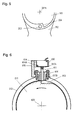
- Fig. 7 shows another conventional apparatus of adjusting an origin disclosed in Japanese Patent Laid-Open Publication No.2002-239967 .
- Member 712 is coupled rotatably with member 711, so that surface 712A of member 711 contacts surface 711A of member 711.
- Detachable positioning member 722 is mounted detachably to mounting port 723 of member 711.
- Member 712 has contact point 721 for contacting positioning member 722.
- Positioning member 722 is a positioning pin, while mounting port 723 is a tapped hole in which the positioning pin is screwed.
- an operation of the positioning member for contacting members 611 and 712 is not defined.
- An operator practically activates an arm with a teaching device until the positioning pin contacts the members.
- An operation of adjusting the origin requires accuracy, thus increasing a work load on the operator and increasing a working time.
- An erroneous handling by the operator during adjusting the origin may hurt the position pin and the arm.
- the operator attached detaches the positioning member. If the operator fails to attach the positioning member, the origin is not adjusted properly. If the operator fails to detach the positioning member after the adjusting of the origin adjustment and activates the robot, the positioning member and the arm of the robot arm may be damaged.
- An industrial robot includes a first member, a positioning member arranged to be attached to the first member, a second member arranged to rotate relatively to the first member, and a first joint for coupling the first member with the second member.
- the second member has a contact point arranged to contact the positioning member.
- An indication for requesting to enabling the positioning member to contact the contact point is displayed.
- the second member rotates at the first joint relatively to the first member while the positioning member can contact the contact point. It is detected whether or not the contact point of the second member contacts the positioning member.
- a position of the second member is stored as an origin when it is detected that the contact point of the second member contacts the positioning member.
- This method prevents a possible failure of the attaching of the positioning member, and decreases a work load on an operator.
- Fig. 1 is a schematic view of industrial robot 1 according to an exemplary embodiment of the present invention.
- Industrial robot 1 includes manipulator 101, tool 109 mounted on manipulator 101, controller 102 for controlling manipulator 101, and teaching device 108 used for activating manipulator 101 and controller 102.
- Tool 109 may be various devices, such as a welding torch and an opening/closing hand, according to the purpose.
- Controller 102 includes CPU 103, communication unit 104 for communicating with teaching device 108, ROM 105 storing a program allowing CPU 103 to operate, RAM 106 storing variable data, such as an operation program instructed by an operator and data for establishing an operating environment, and driver 107 for driving manipulator 101.
- ROM 105 and RAM 106 provide memory 105A.
- Manipulator 101 includes arms 202 and 201 rotating with respect to each other, base 1204, joint 1202 coupling arm 201 with arm 202, joint 1201 coupling arm 202 with base 1204, and joint 1203 coupling tool 109 and arm 201.
- Driver 107 of controller 102 controls respective motors of joints 1201 to 1203 to drive manipulator 101.
- An operation of industrial robot 1 will be described below.
- An operator inputs an instruction for activating manipulator 101 to teaching device 108.
- the instruction input to teaching device 108 is sent to controller 102, and is sent to CPU 103 via communication unit 104.
- CPU 103 controls driver 107 according to the instruction for activating manipulator 101.
- the operator moves arms 202 and 201 of manipulator 101 to a predetermined position and stance, and have the position and stance stored in RAM 106 through a registering operation through teaching device 108.
- the above processes provide an operation program.
- RAM 106 can store plural operation programs.
- the operator uses teaching device 108 to select a operation program executing the predetermined task from the operation programs stored in the memory.
- CPU 103 reads and interprets the selected operation program and controls manipulator 101 through driver 107 to have inductrial robot 1 execute the task.
- CPU 103 calculates angles of respective joint axes of joints 1201 to 1203 of manipulator 101. Before industrial robot 1 operates according to the operation program, the calculated angles are correlated to actual angles. That is, an origin, a reference of the angle of each joint axis, is adjusted. A method of adjusting the origin of industrial robot 1 will be described below.
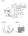
- Fig. 2A is a front view of joint 1202.
- Fig. 2B is a cross sectional view of joint 1202 at line 2B-2B.
- Arm 201 rotates about joint axis 201A relatively to arm 202.
- Positioning member 203 to be attached to arm 202 is a reference for adjusting the origin.
- contact point 204 contacts positioning member 203, thus setting an angle between arm 201 and arm 202 to a predetermined angle.
- Arm 201 is thus positioned with respect to arm 202, and the predetermined angle becomes the origin, the reference.
- Arm 202 has hole 202A therein for accommodating positioning member 203. While being accommodated in hole 202A, positioning member 203 does not protrudes from a surface, hence not contacting arm 201 regardless of the position of arm 201.
- Fig. 3 is a flow chart illustrating a method of adjusting the origin of industrial robot 1.
- Fig. 4A shows teaching device 108.
- Teaching device 108 includes display 402 and keyboard 403 for allowing the operator to input the instruction and data.
- Display 402 displays messages read out by CPU 103 from ROM 105.
- Figs. 4B to 4E show the messages displayed on display 402.
- the axis of joint 1202 is selected.
- display 402 displays an indication shown in Fig. 4B for requesting the operator to prevent positioning member 203 from contacting contact point 204 (Step 302). That is, in order to start adjusting the origin, display 402 indicates that arm 201 is to be moved to a stand-by position. Then, display 402 displays a message for having the operator cause positioning member 203 not to protrude, so that positioning member 203 is not damaged by collision with contact point 204 or arm 201. The operator checks the status of positioning member 203. If positioning member 203 protrudes from arm 202, the operator put positioning member 203 into hole 202A. In the case that the robot includes positioning member 722 shown in Fig. 7, positioning member 722 is detached from mounting port 723.
- keyboard 403 for moving arm 201 to a stand-by position for adjusting the origin, by pressing start key 403A of keyboard 403.
- a signal from keyboard 403 is sent from teaching device 108 to communication unit 104 of controller 102.
- CPU 103 activates driver 107 in accordance with the program stored in ROM 105, and activates only joint 1202 selected at Step 301 (Step 303).
- Fig. 5 is a front view of joint 1202 at Step 303.
- arm 201 rotates relatively to arm 202.
- arm 201 moves to the stand-by position.
- the stand-by position is defined as a position at which contact point 204 of arm 201 does not contact positioning member 203 but just before contacting positioning member 203.
- the stand-by position can be determined by angle A1 (see Fig. 1) between arm 201 and arm 202.
- the stand-by position can be, e.g. angle A1 of 100°, i.e., angle 10° calculated by CPU 103.
- the stand-by position can be referred to as a position at which positioning member does not contact arm 201.
- the stand-by position, angle of 10°, i.e., angle A1 of 100°, is stored in ROM 105. Angle A1 used for determining the stand-by position is not necessarily precise.
- the operator may position, with teaching device 108, one of arms 201 and 202 in a horizontal position while positioning the other of the arms in a vertical position, and then stores the positions of arms 201 and 202 in RAM 106 as a provisional position corresponding to angle of 0°.
- the position corresponding to the angle of 0° may be roughly determined, and then the position may be used as the basis for setting roughly the stand-by position corresponding to the angle of 10°.
- the angle of 0° calculated by CPU 103 does not necessarily correspond to angle A1 of 90°, but may correspond to other angle, such as 0°.
- the stand-by position may be determined by the operator with teaching device 108.
- the operator positions contact point 204 of arm 201 near positioning member 203 with teaching device 108, so that contact point 204 may not contact positioning member 203.
- the operator than store angle A1 (e.g. approximately 100°) between arms 201 and 202 in RAM 106 as the stand-by position.
- the stand-by position may not necessarily be precise as far as positioning member 203 does not contact arm 201. Therefore, the operator can determine the stand-by position easily.
- display 402 When arm 201 reaches the stand-by position, display 402 displays an indication for requesting to enable positioning member 203 to contact contact point 204 (Step 304). That is, display 402 displays a message shown in Fig. 4C for requesting the operator to execute an operation for having contact point 204 contact positioning member 203. Acknowledging the message, the operator take out positioning member 203 from hole 202A in arm 202 to have positioning member 203 protrude from arm 202. If the robot includes positioning member 722 shown in Fig. 7, the operator put positioning member 722 into the taped hole.
- Step 305 After causing positioning member 203 to protrude in accordance with the message shown in Fig. 4C, the operator presses keyboard 403 to instruct control device 102 to detect positioning member 203 (Step 305).
- arm 201 rotates relatively to arm 201 in a direction directing contact point 204 toward positioning member 203.
- controller 102 stops the rotation of arm 201.
- controller 102 detects that contact point 204 contacts positioning member 203.
- Contact point 204 contacts positioning member 203, then stopping the rotation of arm 201.
- Motor 1202A for rotating arm 201 at axis 201A of joint 1202 is loaded with an extra torque greater than that for rotating arm 201. This causes motor 1202A to have a current flowing therein larger than that usually required for rotating arm 201.
- CPU 103 detects, via driver 107, the current flowing in motor 1202A. When the detected current changes from a level smaller than a predetermined current to a level larger than the predetermined current, CPU 103 acknowledges that contact point 204 contacts positioning member 203. Then, CPU 103 immediately stops the rotation at joint 1202, and stores the angle at this moment in RAM 106 as the origin. In Fig. 2, contact point 204 of arm 201 contacts positioning member 203.
- controller 102 stops the rotation at joint 1202, display 402 displays a message shown in Fig. 4D for requesting the operator to execute an operation for restoring arm 201 to the stand-by position (Step 306).
- Step 307 the operator activates keyboard 403 to allow only joint 1202 selected at Step 301 to start moving and return to the stand-by position determined at Step 303 (Step 307).
- display 402 displays a message for requesting the operator to prevent positioning member 203 from contacting contact point 204 (Step 308). That is, display 402 displays a message shown in Fig. 4E for having the operator to execute an operation for causing positioning member 203 not to contact contact point 204.
- the operator puts positioning member 203 in hole 202a in arm 202 as to have positioning member 203 not to protrude from arm 202. If the robot includes positioning member 722 shown in Fig. 7, positioning member 722 is detached from mounting port 723. Then, it is confirmed that positioning member 203 cannot contact arm 201 (Step 309).
- controller 102 When judging that positioning member 203 cannot contact arm 201, controller 102 (CPU 103) may display this status on display 402. When judging that positioning member 203 contacts arm 201, controller 102 may display this status on display 402. Upon acknowledging this status, the operator confirms, at Steps 307 and 308, that the status of positioning member 203 so that positioning member 203 does not contact arm 201.
- angle A1 may range from 80° to 100° if the origin is the position of positioning member 203 corresponding to angle A1 of 90°.
- the value 100° of angle A1 is stored in ROM 105 or RAM 106.
- manipulator 101 automatically adjusts the origin sequentially in accordance with the program stored in ROM 105 and the instruction sent through teaching device 108, thereby reducing a work loaded on the operator, and reducing an operation time.
- the messages shown in Figs. 4A to 4E are displayed according to processes of adjusting the origin. This operation has the operator be aware of causing positioning member 203 not to protrude, that is, of disabling positioning member 203 to contact arm 201, thereby preventing positioning member 203 and arm 201 from damages.
- the joint to be adjusted is selected, and the selected joint is activated for adjusting the origin.
- plural joints may be selected.
- display 402 may display this situation.
- the origins at the joints may be adjusted within available moving ranges.
- the origins of the joints may be adjusted one by one. Only joints requiring the adjustment of their origin may be adjusted.
- a method of adjusting an origin for an industrial robot according to the present invention prevents an arm and a positioning member of the robot from damage. This method is effective for reducing a work loaded on an operator and reducing a time for the adjustment.
Landscapes
- Engineering & Computer Science (AREA)
- Robotics (AREA)
- Mechanical Engineering (AREA)
- Manipulator (AREA)
- Numerical Control (AREA)
Applications Claiming Priority (2)
| Application Number | Priority Date | Filing Date | Title |
|---|---|---|---|
| JP2005116864A JP2006289588A (ja) | 2005-04-14 | 2005-04-14 | 産業用ロボットの原点調整方法 |
| PCT/JP2005/019481 WO2006112069A1 (ja) | 2005-04-14 | 2005-10-24 | 産業用ロボットの原点調整方法 |
Publications (3)
| Publication Number | Publication Date |
|---|---|
| EP1785236A1 true EP1785236A1 (de) | 2007-05-16 |
| EP1785236A4 EP1785236A4 (de) | 2007-09-26 |
| EP1785236B1 EP1785236B1 (de) | 2008-07-23 |
Family
ID=37114813
Family Applications (1)
| Application Number | Title | Priority Date | Filing Date |
|---|---|---|---|
| EP05795720A Expired - Lifetime EP1785236B1 (de) | 2005-04-14 | 2005-10-24 | Ausgangsanpassungsverfahren für einen industrieroboter |
Country Status (7)
| Country | Link |
|---|---|
| US (1) | US7680551B2 (de) |
| EP (1) | EP1785236B1 (de) |
| JP (1) | JP2006289588A (de) |
| CN (1) | CN100537155C (de) |
| AT (1) | ATE401998T1 (de) |
| DE (1) | DE602005008448D1 (de) |
| WO (1) | WO2006112069A1 (de) |
Families Citing this family (14)
| Publication number | Priority date | Publication date | Assignee | Title |
|---|---|---|---|---|
| JP2009255196A (ja) * | 2008-04-14 | 2009-11-05 | Murata Mach Ltd | パラレルメカニズム |
| JP4674916B2 (ja) * | 2008-04-14 | 2011-04-20 | 村田機械株式会社 | パラレルメカニズム |
| JP5199815B2 (ja) * | 2008-10-08 | 2013-05-15 | 川崎重工業株式会社 | 原点位置調整機構、及びロボット |
| CN101444915B (zh) * | 2008-12-26 | 2011-05-11 | 北京理工大学 | 基于霍尔信号和电机轴z脉冲的机器人初始精确定位方法 |
| CN102114637A (zh) * | 2009-12-30 | 2011-07-06 | 鸿富锦精密工业(深圳)有限公司 | 机械手臂 |
| CN103085082B (zh) * | 2011-11-04 | 2015-10-14 | 鸿富锦精密工业(深圳)有限公司 | 机器人臂部件 |
| JP2015163414A (ja) * | 2014-02-28 | 2015-09-10 | ファナック株式会社 | 2つの部材の相対回転運動を規制する固定装置を備えるロボット、及び固定装置 |
| JP6054932B2 (ja) * | 2014-10-14 | 2016-12-27 | ファナック株式会社 | 線条体の長さの余裕を最適化できる関節構造、及び該関節構造を備えた産業用ロボット |
| JP6549843B2 (ja) * | 2014-12-26 | 2019-07-24 | 三菱プレシジョン株式会社 | パラレルリンク機構のキャリブレーション装置、キャリブレーション方法及びシミュレータ |
| JP6634088B2 (ja) * | 2015-09-08 | 2020-01-22 | 株式会社Fuji | 多関節ロボットアーム |
| JP2019118978A (ja) * | 2017-12-28 | 2019-07-22 | ファナック株式会社 | ロボットの固定システムおよびロボット |
| CN109093298A (zh) * | 2018-10-24 | 2018-12-28 | 东南(福建)汽车工业有限公司 | 一种焊接机器人机械原点的校正方法 |
| WO2020165989A1 (ja) * | 2019-02-14 | 2020-08-20 | 株式会社Fuji | 多関節ロボット |
| WO2022107704A1 (ja) * | 2020-11-20 | 2022-05-27 | ファナック株式会社 | 多関節型ロボット |
Family Cites Families (19)
| Publication number | Priority date | Publication date | Assignee | Title |
|---|---|---|---|---|
| US4481592A (en) * | 1982-03-05 | 1984-11-06 | Texas Instruments Incorporated | Calibration system for a programmable manipulator |
| US4632632A (en) | 1983-08-30 | 1986-12-30 | Automation Equipment Company | Programmable industrial robot having simplified construction |
| JPS6162103A (ja) * | 1984-09-03 | 1986-03-31 | Hitachi Ltd | 原点合せ順序を変更可能なロボツトシステム |
| JPS6377692A (ja) * | 1986-09-19 | 1988-04-07 | オムロン株式会社 | 作動範囲可変装置付き産業用ロボツト |
| JP2661735B2 (ja) | 1988-12-28 | 1997-10-08 | ファナック株式会社 | 産業用ロボット用原点調整装置 |
| JPH06210586A (ja) * | 1993-01-13 | 1994-08-02 | Fanuc Ltd | 各軸基準位置設定手段を備えた産業用ロボット |
| JPH07108484A (ja) * | 1993-10-07 | 1995-04-25 | Fanuc Ltd | ロボットの動作端検知装置 |
| JPH07266266A (ja) * | 1994-03-28 | 1995-10-17 | Fanuc Ltd | 産業用ロボットの基準位置設定方法 |
| KR100446167B1 (ko) * | 1995-09-18 | 2004-12-08 | 가부시키가이샤 야스가와덴끼 | 산업용로봇의스토퍼장치 |
| KR200145221Y1 (ko) | 1996-07-30 | 1999-06-15 | 윤종용 | 로봇 회전관절 스토퍼 |
| DE29717628U1 (de) | 1997-10-02 | 1998-02-19 | Morawski, Boleslaw, 58515 Lüdenscheid | Handhabungsgerät |
| JP4284765B2 (ja) * | 1999-07-27 | 2009-06-24 | 株式会社豊田中央研究所 | ロボットハンド位置計測装置 |
| DE60010609T2 (de) * | 1999-09-13 | 2005-07-28 | Fanuc Ltd. | Verbundsystem aus Roboter und Machine |
| JP2002239967A (ja) | 2001-02-14 | 2002-08-28 | Denso Corp | ロボット |
| FR2826897A1 (fr) * | 2001-07-04 | 2003-01-10 | Hpe | Mecanisme de chargement et de dechargement de boites renfermant des plaquettes de microelectronique pour le transfert de l'equipement a un chariot de transport, et inversement |
| KR100500964B1 (ko) * | 2002-05-14 | 2005-07-14 | 한국과학기술연구원 | 의료 시술 장치의 3차원 위치 측정 및 고정기구 |
| US6996456B2 (en) * | 2002-10-21 | 2006-02-07 | Fsi International, Inc. | Robot with tactile sensor device |
| JP4055691B2 (ja) * | 2003-10-03 | 2008-03-05 | 松下電器産業株式会社 | 産業用ロボット |
| JP4134994B2 (ja) * | 2005-03-30 | 2008-08-20 | 松下電器産業株式会社 | 産業用ロボット |
-
2005
- 2005-04-14 JP JP2005116864A patent/JP2006289588A/ja active Pending
- 2005-10-24 DE DE602005008448T patent/DE602005008448D1/de not_active Expired - Lifetime
- 2005-10-24 WO PCT/JP2005/019481 patent/WO2006112069A1/ja not_active Ceased
- 2005-10-24 CN CN200580001199.9A patent/CN100537155C/zh not_active Expired - Fee Related
- 2005-10-24 EP EP05795720A patent/EP1785236B1/de not_active Expired - Lifetime
- 2005-10-24 US US10/595,226 patent/US7680551B2/en active Active
- 2005-10-24 AT AT05795720T patent/ATE401998T1/de not_active IP Right Cessation
Also Published As
| Publication number | Publication date |
|---|---|
| WO2006112069A1 (ja) | 2006-10-26 |
| EP1785236A4 (de) | 2007-09-26 |
| CN1925953A (zh) | 2007-03-07 |
| JP2006289588A (ja) | 2006-10-26 |
| CN100537155C (zh) | 2009-09-09 |
| ATE401998T1 (de) | 2008-08-15 |
| DE602005008448D1 (de) | 2008-09-04 |
| US20080255701A1 (en) | 2008-10-16 |
| US7680551B2 (en) | 2010-03-16 |
| EP1785236B1 (de) | 2008-07-23 |
Similar Documents
| Publication | Publication Date | Title |
|---|---|---|
| EP1785236B1 (de) | Ausgangsanpassungsverfahren für einen industrieroboter | |
| US9776328B2 (en) | Robot control apparatus having function of detecting contact with object or person | |
| US10118295B2 (en) | Manual feed apparatus of robot for calculating operable range of robot | |
| EP1927909A2 (de) | Vorrichtung zur Korrektur einer Lehrposition | |
| CN109719376B (zh) | 机器人系统 | |
| CN109648585B (zh) | 监视作业工具的移动方向的控制装置 | |
| US20180222064A1 (en) | Movable robot | |
| JP7015267B2 (ja) | ロボット制御装置及びロボットシステム | |
| EP4046756A1 (de) | Mehrgelenk-roboter | |
| US20110173819A1 (en) | Operating method for a power tool, especially a hand-held power tool | |
| US20240269840A1 (en) | Method for controlling robot and arm | |
| KR101206241B1 (ko) | 로봇의 축 관리장치 및 방법 | |
| JP5202935B2 (ja) | 教示装置 | |
| CN1701930A (zh) | 配备动作区域检测装置的机器人关节的动作范围限制装置 | |
| JP2000288733A (ja) | 溶接ロボット自動原点チェック装置及びそのチェック方法 | |
| US20230311315A1 (en) | Robot control device, robot control method, and non-transitory computer-readable storage medium storing robot control program | |
| JP2020037165A (ja) | 動作プログラムの変数を監視するロボットの制御装置 | |
| KR20130009316A (ko) | 충격 센서가 내장된 로봇 제어 장치 및 이를 이용한 로봇 제어 방법 | |
| JP6754204B2 (ja) | 溶接トーチの芯ずれ検出装置 | |
| KR100190708B1 (ko) | 압력 센서를 이용한 부품 자동 조립 로보트 | |
| CN116890333B (zh) | 机器人控制装置、机器人控制方法及存储介质 | |
| CN121843796A (zh) | 机器人控制装置 | |
| US20240269763A1 (en) | Device for measuring wear amount of welding tip, control device, robot system, method, and computer program | |
| JP2007061834A (ja) | ロボット・シーム溶接システムの電極摩耗量検出方法および装置 | |
| JP2023147725A (ja) | ロボット制御装置、ロボット制御方法およびロボット制御プログラム |
Legal Events
| Date | Code | Title | Description |
|---|---|---|---|
| PUAI | Public reference made under article 153(3) epc to a published international application that has entered the european phase |
Free format text: ORIGINAL CODE: 0009012 |
|
| 17P | Request for examination filed |
Effective date: 20060321 |
|
| AK | Designated contracting states |
Kind code of ref document: A1 Designated state(s): AT BE BG CH CY CZ DE DK EE ES FI FR GB GR HU IE IS IT LI LT LU LV MC NL PL PT RO SE SI SK TR |
|
| AX | Request for extension of the european patent |
Extension state: AL BA HR MK YU |
|
| A4 | Supplementary search report drawn up and despatched |
Effective date: 20070829 |
|
| GRAP | Despatch of communication of intention to grant a patent |
Free format text: ORIGINAL CODE: EPIDOSNIGR1 |
|
| DAX | Request for extension of the european patent (deleted) | ||
| GRAS | Grant fee paid |
Free format text: ORIGINAL CODE: EPIDOSNIGR3 |
|
| GRAA | (expected) grant |
Free format text: ORIGINAL CODE: 0009210 |
|
| AK | Designated contracting states |
Kind code of ref document: B1 Designated state(s): AT BE BG CH CY CZ DE DK EE ES FI FR GB GR HU IE IS IT LI LT LU LV MC NL PL PT RO SE SI SK TR |
|
| REG | Reference to a national code |
Ref country code: GB Ref legal event code: FG4D |
|
| REG | Reference to a national code |
Ref country code: CH Ref legal event code: EP |
|
| REG | Reference to a national code |
Ref country code: IE Ref legal event code: FG4D |
|
| REF | Corresponds to: |
Ref document number: 602005008448 Country of ref document: DE Date of ref document: 20080904 Kind code of ref document: P |
|
| REG | Reference to a national code |
Ref country code: SE Ref legal event code: TRGR |
|
| RAP2 | Party data changed (patent owner data changed or rights of a patent transferred) |
Owner name: PANASONIC CORPORATION |
|
| NLT2 | Nl: modifications (of names), taken from the european patent patent bulletin |
Owner name: PANASONIC CORPORATION Effective date: 20081119 |
|
| PG25 | Lapsed in a contracting state [announced via postgrant information from national office to epo] |
Ref country code: LT Free format text: LAPSE BECAUSE OF FAILURE TO SUBMIT A TRANSLATION OF THE DESCRIPTION OR TO PAY THE FEE WITHIN THE PRESCRIBED TIME-LIMIT Effective date: 20080723 Ref country code: IS Free format text: LAPSE BECAUSE OF FAILURE TO SUBMIT A TRANSLATION OF THE DESCRIPTION OR TO PAY THE FEE WITHIN THE PRESCRIBED TIME-LIMIT Effective date: 20081123 |
|
| PG25 | Lapsed in a contracting state [announced via postgrant information from national office to epo] |
Ref country code: BG Free format text: LAPSE BECAUSE OF FAILURE TO SUBMIT A TRANSLATION OF THE DESCRIPTION OR TO PAY THE FEE WITHIN THE PRESCRIBED TIME-LIMIT Effective date: 20081023 Ref country code: PT Free format text: LAPSE BECAUSE OF FAILURE TO SUBMIT A TRANSLATION OF THE DESCRIPTION OR TO PAY THE FEE WITHIN THE PRESCRIBED TIME-LIMIT Effective date: 20081223 Ref country code: AT Free format text: LAPSE BECAUSE OF FAILURE TO SUBMIT A TRANSLATION OF THE DESCRIPTION OR TO PAY THE FEE WITHIN THE PRESCRIBED TIME-LIMIT Effective date: 20080723 Ref country code: SI Free format text: LAPSE BECAUSE OF FAILURE TO SUBMIT A TRANSLATION OF THE DESCRIPTION OR TO PAY THE FEE WITHIN THE PRESCRIBED TIME-LIMIT Effective date: 20080723 Ref country code: FI Free format text: LAPSE BECAUSE OF FAILURE TO SUBMIT A TRANSLATION OF THE DESCRIPTION OR TO PAY THE FEE WITHIN THE PRESCRIBED TIME-LIMIT Effective date: 20080723 Ref country code: ES Free format text: LAPSE BECAUSE OF FAILURE TO SUBMIT A TRANSLATION OF THE DESCRIPTION OR TO PAY THE FEE WITHIN THE PRESCRIBED TIME-LIMIT Effective date: 20081103 Ref country code: LV Free format text: LAPSE BECAUSE OF FAILURE TO SUBMIT A TRANSLATION OF THE DESCRIPTION OR TO PAY THE FEE WITHIN THE PRESCRIBED TIME-LIMIT Effective date: 20080723 |
|
| PG25 | Lapsed in a contracting state [announced via postgrant information from national office to epo] |
Ref country code: BE Free format text: LAPSE BECAUSE OF FAILURE TO SUBMIT A TRANSLATION OF THE DESCRIPTION OR TO PAY THE FEE WITHIN THE PRESCRIBED TIME-LIMIT Effective date: 20080723 |
|
| PG25 | Lapsed in a contracting state [announced via postgrant information from national office to epo] |
Ref country code: DK Free format text: LAPSE BECAUSE OF FAILURE TO SUBMIT A TRANSLATION OF THE DESCRIPTION OR TO PAY THE FEE WITHIN THE PRESCRIBED TIME-LIMIT Effective date: 20080723 Ref country code: EE Free format text: LAPSE BECAUSE OF FAILURE TO SUBMIT A TRANSLATION OF THE DESCRIPTION OR TO PAY THE FEE WITHIN THE PRESCRIBED TIME-LIMIT Effective date: 20080723 |
|
| PG25 | Lapsed in a contracting state [announced via postgrant information from national office to epo] |
Ref country code: SK Free format text: LAPSE BECAUSE OF FAILURE TO SUBMIT A TRANSLATION OF THE DESCRIPTION OR TO PAY THE FEE WITHIN THE PRESCRIBED TIME-LIMIT Effective date: 20080723 Ref country code: CZ Free format text: LAPSE BECAUSE OF FAILURE TO SUBMIT A TRANSLATION OF THE DESCRIPTION OR TO PAY THE FEE WITHIN THE PRESCRIBED TIME-LIMIT Effective date: 20080723 Ref country code: RO Free format text: LAPSE BECAUSE OF FAILURE TO SUBMIT A TRANSLATION OF THE DESCRIPTION OR TO PAY THE FEE WITHIN THE PRESCRIBED TIME-LIMIT Effective date: 20080723 Ref country code: MC Free format text: LAPSE BECAUSE OF NON-PAYMENT OF DUE FEES Effective date: 20081031 |
|
| PLBE | No opposition filed within time limit |
Free format text: ORIGINAL CODE: 0009261 |
|
| STAA | Information on the status of an ep patent application or granted ep patent |
Free format text: STATUS: NO OPPOSITION FILED WITHIN TIME LIMIT |
|
| 26N | No opposition filed |
Effective date: 20090424 |
|
| NLV4 | Nl: lapsed or anulled due to non-payment of the annual fee |
Effective date: 20090501 |
|
| REG | Reference to a national code |
Ref country code: FR Ref legal event code: ST Effective date: 20090630 |
|
| PG25 | Lapsed in a contracting state [announced via postgrant information from national office to epo] |
Ref country code: IT Free format text: LAPSE BECAUSE OF FAILURE TO SUBMIT A TRANSLATION OF THE DESCRIPTION OR TO PAY THE FEE WITHIN THE PRESCRIBED TIME-LIMIT Effective date: 20080723 |
|
| PG25 | Lapsed in a contracting state [announced via postgrant information from national office to epo] |
Ref country code: IE Free format text: LAPSE BECAUSE OF NON-PAYMENT OF DUE FEES Effective date: 20081024 Ref country code: FR Free format text: LAPSE BECAUSE OF NON-PAYMENT OF DUE FEES Effective date: 20081031 |
|
| REG | Reference to a national code |
Ref country code: GB Ref legal event code: 746 Effective date: 20091221 |
|
| PG25 | Lapsed in a contracting state [announced via postgrant information from national office to epo] |
Ref country code: PL Free format text: LAPSE BECAUSE OF FAILURE TO SUBMIT A TRANSLATION OF THE DESCRIPTION OR TO PAY THE FEE WITHIN THE PRESCRIBED TIME-LIMIT Effective date: 20080723 |
|
| REG | Reference to a national code |
Ref country code: CH Ref legal event code: PL |
|
| PG25 | Lapsed in a contracting state [announced via postgrant information from national office to epo] |
Ref country code: LU Free format text: LAPSE BECAUSE OF NON-PAYMENT OF DUE FEES Effective date: 20081024 Ref country code: CY Free format text: LAPSE BECAUSE OF FAILURE TO SUBMIT A TRANSLATION OF THE DESCRIPTION OR TO PAY THE FEE WITHIN THE PRESCRIBED TIME-LIMIT Effective date: 20080723 Ref country code: HU Free format text: LAPSE BECAUSE OF FAILURE TO SUBMIT A TRANSLATION OF THE DESCRIPTION OR TO PAY THE FEE WITHIN THE PRESCRIBED TIME-LIMIT Effective date: 20090124 |
|
| PG25 | Lapsed in a contracting state [announced via postgrant information from national office to epo] |
Ref country code: TR Free format text: LAPSE BECAUSE OF FAILURE TO SUBMIT A TRANSLATION OF THE DESCRIPTION OR TO PAY THE FEE WITHIN THE PRESCRIBED TIME-LIMIT Effective date: 20080723 |
|
| PG25 | Lapsed in a contracting state [announced via postgrant information from national office to epo] |
Ref country code: LI Free format text: LAPSE BECAUSE OF NON-PAYMENT OF DUE FEES Effective date: 20091031 Ref country code: GR Free format text: LAPSE BECAUSE OF FAILURE TO SUBMIT A TRANSLATION OF THE DESCRIPTION OR TO PAY THE FEE WITHIN THE PRESCRIBED TIME-LIMIT Effective date: 20081024 Ref country code: CH Free format text: LAPSE BECAUSE OF NON-PAYMENT OF DUE FEES Effective date: 20091031 |
|
| PGFP | Annual fee paid to national office [announced via postgrant information from national office to epo] |
Ref country code: NL Payment date: 20180912 Year of fee payment: 14 |
|
| PGFP | Annual fee paid to national office [announced via postgrant information from national office to epo] |
Ref country code: SE Payment date: 20181011 Year of fee payment: 14 |
|
| REG | Reference to a national code |
Ref country code: NL Ref legal event code: MM Effective date: 20191101 |
|
| PG25 | Lapsed in a contracting state [announced via postgrant information from national office to epo] |
Ref country code: NL Free format text: LAPSE BECAUSE OF NON-PAYMENT OF DUE FEES Effective date: 20191101 Ref country code: SE Free format text: LAPSE BECAUSE OF NON-PAYMENT OF DUE FEES Effective date: 20191025 |
|
| PGFP | Annual fee paid to national office [announced via postgrant information from national office to epo] |
Ref country code: DE Payment date: 20201013 Year of fee payment: 16 Ref country code: GB Payment date: 20201014 Year of fee payment: 16 |
|
| REG | Reference to a national code |
Ref country code: DE Ref legal event code: R119 Ref document number: 602005008448 Country of ref document: DE |
|
| GBPC | Gb: european patent ceased through non-payment of renewal fee |
Effective date: 20211024 |
|
| PG25 | Lapsed in a contracting state [announced via postgrant information from national office to epo] |
Ref country code: GB Free format text: LAPSE BECAUSE OF NON-PAYMENT OF DUE FEES Effective date: 20211024 Ref country code: DE Free format text: LAPSE BECAUSE OF NON-PAYMENT OF DUE FEES Effective date: 20220503 |