EP1785237A2 - Robotersteuerungsvorrichtung - Google Patents
Robotersteuerungsvorrichtung Download PDFInfo
- Publication number
- EP1785237A2 EP1785237A2 EP06022246A EP06022246A EP1785237A2 EP 1785237 A2 EP1785237 A2 EP 1785237A2 EP 06022246 A EP06022246 A EP 06022246A EP 06022246 A EP06022246 A EP 06022246A EP 1785237 A2 EP1785237 A2 EP 1785237A2
- Authority
- EP
- European Patent Office
- Prior art keywords
- robot
- emergency stop
- disconnection
- power supply
- supply line
- Prior art date
- Legal status (The legal status is an assumption and is not a legal conclusion. Google has not performed a legal analysis and makes no representation as to the accuracy of the status listed.)
- Granted
Links
Images


Classifications
-
- B—PERFORMING OPERATIONS; TRANSPORTING
- B25—HAND TOOLS; PORTABLE POWER-DRIVEN TOOLS; MANIPULATORS
- B25J—MANIPULATORS; CHAMBERS PROVIDED WITH MANIPULATION DEVICES
- B25J9/00—Program-controlled manipulators
- B25J9/16—Program controls
- B25J9/1674—Program controls characterised by safety, monitoring, diagnostic
-
- G—PHYSICS
- G05—CONTROLLING; REGULATING
- G05B—CONTROL OR REGULATING SYSTEMS IN GENERAL; FUNCTIONAL ELEMENTS OF SUCH SYSTEMS; MONITORING OR TESTING ARRANGEMENTS FOR SUCH SYSTEMS OR ELEMENTS
- G05B2219/00—Program-control systems
- G05B2219/30—Nc systems
- G05B2219/39—Robotics, robotics to robotics hand
- G05B2219/39447—Dead man switch
-
- G—PHYSICS
- G05—CONTROLLING; REGULATING
- G05B—CONTROL OR REGULATING SYSTEMS IN GENERAL; FUNCTIONAL ELEMENTS OF SUCH SYSTEMS; MONITORING OR TESTING ARRANGEMENTS FOR SUCH SYSTEMS OR ELEMENTS
- G05B2219/00—Program-control systems
- G05B2219/30—Nc systems
- G05B2219/40—Robotics, robotics mapping to robotics vision
- G05B2219/40202—Human robot coexistence
-
- G—PHYSICS
- G05—CONTROLLING; REGULATING
- G05B—CONTROL OR REGULATING SYSTEMS IN GENERAL; FUNCTIONAL ELEMENTS OF SUCH SYSTEMS; MONITORING OR TESTING ARRANGEMENTS FOR SUCH SYSTEMS OR ELEMENTS
- G05B2219/00—Program-control systems
- G05B2219/30—Nc systems
- G05B2219/40—Robotics, robotics mapping to robotics vision
- G05B2219/40218—Check conditions before allowing unlocking of joint brake
-
- G—PHYSICS
- G05—CONTROLLING; REGULATING
- G05B—CONTROL OR REGULATING SYSTEMS IN GENERAL; FUNCTIONAL ELEMENTS OF SUCH SYSTEMS; MONITORING OR TESTING ARRANGEMENTS FOR SUCH SYSTEMS OR ELEMENTS
- G05B2219/00—Program-control systems
- G05B2219/30—Nc systems
- G05B2219/50—Machine tool, machine tool null till machine tool work handling
- G05B2219/50198—Emergency stop
Definitions
- the present invention relates to a robot control device and, more particularly, to a robot control device capable of switching between a first operation mode for preventing an operator from approaching a robot working area when power is supplied to a drive motor for driving the robot and a second operation mode for allowing an operator to approach the robot working area even when power is supplied to the drive motor.
- a robot is generally operated automatically. Therefore, if an operator carelessly intrudes into a robot working area, the operator may collide with the robot.
- the robot operation is forcibly stopped to secure the operator's safety.
- a robot control device senses, based on the output from a door switch or a safety plug mounted on the door of the guard fence, that the door of the guard fence is opened, it determines that the operator has entered the area within the guard fence and immediately brings the robot to an emergency stop by cutting off the power supply to the robot.
- the robot control device senses that light of the light curtain has been intercepted, determines that the operator has entered the area within the robot working area and immediately stops the robot by cutting off the power supplied to the robot.
- the operator when teaching the robot about an operation, the operator is required to enter the robot working area through the door of the guard fence or the light curtain and perform the teaching job by operating the powered robot through a teaching pendant. Therefore, in addition to an automatic operation mode for sensing the intrusion of the operator into the robot working area and bringing the robot to an emergency stop, it is common practice to provide the robot control device with a teaching operation mode for allowing the robot to be operated without an emergency stop even if the operator enters the robot working area. In the teaching operation mode, the operator can operate an operation mode change-over switch on a fixed operation panel of the robot control device to switch between the automatic operation mode and the teaching operation mode.
- the signal from the door of the guard fence or the light curtain is invalidated even when the door of the guard fence is opened or the operator intrudes into the robot working area through the light curtain, so that the operator can operate the robot from the teaching pendant without stopping the robot as an emergency.
- an emergency stop button and a deadman switch are provided on the teaching pendant, so that the robot can be operated only while depressing the deadman switch. The operator, whenever danger is perceived, can release the deadman switch, or depress the emergency stop button on the teaching pendant, to thereby bring the robot to an emergency stop even in the teaching operation mode.
- the robot can be brought to an emergency by operating the emergency stop button or the deadman switch even in the teaching operation mode.
- an emergency stop circuit functions normally upon depression of the emergency stop button or operation of the deadman switch.
- the emergency stop circuit is checked manually by the operator, and therefore the check job is sometimes forgotten or intentionally omitted.
- the safety of the operator cannot be secured in some cases where the emergency stop circuit fails and an emergency stop cannot be carried out.
- a robot control device which includes an operation mode change-over switch for switching between a first operation mode for prohibiting an operator from approaching a predetermined area around a robot when power is supplied to a drive motor for driving the robot and a second operation mode for allowing the operator to approach the predetermined area around the robot even when power is supplied to the drive motor, and a connection/disconnection means for switching the connection and disconnection of a power supply line to the drive motor, the robot being stopped in case of emergency by using the connection/disconnection means to disconnect the power supply line, wherein the robot control device further includes an emergency stop control unit, the emergency stop control unit issuing a , disconnection command, to the connection/disconnection means, when the switching between the first and second operation modes by the operation mode change-over switch is sensed, and automatically confirming whether or not the power supply line is disconnected.
- the emergency stop control unit of the robot control device automatically confirms that the power supply line is disconnected by the connection/disconnection means in accordance with the disconnection command at the time of switching the operation mode.
- the connection/disconnection means receives the disconnection command to thereby disconnect the power supply to the drive motor for driving the robot, with the result that the emergency stop of the robot is detected. Therefore, the normal performance of the emergency stop function can be confirmed and the operator is not required to check the emergency stop function manually.
- connection/disconnection means may output a connection/disconnection state signal indicating whether the power supply line is connected or disconnected, and the emergency stop control unit may confirm whether or not the power supply line is disconnected based on the connection/disconnection state signal.
- the emergency stop control unit issues an alarm when the emergency stop control unit fails to confirm the disconnection of the power supply line in spite of the issuance of a disconnection command to the connection/disconnection means.
- the emergency stop control unit may prohibit the reconnection of the power supply line by the connection/disconnection means when the emergency stop control unit fails to confirm the disconnection of the power supply line in spite of the issuance of a disconnection command to the connection/disconnection means. This can prevent the operator from operating the robot in the state where the emergency stop function provided by the connection/disconnection means fails to normally work.
- the emergency stop control unit automatically confirms that the connection/disconnection means receives the disconnection command thereby disconnect the power supply to the drive motor.
- an emergency stop of the robot can be confirmed and, therefore, the operator is not required to check the function of the emergency stop circuit.
- a robot control device higher in safety than in the prior art is provided.
- a guard fence 15 is provided around the robot 13, and the working area of the robot 13 is limited to within the guard fence 15. Therefore, as long as the operator is located outside the guard fence, interference between the operator and the robot 13 is avoided.
- One or more doors 17 or openings 19 through which the operator can enter the robot working area are provided in the guard fence 15.
- a door switch 21a or a safety plug (not shown) is mounted on the door 17 of the guard fence 15 and is adapted to sense that the door 17 of the guard fence 15 is open.
- a light curtain 21b is provided at the opening 19 so that the operator passing across the light curtain 21b is sensed by detecting the interception of the light of the light curtain 21b.
- the operation of the robot 13 disposed in the robot cell 11 is controlled by a robot control device 23.
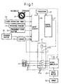
- the robot control device 23 includes a fixed operation panel 25 for the operator to operate the robot 13 in the normal operation, a teaching pendant 27 for the operator to operate the robot 13 in the teaching job, and an emergency stop circuit 29 (Fig. 1). Also, the robot control device 23 is connected wirelessly or through cable to a sensor 21 such as a door switch 21a or a light curtain 21b of the guard fence 15.
- the fixed operation panel 25 is arranged outside the guard fence 15, and can be operated by the operator only when he/she is located outside the guard fence 15.
- the teaching pendant 27 can be carried by the operator within the guard fence 15 during the teaching job, and is preferably wirelessly connected to the robot control device 23 so as not to obstruct the job.
- the fixed operation panel 25 is provided with an operation mode change-over switch 31 (Fig. 1) to switch between the automatic operation mode and the teaching operation mode.
- the fixed operation panel 25 is provided thereon with an emergency stop button 33 to forcibly stop the robot 13 in case of an emergency
- the teaching pendant 27 is provided thereon with an emergency stop button 33 and a deadman switch 35 having a similar function.
- the emergency stop circuit 29 of the robot control device 23 is configured of, as shown in Fig. 1, a processor 37 for processing the various signals and commands, an input circuit 39 enabling the processor 37 to read various signals, an output circuit 41 for outputting signals from the processor 37, and an electromagnetic contactor 51 functioning as an connection/disconnection means to switch the connection and disconnection of a power supply line 49 connecting a power supply 47 and a servo amplifier 45 for actuating a drive motor 43 for driving the robot 13.
- the input circuit 39 is connected, through a signal cable, with the operation mode change-over switch 31 on the fixed operation panel 25, the emergency stop buttons 33 on the fixed operation panel 25 and the teaching pendant 27 and the sensors 21 such as the door switch 21a of the guard fence 15 and the light curtain 21b.
- the output signals from these devices are read into the processor 37 through the input circuit 39.
- the processor 37 determines whether or not the conditions to stop the robot 13 as an emergency are fulfilled, based on the output signals from the sensors 21, the output signals from the emergency stop buttons 33 and the output signal from the deadman switch 35 and, if it is determined that the emergency stop conditions are fulfilled, immediately issues a disconnection command to the electromagnetic contactor 51 through the output circuit 41 to thereby open the electromagnetic contactor 51.
- the power supply line 49 is disconnected and the power from the power supply 47 to the servo amplifier 45 is stopped, thereby allowing the robot 13 to be brought to an emergency stop.
- the robot control device 23 executes a different process for a different state of the operation mode change-over switch 31.
- the automatic operation mode is used for automatic operation of the robot 13.
- the robot control device 23 receives the command from the fixed operation panel 25 to start or stop the automatic operation.
- the processor 37 of the emergency stop circuit 29 of the robot control device 23 monitors the signal from the sensor 21 such as the door switch 21a or the light curtain 21b of the guard fence 15.
- the processor 37 When the processor 37 senses the entry of the operator through the guard fence 15 while the power is supplied to the drive motor 43 for driving the robot 13, it determines that the emergency stop conditions are fulfilled and then immediately issued a disconnection command to the electromagnetic contactor 51 to thereby disconnect the power supply line 49 between the power supply 47 and the robot 13 and stop the robot as an emergency. Also, when the emergency stop button 33 on the fixed operation panel 25 is depressed, a process for bringing the robot 13 to an emergency stop is executed in similar fashion.
- the teaching operation mode is used for carrying out the job of teaching the robot 13.
- the robot control device 23 does not accept the command to start the automatic operation from the fixed operation panel 25, and accepts only the operation command from the teaching pendant 27.
- the maximum moving speed of the forward end of the arm of the robot 13 due to the operation command is limited to not more than a safe speed of, for example, 250 mm/sec.
- the processor 37 of the emergency stop circuit 29 of the robot control device 23 determines that the emergency stop conditions are not fulfilled and does not control the robot 13 for emergency stop, even when it senses the intrusion of the operator through the guard fence 15 based on the output of the sensors 21 provided on the guard fence 15. This is because, in the case where the robot 13 is taught about the operation route, the operator is required to enter the robot working area inside of the guard fence and operate the robot 13 supplied with power.
- the processor 37 does not disregard but carefully monitors the signals from the emergency stop button 33 and the deadman switch 35 provided on the teaching pendant 27.
- the processor 37 senses that the deadman switch 35 is opened or gripped firmly or the emergency stop button 33 is depressed, it determines that the emergency stop conditions are fulfilled and immediately issues a disconnection command to the electromagnetic contactor 51 to thereby disconnect the power supply line 49 between the power supply 47 and the robot 13 and bring the robot 13 to an emergency.
- the robot control device 23 further includes a function, added to the processor, of an emergency stop control unit for automatically checking the operation of the emergency stop circuit 29 before starting the teaching job.
- a type of electromagnetic contactor including an auxiliary monitor contact 51b for outputting a signal indicating the connection/disconnection state of a contact in addition to the operation contact 51a for connecting/disconnecting the power supply line is used as the electromagnetic contactor 51.
- the output of the auxiliary monitor contact 51b is input to the input circuit 39 and read into the processor 37.
- the processor 37 functioning as an emergency stop control unit senses, based on a change of the signal from the operation mode change-over switch 31, that the operation mode is switched by the operator, it specifically executes a procedure of confirming the function of the emergency stop circuit 29 as described below with reference to Fig. 2.
- the processor 37 of the emergency stop circuit 29 of the robot control device 23 by reading the signal from the operation mode change-over switch 31 on the fixed operation panel 25 through the input circuit 39, always monitors the state of the same switch 31 and senses that the operator switches the operation mode (step S1). Once the operation mode is switched by the operator from the automatic operation mode to the teaching operation mode, the processor 37 issues a disconnection command to the electromagnetic contactor 51 through the output circuit 41 (step S2).
- the electromagnetic contactor 51 in accordance with the disconnection command, opens the operation contact 51a and disconnects the power supply line 49 between the servo amplifier 45 and the power supply 47 to stop power supplied to the servo amplifier 45.
- the auxiliary monitor contact 51b of the electromagnetic contactor 51 is closed (in the on-state).
- the power supply line 49 is connected, i.e. the operation contact 51a in the electromagnetic contactor 51 is closed, the auxiliary monitor contact 51b of the electromagnetic contactor 51 is opened (in the off-state).
- the processor 37 by reading the state of the auxiliary monitor contact 51b through the input circuit 39, confirms whether or not the operation contact 51a of the electromagnetic contactor 51 is opened and the power supply line 49 is disconnected by the electromagnetic contactor 51 in accordance with the command (step S3).
- step S4 the processor 37 determines that the emergency stop circuit 29 including the electromagnetic contactor 51 and the driver circuit is at fault (step S4).
- the processor 37 displays or outputs an alarm on the fixed operation panel 25 and the teaching pendant 27, and at the same time prohibits the operator from manipulating the teaching pendant 27 to make the electromagnetic contactor 51 in the closed state (in the state where the power supply line 49 is connected), thereby making it impossible for the operator to reactivate the robot 13.
- the power supply line 49 is kept disconnected and the drive motor 43 for driving the robot 13 cannot be activated.
- the operator cannot perform the teaching job any longer, and therefore the teaching job is prevented from being erroneously carried out while the emergency stop circuit 29 is at fault.
- step S6 the state of the emergency stop circuit 29 being not at fault is confirmed.
- the processor 37 issues a connection command to the electromagnetic contactor 51 if the emergency stop is not output from the emergency stop button 33 or otherwise conditions to stop the robot 13 are not fulfilled.
- the electromagnetic contactor 51 makes the operation contact 51a in closed state in accordance with the connection command to thereby connect the power supply line 49 between the servo amplifier 45 and the power supply 47.
- the processor 37 may leave the electromagnetic contactor 51 disconnected until the operator performs the operation to reactivate the robot 13 by means of the teaching pendant 27. In this case, the operation for reactivation is performed in the manner described below.
- the operator after switching the operation mode change-over switch to the teaching operation mode and holding the teaching pendant 27, enters into the inside of the guard fence 15 by opening the door 17 of the guard fence 15 or through the light curtain 21b and approaches the robot 13.
- the operator grips the deadman switch 35 of the teaching pendant 27 and depresses the reset key on the teaching pendant 27.
- the processor 37 issues a connection command to the electromagnetic contactor 51 to connect the power supply line 49 between the servo amplifier 45 and the power supply 47. As a result, the supply of power to the servo amplifier 45 is recommenced, so that the robot 13 can again be driven by the drive motor 43.
- the processor 37 issues no connection command to the electromagnetic contactor 51 even if the operator depresses the reset key, and an alarm screen is displayed on the fixed operation panel 25 and the teaching pendant 27. As a result, the operator can look at the display on the teaching pendant 27 and recognize that the emergency stop circuit 29 is at fault.
- the operation check of the emergency stop circuit 29 may not be carried out accurately.
- this problem can be obviated by confirming that the signal of the auxiliary monitor contact 51b is switched between the on and the off states when the processor 37 issues a disconnection command or a connection command to the electromagnetic contactor 51.
- the signal of the auxiliary monitor contact 51b is changed to the closed state (on-state) from the open state (off-state) when the processor gives a connection command to the electromagnetic contactor 51, the input circuit 39 or the auxiliary monitor contact 51b is determined as at fault, and an alarm is displayed or otherwise issued.
- the processor 37 functioning as an emergency stop control unit senses that the operator has switched the operation mode change-over switch 31 to the teaching operation mode, it issues a disconnection command to the electromagnetic contactor 51, and only after the fact that the electromagnetic contactor 51 disconnects the power supply line 49 in accordance with the command is confirmed by the signal of the auxiliary monitor contact 51b, allows the operator to reactivate the robot 13.
- the function of the emergency stop circuit 29 has already been checked automatically and the absence of a fault has been confirmed, thereby eliminating the need of a conscious check of the emergency stop circuit 29 by the operator. In this way, the function of the emergency stop circuit 29 is positively confirmed prior to the start of a teaching job involving the risk of the robot 13 causing harm to the operator, thereby making it possible to secure a higher safety of the operator.
- the emergency stop circuit 29 is checked by the emergency stop control unit when the operation mode is switched from the automatic operation mode to the teaching operation mode.
- the emergency stop circuit 29 can also be checked according to a procedure similar to the above-described procedure when the operation mode is switched from the teaching operation mode to the automatic operation mode or the robot control device 23 is activated.
- one electromagnetic contactor 51 is used for the emergency stop circuit 9.
- two or more electromagnetic contactors 51 may be connected in series and the circuit may be multiplied to improve the reliability of the emergency stop circuit 29.
Landscapes
- Engineering & Computer Science (AREA)
- Robotics (AREA)
- Mechanical Engineering (AREA)
- Manipulator (AREA)
- Numerical Control (AREA)
Applications Claiming Priority (1)
| Application Number | Priority Date | Filing Date | Title |
|---|---|---|---|
| JP2005314465A JP4137932B2 (ja) | 2005-10-28 | 2005-10-28 | ロボット制御装置 |
Publications (3)
| Publication Number | Publication Date |
|---|---|
| EP1785237A2 true EP1785237A2 (de) | 2007-05-16 |
| EP1785237A3 EP1785237A3 (de) | 2008-10-22 |
| EP1785237B1 EP1785237B1 (de) | 2011-06-08 |
Family
ID=37895827
Family Applications (1)
| Application Number | Title | Priority Date | Filing Date |
|---|---|---|---|
| EP06022246A Active EP1785237B1 (de) | 2005-10-28 | 2006-10-24 | Robotersteuerungsvorrichtung |
Country Status (4)
| Country | Link |
|---|---|
| US (1) | US7501778B2 (de) |
| EP (1) | EP1785237B1 (de) |
| JP (1) | JP4137932B2 (de) |
| CN (1) | CN100528493C (de) |
Cited By (6)
| Publication number | Priority date | Publication date | Assignee | Title |
|---|---|---|---|---|
| WO2010009488A3 (de) * | 2008-07-21 | 2010-07-01 | Keba Ag | Verfahren zum betreiben eines mobilen handbediengerätes für die abgabe oder freischaltung von potentiell gefahrbringenden steuerkommandos sowie entsprechendes handbediengerät |
| EP2030741A3 (de) * | 2007-08-27 | 2010-12-01 | Fanuc Ltd | Robotersteuerung mit Ausfallüberwachungsfunktion |
| WO2011015791A1 (fr) * | 2009-08-07 | 2011-02-10 | Biotope | Contrôle d'une installation en fonction de la dangerosité de son interaction avec une espèce animale |
| WO2011104199A1 (de) * | 2010-02-23 | 2011-09-01 | Ifm Electronic Gmbh | Überwachungssystem |
| US10152043B2 (en) | 2016-03-11 | 2018-12-11 | Fanuc Corporation | Robot system |
| US12465944B2 (en) | 2019-09-30 | 2025-11-11 | Dürr Systems Ag | Treatment system and treatment method |
Families Citing this family (71)
| Publication number | Priority date | Publication date | Assignee | Title |
|---|---|---|---|---|
| EP1935929B1 (de) * | 2006-12-19 | 2011-11-30 | Evonik Degussa GmbH | Sol-Gel-Prozess zur Herstellung von Schutzfolien für Polymersubstrate |
| WO2009060534A1 (ja) * | 2007-11-09 | 2009-05-14 | Idec Corporation | 電子機器の取付構造及びこれを備えた産業機械システム |
| JP5375297B2 (ja) * | 2009-04-16 | 2013-12-25 | 株式会社安川電機 | ロボットシステム |
| JP5447937B2 (ja) * | 2009-08-19 | 2014-03-19 | 株式会社ダイフク | 物品搬送設備 |
| DE102009038721A1 (de) * | 2009-08-25 | 2011-03-03 | Kuka Roboter Gmbh | Anordnung und Verfahren zur sicheren Steuerung eines Manipulators |
| JP2011165058A (ja) * | 2010-02-12 | 2011-08-25 | Jtekt Corp | 安全制御盤及び安全制御システム |
| DE102010050547A1 (de) | 2010-11-05 | 2012-05-10 | Kuka Laboratories Gmbh | Verfahren und Vorrichtung zur Sicherheitsüberwachung eines Roboters |
| JP2012110995A (ja) * | 2010-11-24 | 2012-06-14 | Kyokko Denki Kk | 指接触により動作教示可能となる動作教示装置 |
| US20130245823A1 (en) * | 2012-03-19 | 2013-09-19 | Kabushiki Kaisha Yaskawa Denki | Robot system, robot hand, and robot system operating method |
| ITTV20120139A1 (it) * | 2012-07-25 | 2014-01-26 | Isis S R L | Metodo per il controllo e l'attivazione di una interfaccia utente contestuale e dispositivo e impianto con tale metodo e interfaccia |
| DE102013213223A1 (de) * | 2013-07-05 | 2015-01-08 | Torsten Hösker | Überflurfördereinrichtung mit Sicherungselement |
| CN107544509B (zh) * | 2013-08-02 | 2021-07-09 | 上海联影医疗科技股份有限公司 | 一种ct病床控制系统及方法 |
| WO2015061370A1 (en) | 2013-10-21 | 2015-04-30 | Milwaukee Electric Tool Corporation | Adapter for power tool devices |
| US9645566B2 (en) * | 2013-11-21 | 2017-05-09 | Honeywell International Inc. | Physical presence verification by an industrial control system controller |
| JP5860079B2 (ja) * | 2014-02-21 | 2016-02-16 | ファナック株式会社 | 複数のロボット制御装置を含むロボットシステム |
| CN104972467A (zh) * | 2014-04-09 | 2015-10-14 | 常州中科智联机电科技有限公司 | 一种基于单片机的桁架式机器人控制器 |
| US10040048B1 (en) | 2014-09-25 | 2018-08-07 | Synthego Corporation | Automated modular system and method for production of biopolymers |
| FR3028625B1 (fr) * | 2014-11-18 | 2018-04-27 | Staubli Faverges | Procede de deconnexion d'un boitier de commande manuelle d'un robot multi-axes et robot pour la mise en oeuvre d'un tel procede |
| US10723021B2 (en) | 2015-01-09 | 2020-07-28 | Dai-Ichi Dentsu Ltd. | Manufacturing device |
| CN104678859B (zh) * | 2015-02-11 | 2017-09-26 | 北京配天技术有限公司 | 工业机器人示教器及其紧急事件触发方法 |
| DE112016000264T5 (de) * | 2015-03-04 | 2017-09-28 | Abb Ag | Sicherheitssteuersystem und Verfahren zum Betrieb eines Sicherheitssteuersystems |
| CN104730984A (zh) * | 2015-03-13 | 2015-06-24 | 湖南信息职业技术学院 | 一种机电一体化工业机器人自动化控制系统 |
| CN104932457A (zh) * | 2015-04-28 | 2015-09-23 | 山东鲁能智能技术有限公司 | 一种变电站带电水冲洗机器人用远程控制系统及其方法 |
| CN104777768A (zh) * | 2015-04-28 | 2015-07-15 | 山东鲁能智能技术有限公司 | 变电站带电水冲洗机器人用应急控制系统及方法 |
| US10603770B2 (en) | 2015-05-04 | 2020-03-31 | Milwaukee Electric Tool Corporation | Adaptive impact blow detection |
| US10295990B2 (en) | 2015-05-18 | 2019-05-21 | Milwaukee Electric Tool Corporation | User interface for tool configuration and data capture |
| US10109128B2 (en) * | 2015-05-29 | 2018-10-23 | Kawasaki Jukogyo Kabushiki Kaisha | Access control system to interference area |
| JP6657600B2 (ja) * | 2015-06-01 | 2020-03-04 | セイコーエプソン株式会社 | ロボットシステム、及び非常停止処理装置 |
| US10850380B2 (en) | 2015-06-02 | 2020-12-01 | Milwaukee Electric Tool Corporation | Multi-speed power tool with electronic clutch |
| US10618151B2 (en) | 2015-06-15 | 2020-04-14 | Milwaukee Electric Tool Corporation | Hydraulic crimper tool |
| US10380883B2 (en) | 2015-06-16 | 2019-08-13 | Milwaukee Electric Tool Corporation | Power tool profile sharing and permissions |
| JP6177837B2 (ja) | 2015-06-30 | 2017-08-09 | ファナック株式会社 | 視覚センサを用いたロボットシステム |
| EP3342562A4 (de) * | 2015-08-25 | 2019-06-26 | Kawasaki Jukogyo Kabushiki Kaisha | Ferngesteuertes robotersystem |
| JP6088605B1 (ja) * | 2015-08-31 | 2017-03-01 | ファナック株式会社 | 視覚センサを用いたロボットシステム |
| US10345797B2 (en) | 2015-09-18 | 2019-07-09 | Milwaukee Electric Tool Corporation | Power tool operation recording and playback |
| ES2844628T3 (es) | 2015-10-30 | 2021-07-22 | Milwaukee Electric Tool Corp | Control, configuración y monitorización remota de luces |
| JP6613851B2 (ja) * | 2015-11-30 | 2019-12-04 | 株式会社デンソーウェーブ | ロボットシステム |
| CN106896763B (zh) | 2015-12-17 | 2020-09-08 | 米沃奇电动工具公司 | 用于配置具有冲击机构的电动工具的系统和方法 |
| DE102016122650B4 (de) | 2015-12-29 | 2022-05-25 | Hiwin Technologies Corp. | Robotersicherheitssystem |
| WO2017120165A1 (en) | 2016-01-05 | 2017-07-13 | Milwaukee Electric Tool Corporation | Vibration reduction system and method for power tools |
| US10562116B2 (en) | 2016-02-03 | 2020-02-18 | Milwaukee Electric Tool Corporation | System and methods for configuring a reciprocating saw |
| EP4056321A1 (de) | 2016-02-25 | 2022-09-14 | Milwaukee Electric Tool Corporation | Elektrowerkzeug mit einem ausgangspositionssensor |
| DE102016005026B3 (de) | 2016-04-24 | 2017-05-18 | Sami Haddadin | System und Verfahren zum Steuern eines Roboters |
| US10434653B2 (en) * | 2016-05-11 | 2019-10-08 | Intel Corporation | Movement mapping based control of telerobot |
| JP2018137881A (ja) * | 2017-02-21 | 2018-08-30 | オムロン株式会社 | モータ制御装置およびモータ制御システム |
| US20190076814A1 (en) | 2017-09-11 | 2019-03-14 | Synthego Corporation | Biopolymer synthesis system and method |
| CN108563146B (zh) * | 2018-01-15 | 2021-08-13 | 深圳市同川科技有限公司 | 机器人工作模式切换控制方法、装置、计算机设备和介质 |
| JP6994411B2 (ja) | 2018-02-28 | 2022-01-14 | オークマ株式会社 | 工作機械システム |
| WO2019176038A1 (ja) * | 2018-03-15 | 2019-09-19 | 株式会社Fuji | 実装関連装置及び実装システム |
| CN108453790A (zh) * | 2018-03-27 | 2018-08-28 | 成都锐升科技有限责任公司 | 一种自动化工作站及控制该自动化工作站的方法 |
| CN108501004B (zh) * | 2018-04-13 | 2020-05-05 | 宁波德深机械设备有限公司 | 工业机器人的示教系统 |
| TWI703022B (zh) * | 2018-09-26 | 2020-09-01 | 東元電機股份有限公司 | 應用於機械手臂之自動復歸控制系統與方法 |
| CN111002301A (zh) * | 2018-10-08 | 2020-04-14 | 东元电机股份有限公司 | 应用于机械手臂的自动复归控制系统与方法 |
| EP3663876A1 (de) * | 2018-12-05 | 2020-06-10 | Hilti Aktiengesellschaft | Verfahren zum betreiben eines systems und system |
| JP7207010B2 (ja) * | 2019-02-27 | 2023-01-18 | セイコーエプソン株式会社 | ロボットシステム及びその制御方法 |
| JP2020142344A (ja) * | 2019-03-08 | 2020-09-10 | トヨタ自動車株式会社 | 環境監視システム |
| JP7269530B2 (ja) * | 2019-03-22 | 2023-05-09 | 三浦工業株式会社 | 食品機械 |
| JP2020189367A (ja) * | 2019-05-22 | 2020-11-26 | セイコーエプソン株式会社 | ロボットシステム |
| US12296470B2 (en) * | 2019-10-21 | 2025-05-13 | Te Connectivity Solutions Gmbh | Autonomous mobile vehicle |
| CN110861336A (zh) * | 2019-11-06 | 2020-03-06 | 益阳益神橡胶机械有限公司 | 一种轮胎硫化机安全装置及其控制方法 |
| JP2021084215A (ja) * | 2019-11-29 | 2021-06-03 | セイコーエプソン株式会社 | 教示装置、ロボットシステムおよび教示プログラム |
| JP7359679B2 (ja) * | 2019-12-12 | 2023-10-11 | 株式会社Fuji | 閉じ込め防止システム |
| JP2022042126A (ja) | 2020-09-02 | 2022-03-14 | セイコーエプソン株式会社 | ロボット制御装置およびロボットシステム |
| CN114161474B (zh) * | 2020-09-10 | 2025-01-07 | 上海梅山钢铁股份有限公司 | 一种连铸平台大包机器人围挡安全防御系统及防御方法 |
| JP7634357B2 (ja) * | 2020-11-09 | 2025-02-21 | ニデックインスツルメンツ株式会社 | 産業用ロボットの制御装置 |
| CN116352694B (zh) * | 2021-12-28 | 2025-08-12 | 上银科技股份有限公司 | 机电系统的教导设备 |
| US12112904B2 (en) | 2022-01-25 | 2024-10-08 | Hiwin Technologies Corp. | Teaching pendant of an electromechanical system |
| JP7392009B2 (ja) * | 2022-01-31 | 2023-12-05 | 上銀科技股▲分▼有限公司 | 電気機械システムの指示設備 |
| SE546077C2 (en) * | 2022-05-03 | 2024-05-14 | Atlas Copco Ind Technique Ab | System and method for providing a safety stop feature of a power tool arranged to be operated by a machine |
| US20240165812A1 (en) * | 2022-11-23 | 2024-05-23 | Dexterity, Inc. | Safeguarded exit from physically constrained robotic workspace |
| WO2026047827A1 (ja) * | 2024-08-27 | 2026-03-05 | ファナック株式会社 | 工作機械制御装置及び工作機械 |
Citations (1)
| Publication number | Priority date | Publication date | Assignee | Title |
|---|---|---|---|---|
| US20020195883A1 (en) | 2001-04-19 | 2002-12-26 | Lazzaro Vince J. | Remotely actuated, circuit testing emergency stop apparatus and method |
Family Cites Families (13)
| Publication number | Priority date | Publication date | Assignee | Title |
|---|---|---|---|---|
| US4313361A (en) | 1980-03-28 | 1982-02-02 | Kawai Musical Instruments Mfg. Co., Ltd. | Digital frequency follower for electronic musical instruments |
| JPS645195Y2 (de) * | 1980-04-05 | 1989-02-09 | ||
| JPS6037300A (ja) * | 1984-03-01 | 1985-02-26 | Komori Anzenki Kenkyusho:Kk | プレス機械の始動時における安全装置 |
| DE8812348U1 (de) * | 1988-09-29 | 1989-07-27 | Siemens AG, 1000 Berlin und 8000 München | Betriebsartenwahlschalter |
| JP3093853B2 (ja) * | 1992-02-06 | 2000-10-03 | 株式会社小松製作所 | プレス機械の光線式安全装置のセルフチェック装置 |
| JP3570519B2 (ja) * | 1994-04-28 | 2004-09-29 | 株式会社小松製作所 | 光線式安全装置のセルフチェックシステム |
| JP2933305B2 (ja) | 1994-12-15 | 1999-08-09 | ファナック株式会社 | ロボット用教示操作盤 |
| JP3064940B2 (ja) * | 1997-02-07 | 2000-07-12 | 松下電器産業株式会社 | ロボットの安全装置 |
| JP2000227982A (ja) * | 1999-02-05 | 2000-08-15 | Mazda Motor Corp | 安全装置及びその装置を備える設備 |
| SE0101199D0 (sv) * | 2001-04-02 | 2001-04-02 | Abb Ab | An industrial robot |
| JP2003036104A (ja) * | 2001-07-23 | 2003-02-07 | Nippon Signal Co Ltd:The | 非常停止装置 |
| JP3937079B2 (ja) * | 2002-06-18 | 2007-06-27 | 株式会社安川電機 | ロボット制御装置 |
| JP4003124B2 (ja) * | 2002-11-12 | 2007-11-07 | 株式会社安川電機 | 自動機械の制御装置 |
-
2005
- 2005-10-28 JP JP2005314465A patent/JP4137932B2/ja not_active Expired - Lifetime
-
2006
- 2006-10-24 EP EP06022246A patent/EP1785237B1/de active Active
- 2006-10-26 US US11/586,627 patent/US7501778B2/en active Active
- 2006-10-27 CN CNB2006101374591A patent/CN100528493C/zh active Active
Patent Citations (1)
| Publication number | Priority date | Publication date | Assignee | Title |
|---|---|---|---|---|
| US20020195883A1 (en) | 2001-04-19 | 2002-12-26 | Lazzaro Vince J. | Remotely actuated, circuit testing emergency stop apparatus and method |
Cited By (12)
| Publication number | Priority date | Publication date | Assignee | Title |
|---|---|---|---|---|
| EP2030741A3 (de) * | 2007-08-27 | 2010-12-01 | Fanuc Ltd | Robotersteuerung mit Ausfallüberwachungsfunktion |
| WO2010009488A3 (de) * | 2008-07-21 | 2010-07-01 | Keba Ag | Verfahren zum betreiben eines mobilen handbediengerätes für die abgabe oder freischaltung von potentiell gefahrbringenden steuerkommandos sowie entsprechendes handbediengerät |
| US9079317B2 (en) | 2008-07-21 | 2015-07-14 | Keba Ag | Method of operating a mobile hand-operated device for outputting or enabling potentially dangerous control commands and corresponding hand-operated device |
| WO2011015791A1 (fr) * | 2009-08-07 | 2011-02-10 | Biotope | Contrôle d'une installation en fonction de la dangerosité de son interaction avec une espèce animale |
| FR2949005A1 (fr) * | 2009-08-07 | 2011-02-11 | Biotope | Controle d'une installation en fonction de la dangerosite de son interaction avec une espece animale |
| WO2011104199A1 (de) * | 2010-02-23 | 2011-09-01 | Ifm Electronic Gmbh | Überwachungssystem |
| US10245728B2 (en) | 2010-02-23 | 2019-04-02 | pmdtechnologies ag | Monitoring system |
| DE102010002250B4 (de) | 2010-02-23 | 2022-01-20 | pmdtechnologies ag | Überwachungssystem |
| US10152043B2 (en) | 2016-03-11 | 2018-12-11 | Fanuc Corporation | Robot system |
| DE102017202336B4 (de) * | 2016-03-11 | 2019-11-07 | Fanuc Corporation | Robotersystem |
| US12465944B2 (en) | 2019-09-30 | 2025-11-11 | Dürr Systems Ag | Treatment system and treatment method |
| US12564858B2 (en) | 2019-09-30 | 2026-03-03 | Dürr Systems Ag | Treatment system and treatment method |
Also Published As
| Publication number | Publication date |
|---|---|
| CN101168255A (zh) | 2008-04-30 |
| US20070096674A1 (en) | 2007-05-03 |
| JP4137932B2 (ja) | 2008-08-20 |
| EP1785237B1 (de) | 2011-06-08 |
| US7501778B2 (en) | 2009-03-10 |
| JP2007118141A (ja) | 2007-05-17 |
| EP1785237A3 (de) | 2008-10-22 |
| CN100528493C (zh) | 2009-08-19 |
Similar Documents
| Publication | Publication Date | Title |
|---|---|---|
| US7501778B2 (en) | Robot control device | |
| US10152043B2 (en) | Robot system | |
| US6051894A (en) | Safety device of industrial robot | |
| EP1731978B1 (de) | Robotersteuerung mit tragbarem Betriebsteil | |
| EP1403010B1 (de) | Robotersystem mit einer Vorrichtung zum Detektieren des Bedieners | |
| JP5394136B2 (ja) | 無線教示操作盤およびロボット制御システム | |
| JP4609651B2 (ja) | 自動機械システムおよびその通信制御方法 | |
| JP4291523B2 (ja) | コントロール装置及びその制御方法 | |
| CN114650959B (zh) | 用于远程控制电梯设备的移动操纵装置和方法 | |
| JP2010188458A (ja) | ロボット制御システム | |
| EP1514650A1 (de) | Robotersystem und steuerung | |
| JP4085952B2 (ja) | ロボットシステム | |
| JP5046530B2 (ja) | エレベータ制御装置 | |
| EP1942476B1 (de) | Steuerung | |
| JP4395829B2 (ja) | 自動機械の動作許可装置 | |
| JPH10231080A (ja) | エレベータ制御装置 | |
| JPH05237738A (ja) | 安全装置 | |
| KR20120053098A (ko) | 로봇 제어 시스템 | |
| EP3702109B1 (de) | Robotersystem | |
| CN113799176A (zh) | 教导机器人的安全系统及方法 | |
| JP3601409B2 (ja) | エレベータの保守運転装置 | |
| JP3125446B2 (ja) | 電動巻上機 | |
| CN113799117A (zh) | 教导机器人的安全系统及方法 | |
| JP2003015701A (ja) | 着脱操作器付き産業機器の緊急措置方法と装置 | |
| JPH0357797A (ja) | 自己診断装置を備えた航空機塔乗橋 |
Legal Events
| Date | Code | Title | Description |
|---|---|---|---|
| PUAI | Public reference made under article 153(3) epc to a published international application that has entered the european phase |
Free format text: ORIGINAL CODE: 0009012 |
|
| AK | Designated contracting states |
Kind code of ref document: A2 Designated state(s): AT BE BG CH CY CZ DE DK EE ES FI FR GB GR HU IE IS IT LI LT LU LV MC NL PL PT RO SE SI SK TR |
|
| AX | Request for extension of the european patent |
Extension state: AL BA HR MK YU |
|
| PUAL | Search report despatched |
Free format text: ORIGINAL CODE: 0009013 |
|
| AK | Designated contracting states |
Kind code of ref document: A3 Designated state(s): AT BE BG CH CY CZ DE DK EE ES FI FR GB GR HU IE IS IT LI LT LU LV MC NL PL PT RO SE SI SK TR |
|
| AX | Request for extension of the european patent |
Extension state: AL BA HR MK RS |
|
| 17P | Request for examination filed |
Effective date: 20081208 |
|
| 17Q | First examination report despatched |
Effective date: 20090120 |
|
| AKX | Designation fees paid |
Designated state(s): DE |
|
| GRAC | Information related to communication of intention to grant a patent modified |
Free format text: ORIGINAL CODE: EPIDOSCIGR1 |
|
| GRAP | Despatch of communication of intention to grant a patent |
Free format text: ORIGINAL CODE: EPIDOSNIGR1 |
|
| RAP1 | Party data changed (applicant data changed or rights of an application transferred) |
Owner name: FANUC CORPORATION |
|
| GRAS | Grant fee paid |
Free format text: ORIGINAL CODE: EPIDOSNIGR3 |
|
| GRAA | (expected) grant |
Free format text: ORIGINAL CODE: 0009210 |
|
| AK | Designated contracting states |
Kind code of ref document: B1 Designated state(s): DE |
|
| REG | Reference to a national code |
Ref country code: DE Ref legal event code: R096 Ref document number: 602006022344 Country of ref document: DE Effective date: 20110721 |
|
| PLBE | No opposition filed within time limit |
Free format text: ORIGINAL CODE: 0009261 |
|
| STAA | Information on the status of an ep patent application or granted ep patent |
Free format text: STATUS: NO OPPOSITION FILED WITHIN TIME LIMIT |
|
| 26N | No opposition filed |
Effective date: 20120309 |
|
| REG | Reference to a national code |
Ref country code: DE Ref legal event code: R097 Ref document number: 602006022344 Country of ref document: DE Effective date: 20120309 |
|
| PGFP | Annual fee paid to national office [announced via postgrant information from national office to epo] |
Ref country code: DE Payment date: 20250923 Year of fee payment: 20 |