EP1785580A1 - Procédé pour poser de tuyaux, élargisseur, dispositif de forage et tuyau - Google Patents
Procédé pour poser de tuyaux, élargisseur, dispositif de forage et tuyau Download PDFInfo
- Publication number
- EP1785580A1 EP1785580A1 EP05022828A EP05022828A EP1785580A1 EP 1785580 A1 EP1785580 A1 EP 1785580A1 EP 05022828 A EP05022828 A EP 05022828A EP 05022828 A EP05022828 A EP 05022828A EP 1785580 A1 EP1785580 A1 EP 1785580A1
- Authority
- EP
- European Patent Office
- Prior art keywords
- tube
- blind hole
- drill
- channel
- reamer
- Prior art date
- Legal status (The legal status is an assumption and is not a legal conclusion. Google has not performed a legal analysis and makes no representation as to the accuracy of the status listed.)
- Granted
Links
Images

Classifications
-
- B—PERFORMING OPERATIONS; TRANSPORTING
- B09—DISPOSAL OF SOLID WASTE; RECLAMATION OF CONTAMINATED SOIL
- B09B—DISPOSAL OF SOLID WASTE NOT OTHERWISE PROVIDED FOR
- B09B1/00—Dumping solid waste
- B09B1/006—Shafts or wells in waste dumps
-
- E—FIXED CONSTRUCTIONS
- E21—EARTH OR ROCK DRILLING; MINING
- E21B—EARTH OR ROCK DRILLING; OBTAINING OIL, GAS, WATER, SOLUBLE OR MELTABLE MATERIALS OR A SLURRY OF MINERALS FROM WELLS
- E21B7/00—Special methods or apparatus for drilling
- E21B7/20—Driving or forcing casings or pipes into boreholes, e.g. sinking; Simultaneously drilling and casing boreholes
-
- E—FIXED CONSTRUCTIONS
- E21—EARTH OR ROCK DRILLING; MINING
- E21B—EARTH OR ROCK DRILLING; OBTAINING OIL, GAS, WATER, SOLUBLE OR MELTABLE MATERIALS OR A SLURRY OF MINERALS FROM WELLS
- E21B7/00—Special methods or apparatus for drilling
- E21B7/28—Enlarging drilled holes, e.g. by counterboring
-
- Y—GENERAL TAGGING OF NEW TECHNOLOGICAL DEVELOPMENTS; GENERAL TAGGING OF CROSS-SECTIONAL TECHNOLOGIES SPANNING OVER SEVERAL SECTIONS OF THE IPC; TECHNICAL SUBJECTS COVERED BY FORMER USPC CROSS-REFERENCE ART COLLECTIONS [XRACs] AND DIGESTS
- Y02—TECHNOLOGIES OR APPLICATIONS FOR MITIGATION OR ADAPTATION AGAINST CLIMATE CHANGE
- Y02C—CAPTURE, STORAGE, SEQUESTRATION OR DISPOSAL OF GREENHOUSE GASES [GHG]
- Y02C20/00—Capture or disposal of greenhouse gases
- Y02C20/20—Capture or disposal of greenhouse gases of methane
Definitions
- the present invention relates to a method for laying pipes, in particular for obtaining methane gas from a landfill. Furthermore, the invention relates to a reamer, a drill and a pipe, which are used in carrying out the method according to the invention.
- Pipes such as supply and disposal lines, are usually laid in the ground by first dug appropriate gutters, laid the pipes and the gutters are then filled again.
- obstacles such as roads, dams or the like to overcome, usually by horizontal drilling under the obstacles produced drilling channels, which start on one side of the obstacle, pass under the obstacle and end on the other side of the obstacle in an outlet opening.
- These horizontal bores are thereby produced by a drilling device which is positioned in the area in front of the inlet opening of the planned drilling channel and hydraulically drives a boring head into the ground via a drill pipe.
- the drill string consists of a plurality of individual drill rods, which are interconnected, for example screwed, so as to achieve the desired length of the drilling channel.
- the horizontal holes do not have to be exactly horizontal, but can vary over a corresponding design of the drill head in their direction and slope to the obstacle accordingly being able to handle underground.
- the name horizontal bore derives only from the fact that the drill is arranged substantially horizontally in front of the inlet opening of the drilling channel and the beginning of the drilling channel usually extends approximately horizontally or slightly obliquely up and down running.
- Horizontal wells are usually produced in the Spülbohr compiler, that is, the soil is flushed out of the well.
- the used rinsing suspension is usually added bentonite in order to achieve a stabilization of the drilling channel and to prevent a collapse of the drilling channel.
- the drill head on the opposite side of the obstacle from the ground so it is removed from the drill pipe and replaced by a so-called scraper, with which an expansion of the drilling channel takes place.
- the reamer has on its front a substantially conical shape and depending on the nature of the soil differently strong teeth and is withdrawn by the drill string through the existing pilot drill channel until it emerges at the input side of the drilling channel.
- scrapers with different diameters are often used successively.
- the pipe to be laid is attached to the reamer via a hinge and pulled together with the reamer opposite to the original drilling direction towards the drill.
- the vertical wells are already installed when creating the landfill and constantly extended in height of the landfill, so that they "grow” with the landfill.
- the object relating to the method is achieved by a method for laying pipes in which a blind hole is produced by propelling a drill head with a first predetermined diameter, the blind hole drilling channel by propelling a blind hole scraper to a second predetermined diameter is, the blind hole reamer from the expanded blind hole drilling channel is pulled backwards and a pipe to be laid is driven into the expanded blind hole drilling channel.
- a scraper designed according to the invention can be connected to a drilling channel via an extendable drill string on the drill and has at least partially a conically tapering shape on one side, the scraper additionally having on its side opposite the one side at least in regions a conically tapered shape in the opposite direction , which allows retraction of the reamer from the drilling channel opposite to the drilling direction.
- a drill according to the invention comprises a drill head and a reamer, wherein the drill head for producing a drilling channel with a first predetermined diameter and the reamer for expanding the generated drilling channel to a second predetermined diameter are each connected via an extendable drill pipe to the drill and the reamer according to Invention is formed.
- a tube designed according to the invention is designed for insertion into a drill channel, wherein a terminating element (tube tip) is provided on the front end of the tube to be inserted into the drill channel, which reinforces at least one tube located towards the interior of the tube Section formed, which is designed as a pressure or impact surface for the front end of an inserted into the tube, against the pressure or impact surface accumulating drive rod.
- a terminating element tube tip
- blind hole drilling channel is generated, which is brought by a blind hole reamer invention to its desired diameter.
- the blind hole reamer can be withdrawn after complete insertion to the end of the blind hole drilling channel back from this again because he, in contrast to conventional scrapers, not only at one, but at its two opposite sides (front and back) each have a tapered Owns shape.
- a closing element (pipe tip) is provided, which is located towards the inside of the tube, designed as a pressure or impact surface reinforced section, it is possible to insert into the tube a drive rod or other, a forward-acting force generating drive element which runs against the pressure or impact surface and thus pushes the tube into the blind hole drilling channel.
- the drive element can be formed by a drill string and preferably be driven forward hydraulically or pneumatically.
- the reinforced section ensures that the drive element does not break through the tip of the inserted tube, but that the tube can be inserted into the latter until the end of the blind hole drilling channel.
- the drill head is withdrawn from the blind hole drill channel and driven into the blind hole drill channel for widening the blind hole drilling channel in a subsequent method step.
- the creation and expansion of the blind hole drilling channel thus takes place in a two-stage or, if necessary, with several different large scrapers, in a multi-stage process until the desired diameter of the blind hole drilling channel is achieved.
- a scraper While in the drill head usually a probe is provided which emits radio signals for locating, so that the respective position, the depth and the inclination angle of the drill head and thus the course of the Bohrkanals can be determined when generating a pilot hole by appropriate measurements on the earth's surface , a scraper usually does not have such a probe.
- the correct path of the reamer into the created blind bore bore can not be observed and controlled. It can only by the stiffness when propelling the scraper forward be closed to the correct run of the reamer in the generated blind hole drilling channel.
- a corresponding probe is provided in the reamer, so that the reamer can be located when driving forward according to the drill head.
- the production and expansion of the blind hole drilling channel is carried out in a common method step by propelling a drill head combined with a blind hole reamer.
- the reamer can be connected to the drill head in particular via a drill pipe, wherein the drill head is arranged in the drilling direction in front of the reamer, so that when creating the drilling channel through the drill head by the subsequent reamer in the same process step, the widening of the drilling channel.
- a process step is saved, whereby less time is required and the costs can be reduced.
- no "run away" of the reamer can be done, since it is directly connected to the drill head and this forcibly follows in the drilling channel just created.
- it is advantageous to complete the drilling channel in two steps since the required driving force increases enormously due to the larger diameter of the reamer. The decision as to whether the drilling channel is completed in one or two work steps must be made on site.
- the pipe to be laid is composed of several pipe sections, which are connected to each other in particular butt-welding.
- pipes with the desired length can be produced on site, wherein the butt welding a substantially continuous and thus frictionless surface of the tube is ensured.
- the individual drill rods of the drill string can be connected to each other by a socketless screw, so that a continuous, smooth surface of the drill string is given.
- the drill head and the reamer can be connected to the drill string via socketless thread.
- a closing element (tube tip) is attached to the front end of the tube, which comprises at least one reinforced section towards the interior of the tube, wherein for introducing the tube into the expanded blind hole drilling channel a drive rod into the tube is inserted until its front end abuts against the reinforced portion of the end member, so that the tube can be driven by advancing the drive rod in the blind hole drilling channel.
- the drive rod can act by continuous pressure or by a striking movement, in particular by a pneumatically generated impact movement, on the reinforced portion of the closure element.
- the reinforced portion which is designed as a pressure or impact surface for the drive rod, prevents the closed tip of the tube is penetrated by the drive rod, so that a complete insertion of the tube is ensured in the blind hole drilling channel.
- the drive rod may also be designed in several parts and in particular consist of individual, screwed together drill rods, at the front end in particular a shock or pressure segment can be provided with preferably flat cover as conclusion.
- the Driving rod can be propelled with her projecting out of the blind hole drilling end on the drill or other suitable pressure or impact tool.
- the area between the tube outer wall and the inner wall of the blind hole drilling channel is sealed in the region of the outlet opening of the blind hole drilling channel after introduction of the tube into the blind hole.
- a special damming can be used, which is used primarily for filling and sealing cavities.
- the property of the insulation suspension must therefore be tough flowing, in order to avoid too much inflow of the material into the annular space between the pipe and the channel wall.
- the blind hole drilling channel is produced in the displacement method. This is particularly important when introducing the horizontal hole in a landfill, as allowed by law no garbage from the holes produced may leak.
- openings are formed in the pipe wall prior to introduction of the pipe to be laid.
- Openings can be sucked into the interior of the pipe after completely introduced pipe, the methane gas from the landfill, so that it can be sucked through the pipe, for example by applying a vacuum from the landfill.
- the openings are introduced into the pipe wall on site, since this allows the number, position and size of the openings to be optimally adapted to the prevailing conditions.
- the openings are already introduced into the pipe wall at an earlier time.
- the openings can run in any direction, but are preferably transversely to the longitudinal axis of the tube introduced openings, as they can be particularly easily cut into the outside of the pipe wall.
- no openings are formed in the tube wall in the area of the tube which comes to lie in the region of the outlet opening of the blind-hole drilling channel after complete introduction into the blind-hole drilling channel. This in turn prevents that on the one hand methane gas can escape into the environment and on the other hand that ambient air is mixed with the extracted methane gas.
- no slots may be provided over the first 3-7 meters of the tube.
- the pipe and / or the closure element are preferably made of plastic, in particular PE (polyethylene) or HDPE (high density polyethylene).
- PE polyethylene
- HDPE high density polyethylene
- the pressure or impact surface preferably extends transversely to the longitudinal axis of the tube and is in the end element for example, pressed.
- the pressure or impact surface of metal in particular be designed as a metal plate, whereby the required stability of the pressure or impact surface is generated.
- steel can be used as the metal.
- Typical thicknesses of the metal plate are, for example, about 5 to about 20mm, especially about 10mm.
- the tube and the closing element may be formed as separate parts, which are connected to each other in particular butt-welding. In principle, the parts can also be connected to each other in other ways or be formed integrally with each other.
- the end member may have a substantially conical tip to facilitate insertion of the tube into the blind bore bore.
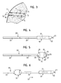
- Fig. 1 shows a landfill 1, which includes a pit 2, is poured into the garbage to a garbage mountain 3. At the bottom of the pit 2, a sealing layer 4 made of plastic, asphalt or other sealing material is provided by the contamination of the groundwater is avoided with hazardous substances.
- an approximately 2 m thick clay layer 5 is provided, which is covered with a film 6.
- the clay layer 5 and the film 6 also serve to seal the refuse dump.
- methane gas is formed over the years, which accumulates, for example, in approximately horizontally extending layers, as shown in FIG. 1 using the example of a methane gas layer 7.
- Fig. 1 an inventively designed drill 9 is further shown, with which a tube 10 is introduced into a slightly obliquely downwardly extending blind hole 11 in the landfill 1.
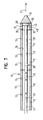
- the tube 10 consists of a plurality of butt welded together pipe sections 12, which are made of plastic, in particular PE. The detailed structure of the tube 10 will be described below with reference to FIG. 7.
- the tube 10 is arranged substantially over its entire length within the methane gas layer 7.
- Slit-shaped openings 13 are formed on the surface of the tube 10 (see FIG. 2), so that the methane gas present in the methane gas layer 7 can be sucked through the openings 13 into the tube 10, as indicated by arrows 14 in FIG ,
- the annular space in the region of the outlet opening 17 of the blind bore 11, which is formed between the outside of the tube 10 and the inner wall of the blind bore 11, is sealed with sealing material 18 .
- the seal prevents, on the one hand, that methane gas can escape uncontrollably via the outlet opening 17 into the environment and, on the other hand, a supply of ambient air via the outlet opening 17 into the annular space and subsequently via the openings 13 into the interior of the tube is prevented would lead to a mixing of ambient air with methane gas. In this way it is ensured that the extracted methane gas has a high degree of purity (for example 50-60%).
- a sealing material can be used, for example, a special damper in the annular space, for example. is introduced via an injection lance.
- a drill head 19 is shown, which is bolted via socketless screw with a drill rod 20.
- the drill rod 20 is screwed at its free end with a further drill rod 20 and forms together with this and further drill rods 20, a drill pipe (20 '), which has a substantially smooth surface due to the sleeveless screwing of the individual drill rods (20).
- a probe 21 is provided, with which the direction, the position, the distance and the respective angle to the earth's surface can be transmitted to a measuring device provided on the surface.
- a measuring device provided on the surface.
- an inclined control surface 22 is formed, via which a control of the drill head 19 is possible.
- one or more teeth 23 are formed at the tip of the drill head 19, through which the desired cutting action of the drill head 19 is achieved.
- Fig. 5 shows an inventively designed blind hole reamer 24, which, like the drill head 19, is bolted to boring bars 20.
- the blind hole reamer 24 has both at its front and at its back each have a conical, tapered shape, wherein the conical shape forming inclined surfaces 25, 26 have substantially the same angle with respect to the longitudinal axis of the drill rods 20 and the reamer 24 , Both in the region of the conical inclined surfaces 25, 26 and at the free front tip 27 of the blind hole reamer 24 respectively teeth 28 are formed through which the clearing action of the blind hole reamer 24 is increased.
- the incisors 28 are mounted so that there is no protrusion to the central part of the blind hole reamer 24 out.
- the central part of the blind hole reamer 24 has a cylindrical shape with a smooth surface in order to be able to produce the smoothest possible bore channel wall when retracting the blind hole reamer 24.
- Fig. 6 shows a combination of a drill head 19 with an inventively designed blind hole reamer 24.
- the drill head 19 and the Blind hole reamer 24 are connected to each other via a drill rod 20, wherein the blind hole reamer 24 is disposed in the drilling direction shown by an arrow 29 behind the drill head 19.
- a boring bar 20 is also screwed, which together with a plurality of further boring bars 20 completes the drill string 20 '.
- a terminating element 30 is provided at the front end of the tube 10.
- the closing element 30 may be formed from the same material as the tube 10 and be connected thereto by butt welding.
- the front end of the end element 30 forms a conical tip 31 consisting of solid material.
- a cavity 32 adjoins the tip 31 and may in particular have a circular cross-section and preferably has the same diameter as the interior 33 of the tube 10 that the inner sides 34 and 35 of the tube 10 and of the closing element 30 merge into one another continuously.
- a steel plate 36 is pressed into the cavity 32 in such a way that it rests substantially over the entire area on the tip 31 consisting of solid material and its surface 37 facing the cavity 32 extends transversely to the longitudinal axis of the tube 10.
- the steel plate 36 forms a reinforced portion of the tube 10.
- the reinforced portion may also be formed by another member suitable for reinforcement.
- a drive rod 38 is arranged, which according to an arrow 39 under high pressure against the surface 37th the metal plate 36 is pressed or repeatedly hit according to an arrow 40, for example via a pneumatic impact device on the surface 37 of the metal plate 36, so that the tube 10 is driven according to an arrow 41 to the front.
- the surface 37 thus forms a pressure or impact surface of the closure element 30.
- the drive rod 38 may consist of a plurality of drive rod sections 42, which are bolted together, for example, without a sleeve.
- the drive rod sections 42 may be formed by boring bars.
- a flat cover 43 is attached, via which the movement of the drive rod 38 is transferred to the metal plate 36 surface, so that a cutting of the leading edges of the drive rod 38, in particular when formed as a tubular drive rod 38th , is avoided.
- the drill head 19 is screwed onto the free end of a drill rod 20 and driven over the drill 9 in the landfill 1 to produce the blind hole drilling channel 11.
- the position and desired direction of the drill head 19 is determined via the signals emitted by the probe 21 in a known manner.
- the rotation of the drill head 19 is stopped and the drill string 20 'pushed forward without rotation, so that via the inclined control surface 22, the desired direction of the bore is readjusted.
- the drill head 19 may, for example, a Have outer diameter of 150mm. Depending on the application, larger or smaller diameters are possible.
- the drill pipe 20 is successively extended by screwing further drill rods 20 until the blind hole drilling channel 11 has reached its desired length.
- the individual drill rods can for example have a length of about 3m and a diameter of about 63mm. The lengths and diameters are to be selected depending on the application.
- the drill pipe 20 is pulled back out of the blind hole drill channel 11 via the drill 9, wherein one drill rod 20 is unscrewed after the other, until finally the drill head 19 is pulled out of the outlet opening 17 of the blind hole drilling channel 11.
- the blind hole reamer 24 is screwed onto a drill rod 20 and introduced via the drill 9 into the already existing blind hole drill channel 11 in order to widen it to its desired final width. Due to the tapered inclined surfaces 25 of the blind hole reamer 24 finds its way through the previously drilled blind hole drill channel 11, which is supported by the teeth 28, the expansion of the blind hole drilling channel 11.
- the blind hole reamer 24 may for example have an outer diameter of about 110mm, but depending on the application, larger or smaller diameter are possible.
- the drill string is on the drill 9 back out of the Pulled blind hole drill channel 11, wherein the individual drill rods 20 are screwed one after another again apart.
- the retraction of the blind hole reamer 24 is possible without problems, with any obstacles protruding into the blind hole bore channel 11 being removed by the teeth 28.
- the tube 10 is introduced into the now completely expanded blind hole drilling channel 11 in a next method step.
- first the end element 30 is connected to a first pipe section 12 by butt welding. It is important to ensure that the cooling times of the welded joint are maintained. Only then is it possible to drive in the pipes properly without damaging the weld joint.
- This first pipe section 12 is inserted together with the closing element 30 into the outlet opening 17 of the blind hole drilling channel 11.
- the drive rod 38 is inserted into the pipe section 12 until the drive rod 38 comes with its cover 43 on the surface 37 of the metal plate 36 to the plant.
- the drive rod 38 is pushed at its outwardly projecting out of the pipe section 12 end of the drill 9 at high pressure to the front, so that the pipe section 12 is inserted into the blind hole 11.
- the individual pipe sections 12 may for example have a length of about 3m and an outer diameter of about 110mm and an inner diameter of about 90mm. The lengths and diameters are to be selected according to the circumstances.
- a plurality of openings 38 is introduced depending on the application in the wall of the pipe section 12.
- this opening can be produced by cuts extending transversely to the longitudinal axis of the pipe section 12 in the wall of the pipe section 12.
- the number, size, shape and position of the openings can be adapted to the local needs.
- both the tube 10 and the drive rod 38 are each extended by respective addition of further pipe sections 12 and further drive rod sections 42, so that the tube 10 is driven further and further into the blind hole drilling channel 11, until it is completely in this lie comes.
- the outlet opening 17 is sealed in the area around the outwardly projecting tube 10 with sealing material 18, so that leakage of methane gas from the outlet opening 17 and entry of ambient atmosphere through the outlet opening 17 in the blind hole drilling channel 11 is excluded.
- the outward end of the tube 10 is connected in a conventional manner to a transport line 15, so that, for example, via a vacuum, the methane gas contained in the landfill can be sucked and fed to its further use.
- the described first and second process steps can be combined into a single process step.
- the blind hole 19 of the blind hole 19 is already widened to its desired width during the production of the pilot hole by the drill head 19 by means of the downstream reamer 24.
- the double-conical shape of the reamer 24 allows it to be easily driven or retracted both in the feed direction and in the retraction direction.
- the tube 10 is then introduced as described in the resulting blind hole drilling channel 11 in a further process step.
- This embodiment has the advantage that, on the one hand, a method step can be saved and, on the other hand, the reamer 24 can not be misdirected during its insertion due to its connection to the drill head 19. Due to the uneven consistency within the landfill 1, it is conceivable that even when produced by the drill head 19 blind hole drill 11 of the subsequently introduced reamer 24 deviates from its correct drilling line through the blind hole drill channel 11 and penetrates, for example, in a random side channel. This is precluded by the combination of drill head 19 with reamer 24 of FIG.
- drill head 19 alone to be used alone as described for producing the blind hole drilling channel 11, but that subsequently the combination of drill head 19 and blind hole reamer 24 shown in FIG. Drilling channel 11 is introduced to This way, via the probe 21 to check the correct insertion of the reamer 24 in the existing blind hole drilling channel 11.
Landscapes
- Engineering & Computer Science (AREA)
- Life Sciences & Earth Sciences (AREA)
- Geology (AREA)
- Mining & Mineral Resources (AREA)
- Environmental & Geological Engineering (AREA)
- Physics & Mathematics (AREA)
- Fluid Mechanics (AREA)
- General Life Sciences & Earth Sciences (AREA)
- Geochemistry & Mineralogy (AREA)
- Earth Drilling (AREA)
Priority Applications (1)
| Application Number | Priority Date | Filing Date | Title |
|---|---|---|---|
| EP05022828.7A EP1785580B1 (fr) | 2005-10-19 | 2005-10-19 | Procédé pour poser de tuyaux, élargisseur, dispositif de forage et tuyau |
Applications Claiming Priority (1)
| Application Number | Priority Date | Filing Date | Title |
|---|---|---|---|
| EP05022828.7A EP1785580B1 (fr) | 2005-10-19 | 2005-10-19 | Procédé pour poser de tuyaux, élargisseur, dispositif de forage et tuyau |
Publications (2)
| Publication Number | Publication Date |
|---|---|
| EP1785580A1 true EP1785580A1 (fr) | 2007-05-16 |
| EP1785580B1 EP1785580B1 (fr) | 2021-01-06 |
Family
ID=36061633
Family Applications (1)
| Application Number | Title | Priority Date | Filing Date |
|---|---|---|---|
| EP05022828.7A Expired - Lifetime EP1785580B1 (fr) | 2005-10-19 | 2005-10-19 | Procédé pour poser de tuyaux, élargisseur, dispositif de forage et tuyau |
Country Status (1)
| Country | Link |
|---|---|
| EP (1) | EP1785580B1 (fr) |
Cited By (2)
| Publication number | Priority date | Publication date | Assignee | Title |
|---|---|---|---|---|
| NL1036270C2 (nl) * | 2008-12-03 | 2010-06-07 | Trisoplast Int Bv | Werkwijze voor het stimuleren van biologische afbraak en het ontgassen van vuilnisstortplaatsen. |
| CN115710962A (zh) * | 2022-10-24 | 2023-02-24 | 上田环境修复有限公司 | 一种垃圾填埋场水平井结构的施工方法 |
Citations (7)
| Publication number | Priority date | Publication date | Assignee | Title |
|---|---|---|---|---|
| DE3109120A1 (de) * | 1981-03-11 | 1982-09-23 | Heinz Dr.-Ing. 4300 Essen Steffen | "verfahren und anlage zur gewinnung von methanhaltigem brenngas aus einer muelldeponie" |
| US4483396A (en) * | 1983-06-24 | 1984-11-20 | Kennelly James R | Landfill gas well |
| EP0299624A2 (fr) * | 1987-07-13 | 1989-01-18 | Cherrington Corporation | Appareil et procédé pour installer un conduit dans un puits courbe |
| EP0505218A1 (fr) * | 1991-03-22 | 1992-09-23 | Westpile Limited | Améliorations relatives au dégazage de dépôts de déchets et au contrôle des eaux d'infiltration |
| US20040159468A1 (en) * | 2001-08-08 | 2004-08-19 | Hoffmaster Carl M. | Advanced expandable reaming tool |
| US20050111918A1 (en) * | 2003-10-21 | 2005-05-26 | Bentley Development Co., Inc. | Landfill gas recovery system |
| US6926100B1 (en) * | 2002-03-12 | 2005-08-09 | Xtech Industries International, Inc. | Hole reaming apparatus and method |
Family Cites Families (3)
| Publication number | Priority date | Publication date | Assignee | Title |
|---|---|---|---|---|
| US6386302B1 (en) * | 1999-09-09 | 2002-05-14 | Smith International, Inc. | Polycrystaline diamond compact insert reaming tool |
| US6732817B2 (en) * | 2002-02-19 | 2004-05-11 | Smith International, Inc. | Expandable underreamer/stabilizer |
| GB2412388B (en) * | 2004-03-27 | 2006-09-27 | Schlumberger Holdings | Bottom hole assembly |
-
2005
- 2005-10-19 EP EP05022828.7A patent/EP1785580B1/fr not_active Expired - Lifetime
Patent Citations (7)
| Publication number | Priority date | Publication date | Assignee | Title |
|---|---|---|---|---|
| DE3109120A1 (de) * | 1981-03-11 | 1982-09-23 | Heinz Dr.-Ing. 4300 Essen Steffen | "verfahren und anlage zur gewinnung von methanhaltigem brenngas aus einer muelldeponie" |
| US4483396A (en) * | 1983-06-24 | 1984-11-20 | Kennelly James R | Landfill gas well |
| EP0299624A2 (fr) * | 1987-07-13 | 1989-01-18 | Cherrington Corporation | Appareil et procédé pour installer un conduit dans un puits courbe |
| EP0505218A1 (fr) * | 1991-03-22 | 1992-09-23 | Westpile Limited | Améliorations relatives au dégazage de dépôts de déchets et au contrôle des eaux d'infiltration |
| US20040159468A1 (en) * | 2001-08-08 | 2004-08-19 | Hoffmaster Carl M. | Advanced expandable reaming tool |
| US6926100B1 (en) * | 2002-03-12 | 2005-08-09 | Xtech Industries International, Inc. | Hole reaming apparatus and method |
| US20050111918A1 (en) * | 2003-10-21 | 2005-05-26 | Bentley Development Co., Inc. | Landfill gas recovery system |
Cited By (4)
| Publication number | Priority date | Publication date | Assignee | Title |
|---|---|---|---|---|
| NL1036270C2 (nl) * | 2008-12-03 | 2010-06-07 | Trisoplast Int Bv | Werkwijze voor het stimuleren van biologische afbraak en het ontgassen van vuilnisstortplaatsen. |
| WO2010068087A1 (fr) * | 2008-12-03 | 2010-06-17 | Trisoplast International B.V. | Procédé pour activer la biodégradation et le dégazage de sites de d'élimination de déchets |
| EA027813B1 (ru) * | 2008-12-03 | 2017-09-29 | Трисопласт Интернэшнл Б.В. | Способ стимулирования биологического разложения и дегазации площадок для переработки отходов |
| CN115710962A (zh) * | 2022-10-24 | 2023-02-24 | 上田环境修复有限公司 | 一种垃圾填埋场水平井结构的施工方法 |
Also Published As
| Publication number | Publication date |
|---|---|
| EP1785580B1 (fr) | 2021-01-06 |
Similar Documents
| Publication | Publication Date | Title |
|---|---|---|
| DE102007002399B4 (de) | Verfahren und Vorrichtung zur Herstellung einer verrohrten Strangbohrung | |
| DE102013111350A1 (de) | Aufweitwerkzeug und Vorrichtung zum Aufweiten einer im Erdreich vorhandenen Durchgangsöffnung | |
| WO2009115307A1 (fr) | Cheville autoforeuse protégée contre la corrosion, et bloc d'éléments de cheville, et leur procédé de fabrication | |
| EP0293584B1 (fr) | Dispositif de forage pour méthode de forage par injection à haute pression | |
| CH683016A5 (de) | Verfahren zum Aufweiten eines Bohrloches und Aufweitgerät. | |
| DE1533644C3 (de) | Verfahren und Vorrichtung zum annähernd waagerechten Durchbohren von Dämmen aus Erd- oder Gesteinsschichten | |
| DE3624202C2 (de) | Spiralbohrer | |
| DE3801824C1 (en) | Method and apparatus for the trenchless laying of supply lines | |
| DE19749007C2 (de) | Vorrichtung zum Verbinden eines Nachziehrohres mit einem Ziehgerät | |
| EP1785580B1 (fr) | Procédé pour poser de tuyaux, élargisseur, dispositif de forage et tuyau | |
| DE102014004087B3 (de) | Selbstbohrende Injektionslanze und Verfahren zur Erdreichstabilisierung unter Verwendung derselben | |
| EP0159573B1 (fr) | Procédé et dispositif pour la pose des conduites souterraines d'intérieur inaccessible par poussage contrôlé | |
| EP3091173A1 (fr) | Installation de forage destinee a produire ou a elargir un forage terrestre dans la terre et procede de commande d'un dispositif d'avance d'une telle installation de forage | |
| DE3926787C2 (de) | Verfahren und Vorrichtung zum Einbringen und Verankern eines Zugpfahls | |
| DE2250635A1 (de) | Verfahren zum bau eines tunnels | |
| DE3728270A1 (de) | Verfahren und vorrichtung zur herstellung von betonpfaehlen im boden | |
| DE102007015088B4 (de) | Verfahren zum mehrstufigen Herstellen einer Erdbohrung und Vorrichtung zur Durchführung des Verfahrens | |
| DE102020127156B4 (de) | Vorrichtung zum Bohren einer horizontalen Bohrung | |
| EP4368809B1 (fr) | Dispositif de rinçage, notamment pour l'installation dans un train de tiges de forage | |
| DE10319800A1 (de) | Hohlbohrkrone für Kernbohrmaschinen | |
| DE19729882C1 (de) | Verfahren und Vorrichtung zum Herstellen eines Bohrpfahls | |
| EP3663504B1 (fr) | Procédé de terrassement, dispositif de terrassement et installation de terrassement | |
| EP3530871B1 (fr) | Dispositif de production ou d'élargissement d'un forage de sol | |
| DE10114625A1 (de) | Vorrichtung, Verfahren und Verlegeeinrichtung zur hydraulischen Stützung eines Tunnels | |
| WO2025252351A1 (fr) | Agencement et dispositif de forage et procédé de formation d'une colonne de matériau de remplissage dans le sol |
Legal Events
| Date | Code | Title | Description |
|---|---|---|---|
| PUAI | Public reference made under article 153(3) epc to a published international application that has entered the european phase |
Free format text: ORIGINAL CODE: 0009012 |
|
| AK | Designated contracting states |
Kind code of ref document: A1 Designated state(s): AT BE BG CH CY CZ DE DK EE ES FI FR GB GR HU IE IS IT LI LT LU LV MC NL PL PT RO SE SI SK TR |
|
| AX | Request for extension of the european patent |
Extension state: AL BA HR MK YU |
|
| 17P | Request for examination filed |
Effective date: 20071022 |
|
| 17Q | First examination report despatched |
Effective date: 20071213 |
|
| AKX | Designation fees paid |
Designated state(s): AT BE BG CH CY CZ DE DK EE ES FI FR GB GR HU IE IS IT LI LT LU LV MC NL PL PT RO SE SI SK TR |
|
| AXX | Extension fees paid |
Extension state: YU Payment date: 20071022 Extension state: MK Payment date: 20071022 Extension state: HR Payment date: 20071022 Extension state: BA Payment date: 20071022 Extension state: AL Payment date: 20071022 |
|
| STAA | Information on the status of an ep patent application or granted ep patent |
Free format text: STATUS: EXAMINATION IS IN PROGRESS |
|
| GRAP | Despatch of communication of intention to grant a patent |
Free format text: ORIGINAL CODE: EPIDOSNIGR1 |
|
| STAA | Information on the status of an ep patent application or granted ep patent |
Free format text: STATUS: GRANT OF PATENT IS INTENDED |
|
| INTG | Intention to grant announced |
Effective date: 20200720 |
|
| RIN1 | Information on inventor provided before grant (corrected) |
Inventor name: RIEDL, ROLAND Inventor name: KOLLER, MANFRED |
|
| GRAS | Grant fee paid |
Free format text: ORIGINAL CODE: EPIDOSNIGR3 |
|
| GRAA | (expected) grant |
Free format text: ORIGINAL CODE: 0009210 |
|
| STAA | Information on the status of an ep patent application or granted ep patent |
Free format text: STATUS: THE PATENT HAS BEEN GRANTED |
|
| REG | Reference to a national code |
Ref country code: DE Ref legal event code: R081 Ref document number: 502005016171 Country of ref document: DE Owner name: MAX STREICHER GMBH & CO. KOMMANDITGESELLSCHAFT, DE Free format text: FORMER OWNER: MAX STREICHER GMBH & CO. KGAA, 94469 DEGGENDORF, DE |
|
| AK | Designated contracting states |
Kind code of ref document: B1 Designated state(s): AT BE BG CH CY CZ DE DK EE ES FI FR GB GR HU IE IS IT LI LT LU LV MC NL PL PT RO SE SI SK TR |
|
| AX | Request for extension of the european patent |
Extension state: AL BA HR MK YU |
|
| REG | Reference to a national code |
Ref country code: GB Ref legal event code: FG4D Free format text: NOT ENGLISH |
|
| REG | Reference to a national code |
Ref country code: AT Ref legal event code: REF Ref document number: 1352563 Country of ref document: AT Kind code of ref document: T Effective date: 20210115 Ref country code: CH Ref legal event code: EP |
|
| REG | Reference to a national code |
Ref country code: DE Ref legal event code: R096 Ref document number: 502005016171 Country of ref document: DE |
|
| REG | Reference to a national code |
Ref country code: IE Ref legal event code: FG4D Free format text: LANGUAGE OF EP DOCUMENT: GERMAN |
|
| REG | Reference to a national code |
Ref country code: NL Ref legal event code: MP Effective date: 20210106 |
|
| REG | Reference to a national code |
Ref country code: LT Ref legal event code: MG9D |
|
| PG25 | Lapsed in a contracting state [announced via postgrant information from national office to epo] |
Ref country code: LT Free format text: LAPSE BECAUSE OF FAILURE TO SUBMIT A TRANSLATION OF THE DESCRIPTION OR TO PAY THE FEE WITHIN THE PRESCRIBED TIME-LIMIT Effective date: 20210106 Ref country code: FI Free format text: LAPSE BECAUSE OF FAILURE TO SUBMIT A TRANSLATION OF THE DESCRIPTION OR TO PAY THE FEE WITHIN THE PRESCRIBED TIME-LIMIT Effective date: 20210106 Ref country code: GR Free format text: LAPSE BECAUSE OF FAILURE TO SUBMIT A TRANSLATION OF THE DESCRIPTION OR TO PAY THE FEE WITHIN THE PRESCRIBED TIME-LIMIT Effective date: 20210407 Ref country code: PT Free format text: LAPSE BECAUSE OF FAILURE TO SUBMIT A TRANSLATION OF THE DESCRIPTION OR TO PAY THE FEE WITHIN THE PRESCRIBED TIME-LIMIT Effective date: 20210506 Ref country code: BG Free format text: LAPSE BECAUSE OF FAILURE TO SUBMIT A TRANSLATION OF THE DESCRIPTION OR TO PAY THE FEE WITHIN THE PRESCRIBED TIME-LIMIT Effective date: 20210406 Ref country code: NL Free format text: LAPSE BECAUSE OF FAILURE TO SUBMIT A TRANSLATION OF THE DESCRIPTION OR TO PAY THE FEE WITHIN THE PRESCRIBED TIME-LIMIT Effective date: 20210106 |
|
| PG25 | Lapsed in a contracting state [announced via postgrant information from national office to epo] |
Ref country code: SE Free format text: LAPSE BECAUSE OF FAILURE TO SUBMIT A TRANSLATION OF THE DESCRIPTION OR TO PAY THE FEE WITHIN THE PRESCRIBED TIME-LIMIT Effective date: 20210106 Ref country code: LV Free format text: LAPSE BECAUSE OF FAILURE TO SUBMIT A TRANSLATION OF THE DESCRIPTION OR TO PAY THE FEE WITHIN THE PRESCRIBED TIME-LIMIT Effective date: 20210106 Ref country code: PL Free format text: LAPSE BECAUSE OF FAILURE TO SUBMIT A TRANSLATION OF THE DESCRIPTION OR TO PAY THE FEE WITHIN THE PRESCRIBED TIME-LIMIT Effective date: 20210106 |
|
| PG25 | Lapsed in a contracting state [announced via postgrant information from national office to epo] |
Ref country code: IS Free format text: LAPSE BECAUSE OF FAILURE TO SUBMIT A TRANSLATION OF THE DESCRIPTION OR TO PAY THE FEE WITHIN THE PRESCRIBED TIME-LIMIT Effective date: 20210506 |
|
| REG | Reference to a national code |
Ref country code: DE Ref legal event code: R097 Ref document number: 502005016171 Country of ref document: DE |
|
| PG25 | Lapsed in a contracting state [announced via postgrant information from national office to epo] |
Ref country code: CZ Free format text: LAPSE BECAUSE OF FAILURE TO SUBMIT A TRANSLATION OF THE DESCRIPTION OR TO PAY THE FEE WITHIN THE PRESCRIBED TIME-LIMIT Effective date: 20210106 Ref country code: EE Free format text: LAPSE BECAUSE OF FAILURE TO SUBMIT A TRANSLATION OF THE DESCRIPTION OR TO PAY THE FEE WITHIN THE PRESCRIBED TIME-LIMIT Effective date: 20210106 |
|
| PLBE | No opposition filed within time limit |
Free format text: ORIGINAL CODE: 0009261 |
|
| STAA | Information on the status of an ep patent application or granted ep patent |
Free format text: STATUS: NO OPPOSITION FILED WITHIN TIME LIMIT |
|
| PG25 | Lapsed in a contracting state [announced via postgrant information from national office to epo] |
Ref country code: SK Free format text: LAPSE BECAUSE OF FAILURE TO SUBMIT A TRANSLATION OF THE DESCRIPTION OR TO PAY THE FEE WITHIN THE PRESCRIBED TIME-LIMIT Effective date: 20210106 Ref country code: ES Free format text: LAPSE BECAUSE OF FAILURE TO SUBMIT A TRANSLATION OF THE DESCRIPTION OR TO PAY THE FEE WITHIN THE PRESCRIBED TIME-LIMIT Effective date: 20210106 Ref country code: DK Free format text: LAPSE BECAUSE OF FAILURE TO SUBMIT A TRANSLATION OF THE DESCRIPTION OR TO PAY THE FEE WITHIN THE PRESCRIBED TIME-LIMIT Effective date: 20210106 Ref country code: RO Free format text: LAPSE BECAUSE OF FAILURE TO SUBMIT A TRANSLATION OF THE DESCRIPTION OR TO PAY THE FEE WITHIN THE PRESCRIBED TIME-LIMIT Effective date: 20210106 |
|
| 26N | No opposition filed |
Effective date: 20211007 |
|
| PG25 | Lapsed in a contracting state [announced via postgrant information from national office to epo] |
Ref country code: SI Free format text: LAPSE BECAUSE OF FAILURE TO SUBMIT A TRANSLATION OF THE DESCRIPTION OR TO PAY THE FEE WITHIN THE PRESCRIBED TIME-LIMIT Effective date: 20210106 |
|
| PG25 | Lapsed in a contracting state [announced via postgrant information from national office to epo] |
Ref country code: IT Free format text: LAPSE BECAUSE OF FAILURE TO SUBMIT A TRANSLATION OF THE DESCRIPTION OR TO PAY THE FEE WITHIN THE PRESCRIBED TIME-LIMIT Effective date: 20210106 |
|
| REG | Reference to a national code |
Ref country code: CH Ref legal event code: PL |
|
| PG25 | Lapsed in a contracting state [announced via postgrant information from national office to epo] |
Ref country code: IS Free format text: LAPSE BECAUSE OF FAILURE TO SUBMIT A TRANSLATION OF THE DESCRIPTION OR TO PAY THE FEE WITHIN THE PRESCRIBED TIME-LIMIT Effective date: 20210506 |
|
| REG | Reference to a national code |
Ref country code: BE Ref legal event code: MM Effective date: 20211031 |
|
| GBPC | Gb: european patent ceased through non-payment of renewal fee |
Effective date: 20211019 |
|
| PG25 | Lapsed in a contracting state [announced via postgrant information from national office to epo] |
Ref country code: MC Free format text: LAPSE BECAUSE OF FAILURE TO SUBMIT A TRANSLATION OF THE DESCRIPTION OR TO PAY THE FEE WITHIN THE PRESCRIBED TIME-LIMIT Effective date: 20210106 |
|
| PG25 | Lapsed in a contracting state [announced via postgrant information from national office to epo] |
Ref country code: LU Free format text: LAPSE BECAUSE OF NON-PAYMENT OF DUE FEES Effective date: 20211019 Ref country code: GB Free format text: LAPSE BECAUSE OF NON-PAYMENT OF DUE FEES Effective date: 20211019 Ref country code: BE Free format text: LAPSE BECAUSE OF NON-PAYMENT OF DUE FEES Effective date: 20211031 |
|
| PG25 | Lapsed in a contracting state [announced via postgrant information from national office to epo] |
Ref country code: LI Free format text: LAPSE BECAUSE OF NON-PAYMENT OF DUE FEES Effective date: 20211031 Ref country code: CH Free format text: LAPSE BECAUSE OF NON-PAYMENT OF DUE FEES Effective date: 20211031 |
|
| PG25 | Lapsed in a contracting state [announced via postgrant information from national office to epo] |
Ref country code: FR Free format text: LAPSE BECAUSE OF NON-PAYMENT OF DUE FEES Effective date: 20211031 |
|
| PG25 | Lapsed in a contracting state [announced via postgrant information from national office to epo] |
Ref country code: IE Free format text: LAPSE BECAUSE OF NON-PAYMENT OF DUE FEES Effective date: 20211019 |
|
| REG | Reference to a national code |
Ref country code: AT Ref legal event code: MM01 Ref document number: 1352563 Country of ref document: AT Kind code of ref document: T Effective date: 20211019 |
|
| PG25 | Lapsed in a contracting state [announced via postgrant information from national office to epo] |
Ref country code: AT Free format text: LAPSE BECAUSE OF NON-PAYMENT OF DUE FEES Effective date: 20211019 |
|
| PG25 | Lapsed in a contracting state [announced via postgrant information from national office to epo] |
Ref country code: HU Free format text: LAPSE BECAUSE OF FAILURE TO SUBMIT A TRANSLATION OF THE DESCRIPTION OR TO PAY THE FEE WITHIN THE PRESCRIBED TIME-LIMIT; INVALID AB INITIO Effective date: 20051019 Ref country code: CY Free format text: LAPSE BECAUSE OF FAILURE TO SUBMIT A TRANSLATION OF THE DESCRIPTION OR TO PAY THE FEE WITHIN THE PRESCRIBED TIME-LIMIT Effective date: 20210106 |
|
| PGFP | Annual fee paid to national office [announced via postgrant information from national office to epo] |
Ref country code: DE Payment date: 20241223 Year of fee payment: 20 |
|
| REG | Reference to a national code |
Ref country code: DE Ref legal event code: R071 Ref document number: 502005016171 Country of ref document: DE |
|
| PG25 | Lapsed in a contracting state [announced via postgrant information from national office to epo] |
Ref country code: TR Free format text: LAPSE BECAUSE OF FAILURE TO SUBMIT A TRANSLATION OF THE DESCRIPTION OR TO PAY THE FEE WITHIN THE PRESCRIBED TIME-LIMIT Effective date: 20210106 |