EP1788350A2 - Dispositif de mesure à laser - Google Patents
Dispositif de mesure à laser Download PDFInfo
- Publication number
- EP1788350A2 EP1788350A2 EP06023615A EP06023615A EP1788350A2 EP 1788350 A2 EP1788350 A2 EP 1788350A2 EP 06023615 A EP06023615 A EP 06023615A EP 06023615 A EP06023615 A EP 06023615A EP 1788350 A2 EP1788350 A2 EP 1788350A2
- Authority
- EP
- European Patent Office
- Prior art keywords
- laser
- measuring device
- housing
- laser measuring
- alignment surface
- Prior art date
- Legal status (The legal status is an assumption and is not a legal conclusion. Google has not performed a legal analysis and makes no representation as to the accuracy of the status listed.)
- Granted
Links
- 229910000679 solder Inorganic materials 0.000 claims description 18
- 230000001360 synchronised effect Effects 0.000 claims description 4
- 238000010276 construction Methods 0.000 description 1
- 230000008878 coupling Effects 0.000 description 1
- 238000010168 coupling process Methods 0.000 description 1
- 238000005859 coupling reaction Methods 0.000 description 1
- 238000006073 displacement reaction Methods 0.000 description 1
- 230000000694 effects Effects 0.000 description 1
- 238000003384 imaging method Methods 0.000 description 1
- 230000036316 preload Effects 0.000 description 1
- 238000005476 soldering Methods 0.000 description 1
Images

Classifications
-
- G—PHYSICS
- G01—MEASURING; TESTING
- G01C—MEASURING DISTANCES, LEVELS OR BEARINGS; SURVEYING; NAVIGATION; GYROSCOPIC INSTRUMENTS; PHOTOGRAMMETRY OR VIDEOGRAMMETRY
- G01C15/00—Surveying instruments or accessories not provided for in groups G01C1/00 - G01C13/00
- G01C15/10—Plumb lines
Definitions
- the invention relates to a laser measuring device comprising a housing with in this existing laser device for generating and projecting at least one laser beam perpendicular to an alignment surface of the housing or an alignment surface of a mount connectable to the housing.
- a laser measuring device can be generated by the four perpendicular laser beams, which are used for soldering and leveling.
- the laser beam generating laser device which includes the laser light source and optics, suspended pendulum to achieve a self-centering of the solder beam.
- Corresponding laser measuring devices can also have a wall mount, for example, connected to the housing of the laser measuring device via magnets in order to be able to use the measuring device independently of a tripod or another stand surface.
- the wall mount can also be aligned to the housing so that the former serves as a receptacle for a tripod.
- Corresponding laser measuring devices should also offer the possibility of imaging a marking perpendicular to an opening in the floor area of a room in its ceiling area in order, for example, to arrange a riser pipe which runs between the openings. In this case, difficulties often arise because the alignment of the solder beam in the direction of the ceiling is then not sufficiently accurate when the extension of the solder beam or an antiparallel to the solder beam extending further laser beam does not pass through the opening in the middle.
- the DE-A-33 17 732 refers to a geodetic instrument with a tripod, whose feet are axially adjustable.
- a gyrocompass after the DE-A-31 18 822 has about horizontal axis pivotable tripod feet, which in turn are extendable.
- the present invention has the object, a laser measuring device of the type described above educate so that a very precise alignment of a laser beam to the center of an opening in a space boundary such as ground is possible without the need for complicated adjustments.
- the invention essentially provides that the alignment surface are assigned at least three synchronously adjustable positioning, which lie on a circle, the center of which is penetrated by the laser beam or its extension.
- each positioning means or element comprises in particular an arm which is pivotable about an axis extending perpendicular to the alignment surface and has in its free end region a directed away from the alignment surface projecting projection.
- the projection may have a cylindrical shape whose longitudinal axis is parallel to the pivot axis of the arm.
- the positioning means or elements can also have adjustable supports along grooves or link slots, which can be adjusted via a driver element are, which in turn z. B. via eccentric cams or eccentrically extending grooves causes the synchronous radial displacement of the positioning.
- a self-centering of the housing and thus of the laser beam takes place via the positioning means or elements which can be aligned with an opening in such a way that the projections protrude into it, so that when they touch the inner wall of the opening, it will also be can act to a pipe, automatically the laser beam passes through the center of the opening.
- This is based on a proper construction, i. E. the surface which is penetrated by the opening is oriented to a sufficient extent to the horizontal, as a result of which a marking running precisely over the opening can be imaged by means of the laser beam on the opposite surface.
- a self-centering of the laser beam is made possible by purely mechanical means, so that erroneous alignments of the laser beam to an opening or other exit area are excluded by a user operating the laser measuring device.
- the positioning means or elements which can also be referred to as feet, can be adjusted synchronously and in a coupled manner, wherein provision is made in particular for a gear which surrounds the pivot axis to extend concentrically from each arm and which meshes with a central toothed wheel. This can then be adjusted, for example, via a knurled nut such that the projections projecting from the arms rest on the inner surface of the opening and are thus positioned on a circle whose center coincides with the center of the opening.
- the alignment surface penetrates one of the laser beam or a second laser beam extending in its extension Opening has, to which runs coaxially the circle on which the positioning means and their projections lie.
- circle includes circles of different diameters depending on the orientation of the diameter of the opening, all circles have the same center.
- the alignment surface is, for example, the bottom surface of the housing, then this may preferably also be the outer surface of the holder connected to the housing.
- the alignment surface of the holder runs parallel to the bottom surface of the housing.
- the arranged in the housing laser device itself is self-centering and arranged in particular oscillating. Furthermore, the laser beam generated by the laser light source can be divided into four mutually perpendicular partial beams, two of which are anti-parallel to each other and perpendicular.
- the existing in the alignment surface opening preferably serves simultaneously as a receptacle for a tripod. Regardless of this, the aperture may be penetrated by the further laser beam extending antiparallel to the laser beam directed away from the positioning means.
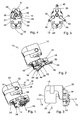
- FIGS. 1-5 a first embodiment of a laser measuring device 10 is shown purely in principle, which comprises a housing 12 which is releasably connected to a holder 14.
- the connection between the housing 12 and the holder 14 can be effected via magnets or other connecting means, without thereby limiting the invention.
- the housing 12 consists of a head portion 16 which is formed overhanging with respect to the foot part 18.
- the laser gauge 10, i. the housing 12 comprises a laser light source with optics, not shown, with which the laser beam generated by the laser light source is divided into four mutually perpendicular laser beams 13, 15, 17, 19 in order to solder and leveling.
- Two of the four beams are anti-parallel and in horizontal alignment of the bottom surface 20 of the housing 12 vertically, one of the solder jets 13, the top surface 22 of the housing 12 and the other solder jet 15, the bottom of the overhanging housing 12 and in dependence on the extension of the foot part 18th also its bottom surface 20 passes through.
- Another perpendicular to this extending laser beam 17 passes through a side wall 24 and the fourth laser beam 19, the end face 26 of the housing 12.
- positioning means are provided by an alignment surface of the housing 12 or the holder 14 which is perpendicular to the solder beam 15 emanating from the inner boundary of the openings, a self-centering of the solder beam 15 is given to the center of the opening and is thus mapped to the bottom surface opposite surface in vertical extension of a mark.
- the synchronous pivoting is preferably carried out by a forced coupling of the positioning.
- the teaching according to the invention for the vertical alignment of openings in a floor and a top wall of a room, the same applies to the horizontal aligned alignment of openings in vertically extending and mutually spaced walls.
- the laser beam is horizontal.
- the positioning means or elements are formed in the embodiment as feet 28, 30, 32 which are pivotable about axes 27, 29, 31, which are parallel to the solder beam 15th and thus perpendicular to the alignment surface, which in the embodiment outer surface 34 of the holder 14, which extends parallel to the bottom surface 20 of the housing 12 and its foot 18.
- the feet 28, 30, 32 consist of pivotable arms 36, 38, 40, protruding from which end projections 42, 44, 46, each having a cylindrical shape with a longitudinal axis which extend parallel to the pivot axes 27, 29, 30.
- the feet 28, 30, 32 and arms 36, 38, 40 are synchronously and forcibly coupled pivotable such that regardless of the pivot angle, the projections 42, 44, 46 are always on a circle, the circles of different diameters have the same center.
- This center point is aligned with the plumb beam 15 so as to penetrate the center point, provided that, when the pendulum device is suspended in pendulum fashion, the housing 12, i. whose bottom surface 20 or parallel to this alignment surface 34 is aligned horizontally. Accordingly, the plane spanned by the undersides of the arms 36, 38, 40 extends over which the projections 42, 44, 46 project, parallel to the alignment surface 34 and thus the bottom surface 30 of the housing 12.
- the pivot axes 27, 29, 31 of the arms 36, 38, 40 are located on a circle concentric with an opening 33, which can serve as a receptacle for a tripod on which the housing 12 and the holder 14 such as can be screwed if use according to the invention does not take place.
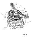
- the positively coupled movement ie the pivoting of the feet 28, 30, 32 takes place in particular by the fact that from each arm 36, 38, 40 a satellite gear 64, 66, 68 goes out (FIG. 8), coaxially the respective pivot axis 27, 29, 31 surrounds.
- the satellite gears 64, 66, 68 each of equal diameter then cooperate with a central gear 70, whereby the required for the realization of the invention, synchronous movement of the arms 36, 38, 40 is ensured.
- the central gear 70 can then be adjusted via an accessible from the outside of the holder 14 knurled nut 48 so as to align the projections 42, 44, 46 to an opening or the inside thereof.
- the teaching according to the invention is suitable for any laser measuring device with which a laser beam is generated which is perpendicular to the plane spanned by positioning means or elements. This will be clarified purely in principle with reference to FIGS. 6 and 7. Here, the same reference numerals as in connection with Figs. 1 - 4 are used for the same elements.
- a measuring device 50 in which a solder beam 54 is generated.
- a jet 52 extends antiparallel to the solder jet 54.
- This jet 52 and thus the solder jet 54 run perpendicular to the outer surface 34 of the mount 14 and thus to the plane defined by the free undersides of the pivotable arms 36, 38, 40 the in particular a cylindrical shape having projections 42, 44, 46 is surmounted.
- the housing 56 of the laser measuring device 50 is detachably connected to the holder 14. If a magnetic connection is provided in the exemplary embodiments according to FIGS. 1-4, the holder 14 of the laser measuring device 50 is provided with the Housing 12 mechanically via latching fingers 58, 60, 62 connected to illustrate purely by way of example a possibility of a connection.
- the center of the spanned by the positioning means or elements 28, 30, 32 circles runs according to the Fig. 1 - 4 within the aperture 33 in the holder 14.
- the aperture 33 is penetrated by the laser beam 54, which is in anti-parallel to the beam 52 extends, which starts from the top surface 22 of the housing 12.
Landscapes
- Physics & Mathematics (AREA)
- Engineering & Computer Science (AREA)
- General Physics & Mathematics (AREA)
- Radar, Positioning & Navigation (AREA)
- Remote Sensing (AREA)
- Length Measuring Devices By Optical Means (AREA)
- Photometry And Measurement Of Optical Pulse Characteristics (AREA)
- Conveying And Assembling Of Building Elements In Situ (AREA)
Applications Claiming Priority (1)
| Application Number | Priority Date | Filing Date | Title |
|---|---|---|---|
| DE202005018286U DE202005018286U1 (de) | 2005-11-21 | 2005-11-21 | Lasermessgerät |
Publications (3)
| Publication Number | Publication Date |
|---|---|
| EP1788350A2 true EP1788350A2 (fr) | 2007-05-23 |
| EP1788350A3 EP1788350A3 (fr) | 2009-08-12 |
| EP1788350B1 EP1788350B1 (fr) | 2012-01-04 |
Family
ID=37770938
Family Applications (1)
| Application Number | Title | Priority Date | Filing Date |
|---|---|---|---|
| EP06023615A Not-in-force EP1788350B1 (fr) | 2005-11-21 | 2006-11-14 | Dispositif de mesure à laser |
Country Status (4)
| Country | Link |
|---|---|
| US (1) | US7675612B2 (fr) |
| EP (1) | EP1788350B1 (fr) |
| CN (1) | CN1971214B (fr) |
| DE (1) | DE202005018286U1 (fr) |
Families Citing this family (19)
| Publication number | Priority date | Publication date | Assignee | Title |
|---|---|---|---|---|
| EP1855174A1 (fr) * | 2006-05-11 | 2007-11-14 | Leica Geosystems AG | Source de rayon laser pour guidage d'un véhicule à marquer |
| US7454839B2 (en) * | 2006-08-22 | 2008-11-25 | Robotoolz, Ltd. | Portable reference laser unit and attachment accessory |
| EP2698596A1 (fr) * | 2012-08-16 | 2014-02-19 | Hexagon Technology Center GmbH | Procédé et système permettant de déterminer les coordonnées spatiales avec une machine de mesure de coordonnées mobiles |
| CN107209013A (zh) | 2014-11-13 | 2017-09-26 | 米沃奇电动工具公司 | 包括可移除的端盖的水平仪 |
| US10119817B2 (en) | 2016-04-28 | 2018-11-06 | Stanley Black & Decker Inc. | Laser level |
| US10845193B2 (en) | 2016-12-21 | 2020-11-24 | Milwaukee Electric Tool Corporation | Level with removable end cap |
| CN110088570A (zh) | 2016-12-21 | 2019-08-02 | 米沃奇电动工具公司 | 具有可拆卸端盖的水平仪 |
| EP3421225A1 (fr) * | 2017-06-26 | 2019-01-02 | Raylase GmbH | Étalonnage automatisé d'un dispositif destiné à la fabrication additive entièrement parallélisée d'un composant à champs d'action combiné |
| WO2019210076A1 (fr) | 2018-04-27 | 2019-10-31 | Milwaukee Electric Tool Corporation | Niveau à capuchon d'extrémité amovible à élément de préhension de paroi |
| US11085762B2 (en) | 2018-04-27 | 2021-08-10 | Milwaukee Electric Tool Corporation | Level with removable end cap with wall grip |
| CN116625331A (zh) * | 2019-01-16 | 2023-08-22 | 米沃奇电动工具公司 | 激光投射装置和用于激光投射装置的框架 |
| US11385055B2 (en) | 2019-07-23 | 2022-07-12 | Milwaukee Electric Tool Corporation | Laser emitter with a modular storage unit |
| CN112066873A (zh) * | 2020-07-17 | 2020-12-11 | 沪东中华造船(集团)有限公司 | 一种船舶主机与齿轮箱的对中方法 |
| WO2022094408A1 (fr) * | 2020-11-02 | 2022-05-05 | Milwaukee Electric Tool Corporation | Outil d'alignement à niveau laser |
| CN116209876B (zh) * | 2020-11-02 | 2026-03-31 | 米沃奇电动工具公司 | 激光水平仪对齐工具 |
| US11415415B1 (en) * | 2021-03-21 | 2022-08-16 | David Uribe | Self-leveling laser level |
| CN113063405A (zh) * | 2021-03-30 | 2021-07-02 | 云南航天工程物探检测股份有限公司 | 一种快速有效的桥梁圆墩竖直度测试方法和系统 |
| EP4148380A1 (fr) | 2021-09-09 | 2023-03-15 | Techtronic Cordless GP | Dispositif et procédé d'alignement laser |
| CN114659469A (zh) * | 2022-03-15 | 2022-06-24 | 江苏泽景汽车电子股份有限公司 | 挡风玻璃楔角确定系统、方法、控制设备及可读存储介质 |
Citations (3)
| Publication number | Priority date | Publication date | Assignee | Title |
|---|---|---|---|---|
| DE4007245A1 (de) | 1990-03-08 | 1991-09-12 | Wild Heerbrugg Ag | Einrichtung zum zentrieren eines geodaetischen instrumentes ueber einem definierten bodenpunkt |
| US5894123A (en) | 1995-10-30 | 1999-04-13 | Kabushiki Kaisha Topcon | Laser rotary irradiating system for irradiating a laser beam |
| EP1736732A1 (fr) | 2005-06-20 | 2006-12-27 | Leica Geosystems AG | Procédé de nivellement d'un appareil de mesure et un appareil de mesure comprenant un dispositif de nivellement |
Family Cites Families (9)
| Publication number | Priority date | Publication date | Assignee | Title |
|---|---|---|---|---|
| US4302885A (en) * | 1980-05-12 | 1981-12-01 | Sperry Corporation | North finder with optical transfer provision |
| CH656457A5 (de) * | 1982-06-08 | 1986-06-30 | Wild Heerbrugg Ag | Dreifuss fuer geodaetische instrumente. |
| US5953108A (en) * | 1997-05-28 | 1999-09-14 | Laser Alignment, Inc. | Laser beam projector power and communication system |
| US5894125A (en) | 1997-08-18 | 1999-04-13 | Lucent Technologies Inc. | Near field terahertz imaging |
| US6088623A (en) * | 1997-10-17 | 2000-07-11 | Spectra Precision, Inc. | System and method for leveling an apparatus |
| JP2925084B1 (ja) * | 1998-07-10 | 1999-07-26 | トーヨーテクノ株式会社 | 開口レーザーラインマーカー |
| US6373571B1 (en) * | 1999-03-11 | 2002-04-16 | Intralase Corp. | Disposable contact lens for use with an ophthalmic laser system |
| DE20021784U1 (de) * | 2000-12-22 | 2001-03-01 | Stabila-Messgeräte Gustav Ullrich GmbH & Co KG, 76855 Annweiler | Lasernivellierer mit Schutzgehäuse |
| ES1056879Y (es) * | 2004-03-11 | 2004-09-01 | Atance Antonio Pascual | Plomada laser. |
-
2005
- 2005-11-21 DE DE202005018286U patent/DE202005018286U1/de not_active Expired - Lifetime
-
2006
- 2006-11-14 EP EP06023615A patent/EP1788350B1/fr not_active Not-in-force
- 2006-11-21 CN CN2006101493181A patent/CN1971214B/zh not_active Expired - Fee Related
- 2006-11-21 US US11/602,492 patent/US7675612B2/en not_active Expired - Fee Related
Patent Citations (3)
| Publication number | Priority date | Publication date | Assignee | Title |
|---|---|---|---|---|
| DE4007245A1 (de) | 1990-03-08 | 1991-09-12 | Wild Heerbrugg Ag | Einrichtung zum zentrieren eines geodaetischen instrumentes ueber einem definierten bodenpunkt |
| US5894123A (en) | 1995-10-30 | 1999-04-13 | Kabushiki Kaisha Topcon | Laser rotary irradiating system for irradiating a laser beam |
| EP1736732A1 (fr) | 2005-06-20 | 2006-12-27 | Leica Geosystems AG | Procédé de nivellement d'un appareil de mesure et un appareil de mesure comprenant un dispositif de nivellement |
Also Published As
| Publication number | Publication date |
|---|---|
| US20070113412A1 (en) | 2007-05-24 |
| EP1788350A3 (fr) | 2009-08-12 |
| CN1971214B (zh) | 2012-07-18 |
| EP1788350B1 (fr) | 2012-01-04 |
| CN1971214A (zh) | 2007-05-30 |
| US7675612B2 (en) | 2010-03-09 |
| DE202005018286U1 (de) | 2007-03-29 |
Similar Documents
| Publication | Publication Date | Title |
|---|---|---|
| EP1788350B1 (fr) | Dispositif de mesure à laser | |
| DE60218886T2 (de) | Verstellbare vorrichtung mit universalgelenken | |
| DE102015103649B4 (de) | Lichtmodul mit Mitteln zur Justage zwischen einer Lichtquelle und einem optischen Element | |
| EP2037294A2 (fr) | Dispositif de mesure | |
| EP3156161A1 (fr) | Dispositif, en particulier gabarit de perçage, destiné à percer des trous de chevilles alignés les uns par rapport aux autres à l'aide d'outils de perçage | |
| DE202020103889U1 (de) | Winkelmessvorrichtung | |
| DE3222954C2 (de) | Lichtschrankeneinheit | |
| WO2010108717A1 (fr) | Marquage laser au moyen d'un système de coordonnées | |
| EP1959231A2 (fr) | Niveau, instrument de prise d'aplomb et de calibrage d'angle avec un fil à plomb à suspension pendulaire | |
| DE102010024657B4 (de) | Stativkopf | |
| DE680311C (de) | Vorrichtung zur Herstellung von durch cycloidische Kurven begrenzten Querschnittsprofilen | |
| EP1844295A1 (fr) | Dispositif et procédé pour balayer plusieurs objets | |
| EP2205940A1 (fr) | Dispositif de marquage et/ou nivelage, système et procédé | |
| DE2751281A1 (de) | Steuervorrichtung fuer schneidbrenner | |
| DE19736588A1 (de) | Optoelektronisches Entfernungs-Meßverfahren sowie Entfernungsmeßeinrichtung zur Verfahrensdurchführung | |
| DE102015211950A1 (de) | Adaptereinrichtung zur Montage eines Objekts auf dem Messtisch eines Koordinatenmessgeräts | |
| WO2015150202A1 (fr) | Dispositif et procédé de fixation d'un appareil optique | |
| WO2001046645A1 (fr) | Procede et dispositif pour l'alignement de corps | |
| EP0828151B1 (fr) | Dispositif de visée pour un appareil d'inspection des phares d'automobiles | |
| DE2915665A1 (de) | Doppellibelle | |
| DE9408911U1 (de) | Lot- und Senkelvorrichtung | |
| DE29601474U1 (de) | Nivellierungsvorrichtung | |
| DE20101204U1 (de) | Nivelliereinrichtung | |
| EP2977147B1 (fr) | Poids roulant parallele destine s'adapter aux barres d'ajustage pour meuble encastrable | |
| DE202025001443U1 (de) | Wechselhaltersystem, Wechselhalter und Wechselhalteradapter |
Legal Events
| Date | Code | Title | Description |
|---|---|---|---|
| PUAI | Public reference made under article 153(3) epc to a published international application that has entered the european phase |
Free format text: ORIGINAL CODE: 0009012 |
|
| AK | Designated contracting states |
Kind code of ref document: A2 Designated state(s): AT BE BG CH CY CZ DE DK EE ES FI FR GB GR HU IE IS IT LI LT LU LV MC NL PL PT RO SE SI SK TR |
|
| AX | Request for extension of the european patent |
Extension state: AL BA HR MK YU |
|
| PUAL | Search report despatched |
Free format text: ORIGINAL CODE: 0009013 |
|
| AK | Designated contracting states |
Kind code of ref document: A3 Designated state(s): AT BE BG CH CY CZ DE DK EE ES FI FR GB GR HU IE IS IT LI LT LU LV MC NL PL PT RO SE SI SK TR |
|
| AX | Request for extension of the european patent |
Extension state: AL BA HR MK RS |
|
| RIC1 | Information provided on ipc code assigned before grant |
Ipc: G01C 15/02 20060101ALI20090709BHEP Ipc: G01C 15/00 20060101AFI20070306BHEP Ipc: G01C 15/10 20060101ALI20090709BHEP |
|
| 17P | Request for examination filed |
Effective date: 20091001 |
|
| AKX | Designation fees paid |
Designated state(s): DE ES FR GB IT |
|
| GRAP | Despatch of communication of intention to grant a patent |
Free format text: ORIGINAL CODE: EPIDOSNIGR1 |
|
| RIC1 | Information provided on ipc code assigned before grant |
Ipc: G01C 15/10 20060101ALI20110726BHEP Ipc: G01C 15/02 20060101ALI20110726BHEP Ipc: G01C 15/00 20060101AFI20110726BHEP |
|
| GRAS | Grant fee paid |
Free format text: ORIGINAL CODE: EPIDOSNIGR3 |
|
| GRAA | (expected) grant |
Free format text: ORIGINAL CODE: 0009210 |
|
| AK | Designated contracting states |
Kind code of ref document: B1 Designated state(s): DE ES FR GB IT |
|
| REG | Reference to a national code |
Ref country code: GB Ref legal event code: FG4D Free format text: NOT ENGLISH |
|
| REG | Reference to a national code |
Ref country code: DE Ref legal event code: R082 Ref document number: 502006010789 Country of ref document: DE Representative=s name: HANS-HERBERT STOFFREGEN, DE Ref country code: DE Ref legal event code: R082 Ref document number: 502006010789 Country of ref document: DE Representative=s name: STOFFREGEN, HANS-HERBERT, DIPL.-PHYS. DR.RER.N, DE |
|
| REG | Reference to a national code |
Ref country code: DE Ref legal event code: R096 Ref document number: 502006010789 Country of ref document: DE Effective date: 20120301 |
|
| PLBE | No opposition filed within time limit |
Free format text: ORIGINAL CODE: 0009261 |
|
| STAA | Information on the status of an ep patent application or granted ep patent |
Free format text: STATUS: NO OPPOSITION FILED WITHIN TIME LIMIT |
|
| PG25 | Lapsed in a contracting state [announced via postgrant information from national office to epo] |
Ref country code: IT Free format text: LAPSE BECAUSE OF FAILURE TO SUBMIT A TRANSLATION OF THE DESCRIPTION OR TO PAY THE FEE WITHIN THE PRESCRIBED TIME-LIMIT Effective date: 20120104 |
|
| 26N | No opposition filed |
Effective date: 20121005 |
|
| REG | Reference to a national code |
Ref country code: DE Ref legal event code: R097 Ref document number: 502006010789 Country of ref document: DE Effective date: 20121005 |
|
| PG25 | Lapsed in a contracting state [announced via postgrant information from national office to epo] |
Ref country code: ES Free format text: LAPSE BECAUSE OF FAILURE TO SUBMIT A TRANSLATION OF THE DESCRIPTION OR TO PAY THE FEE WITHIN THE PRESCRIBED TIME-LIMIT Effective date: 20120415 |
|
| REG | Reference to a national code |
Ref country code: FR Ref legal event code: ST Effective date: 20130731 |
|
| PG25 | Lapsed in a contracting state [announced via postgrant information from national office to epo] |
Ref country code: FR Free format text: LAPSE BECAUSE OF NON-PAYMENT OF DUE FEES Effective date: 20121130 |
|
| PGFP | Annual fee paid to national office [announced via postgrant information from national office to epo] |
Ref country code: GB Payment date: 20131120 Year of fee payment: 8 |
|
| GBPC | Gb: european patent ceased through non-payment of renewal fee |
Effective date: 20141114 |
|
| PG25 | Lapsed in a contracting state [announced via postgrant information from national office to epo] |
Ref country code: GB Free format text: LAPSE BECAUSE OF NON-PAYMENT OF DUE FEES Effective date: 20141114 |
|
| PGFP | Annual fee paid to national office [announced via postgrant information from national office to epo] |
Ref country code: DE Payment date: 20211027 Year of fee payment: 16 |
|
| REG | Reference to a national code |
Ref country code: DE Ref legal event code: R119 Ref document number: 502006010789 Country of ref document: DE |
|
| P01 | Opt-out of the competence of the unified patent court (upc) registered |
Effective date: 20230528 |
|
| PG25 | Lapsed in a contracting state [announced via postgrant information from national office to epo] |
Ref country code: DE Free format text: LAPSE BECAUSE OF NON-PAYMENT OF DUE FEES Effective date: 20230601 |