EP1796258A1 - Moteur électrique et procédé de son excitation - Google Patents
Moteur électrique et procédé de son excitation Download PDFInfo
- Publication number
- EP1796258A1 EP1796258A1 EP05027095A EP05027095A EP1796258A1 EP 1796258 A1 EP1796258 A1 EP 1796258A1 EP 05027095 A EP05027095 A EP 05027095A EP 05027095 A EP05027095 A EP 05027095A EP 1796258 A1 EP1796258 A1 EP 1796258A1
- Authority
- EP
- European Patent Office
- Prior art keywords
- rotor
- electric motor
- detected
- rotor position
- sensor
- Prior art date
- Legal status (The legal status is an assumption and is not a legal conclusion. Google has not performed a legal analysis and makes no representation as to the accuracy of the status listed.)
- Granted
Links
- 238000000034 method Methods 0.000 title claims abstract description 32
- 230000005284 excitation Effects 0.000 title claims description 8
- 238000004804 winding Methods 0.000 claims abstract description 43
- 238000001514 detection method Methods 0.000 claims description 16
- 230000000630 rising effect Effects 0.000 claims description 6
- 238000005259 measurement Methods 0.000 abstract description 5
- 238000005457 optimization Methods 0.000 description 4
- 238000009423 ventilation Methods 0.000 description 3
- 238000001816 cooling Methods 0.000 description 2
- 230000005347 demagnetization Effects 0.000 description 2
- 230000001419 dependent effect Effects 0.000 description 2
- 238000004519 manufacturing process Methods 0.000 description 2
- 239000004065 semiconductor Substances 0.000 description 2
- 230000001360 synchronised effect Effects 0.000 description 2
- 230000004913 activation Effects 0.000 description 1
- 239000003990 capacitor Substances 0.000 description 1
- 239000002817 coal dust Substances 0.000 description 1
- 230000000295 complement effect Effects 0.000 description 1
- 238000004590 computer program Methods 0.000 description 1
- 238000009795 derivation Methods 0.000 description 1
- 239000000428 dust Substances 0.000 description 1
- 230000000694 effects Effects 0.000 description 1
- 230000002349 favourable effect Effects 0.000 description 1
- 239000003517 fume Substances 0.000 description 1
- 238000009499 grossing Methods 0.000 description 1
- 230000001939 inductive effect Effects 0.000 description 1
- 238000002347 injection Methods 0.000 description 1
- 239000007924 injection Substances 0.000 description 1
- 230000003287 optical effect Effects 0.000 description 1
- 230000001681 protective effect Effects 0.000 description 1
- 238000004904 shortening Methods 0.000 description 1
- 230000006641 stabilisation Effects 0.000 description 1
- 238000011105 stabilization Methods 0.000 description 1
- 238000012795 verification Methods 0.000 description 1
Images


Classifications
-
- H—ELECTRICITY
- H02—GENERATION; CONVERSION OR DISTRIBUTION OF ELECTRIC POWER
- H02P—CONTROL OR REGULATION OF ELECTRIC MOTORS, ELECTRIC GENERATORS OR DYNAMO-ELECTRIC CONVERTERS; CONTROLLING TRANSFORMERS, REACTORS OR CHOKE COILS
- H02P6/00—Arrangements for controlling synchronous motors or other dynamo-electric motors using electronic commutation dependent on the rotor position; Electronic commutators therefor
- H02P6/14—Electronic commutators
- H02P6/16—Circuit arrangements for detecting position
- H02P6/18—Circuit arrangements for detecting position without separate position detecting elements
- H02P6/182—Circuit arrangements for detecting position without separate position detecting elements using back-emf in windings
-
- H—ELECTRICITY
- H02—GENERATION; CONVERSION OR DISTRIBUTION OF ELECTRIC POWER
- H02P—CONTROL OR REGULATION OF ELECTRIC MOTORS, ELECTRIC GENERATORS OR DYNAMO-ELECTRIC CONVERTERS; CONTROLLING TRANSFORMERS, REACTORS OR CHOKE COILS
- H02P25/00—Arrangements or methods for the control of AC motors characterised by the kind of AC motor or by structural details
- H02P25/02—Arrangements or methods for the control of AC motors characterised by the kind of AC motor or by structural details characterised by the kind of motor
- H02P25/022—Synchronous motors
- H02P25/03—Synchronous motors with brushless excitation
-
- H—ELECTRICITY
- H02—GENERATION; CONVERSION OR DISTRIBUTION OF ELECTRIC POWER
- H02P—CONTROL OR REGULATION OF ELECTRIC MOTORS, ELECTRIC GENERATORS OR DYNAMO-ELECTRIC CONVERTERS; CONTROLLING TRANSFORMERS, REACTORS OR CHOKE COILS
- H02P6/00—Arrangements for controlling synchronous motors or other dynamo-electric motors using electronic commutation dependent on the rotor position; Electronic commutators therefor
- H02P6/14—Electronic commutators
Definitions
- the invention relates to an electric motor and a method for exciting an electric motor.
- electric motors are roughly divided into rotating field motors and commutator motors.
- the group of commutator motors is characterized by the fact that the polarity of an electromagnet must be controlled.
- the motors are increasingly being commutated electronically. In this case, a reliable detection of the rotor position is essential for determining the optimal commutation times. For other groups of electric motors, the detection of the rotor position may be desirable.
- Hall sensors are usually mounted in the interior of the motor in the magnetic field of the rotor and detect caused by the rotor rotation magnetic field changes. Depending on the number of phases of the motor, a corresponding number of Hall sensors is necessary in order to be able to determine the absolute rotor position with sufficient accuracy. Since the sensors inside the engine may be exposed to temperature fluctuations, dust, corrosive vapors or moisture, a sophisticated protection and a sophisticated cable management is usually attached to the outside of the engine Control electronics necessary with which the electric motor is excited.
- the EP 0 874 442 A2 shows an electromechanical angle sensor (or magnetic or inductive sensor) for determining the rotor position, which is arranged directly on a fixed to the rotor or to the rotor shaft fan.
- the US 4,746,850 proposes to determine the rotor position of an electronically commutated motor at standstill by impressing an alternating current with a constant frequency in the windings of the rotor. The voltages induced in the stator windings are then measured and examined for their signs. Depending on the sign combination, the rotor position can be determined within a certain range, which is sufficient for determining an optimal start signal.
- the invention provides a method, a device and a computer program for exciting an electric motor according to the independent claims.
- the dependent claims relate to advantageous embodiments of the invention.
- the invention is generally suitable for electric motors that are to be excited based on the measured rotor position. It is particularly advantageous for brushless permanent-magnet DC motors (BLDC motors) or the similar brushless permanent magnet AC motors (PMS motors) advantageous because a reliable position determination of the rotor for a qualitative operation of the engine is required and the invention replaces expensive conventional electronics.
- BLDC motors brushless permanent-magnet DC motors
- PMS motors brushless permanent magnet AC motors
- the rotor in BLDC motors consists of a permanent magnet.
- a motor controller such as a processor with an inverter, the stationary stator windings.
- Optimum torque is created when the processor dictates a stator field, which is permanent to the rotor field leads by 90 degrees. In reality, however, this angle will fluctuate more or less strongly between an upper and a lower limit.
- Figure 1 shows an embodiment of an electric motor according to the invention with the associated engine control including sensors.
- the motor controller comprises an inverter 1 with three branches for the three phases U, V and W, a processor 2 and a driver circuit 3 for the inverter 1.
- a rectifier not shown in detail with a ground fault detection that converts, for example, the AC voltage of a three-phase supply network into a DC voltage
- a DC link stabilization (with a DC link capacitance), which stabilizes the DC link voltage output from the rectifier, and a not shown DC / DC converter to be connected to provide a 24V and 18V supply voltage.
- a not-shown switching regulator for supplying its 3.3V supply voltage may be connected to the processor 2.
- the processor 2 may be connected to a PC or similar controller via a serial interface (not shown) that allows a user control or verification actions.
- the electric motor has a stator 4 with three windings 4a, b and c, of which in each case one winding end are connected to the phases U, V and W from the inverter 1 and the other three winding ends are connected to each other in a star shape.
- the windings of the stator 4 may alternatively be connected to one another in a triangular manner.
- the sensor of the motor control comprises a BEMF detection circuit 6 and mounted on a Hall board 7 Hall sensors in the vicinity of a magnetic cap. 8 is disposed within the electric motor and the processor 2 provides measurement signals that measure the magnetic field of the magnetic cap 8.
- the magnetic cap 8 is coupled to the motor shaft connected to the rotor 5 and therefore performs the same rotational movements as the rotor 5.
- Both the rotor 5 and the magnetic cap 8 have a plurality of hatched permanent magnets, wherein the lighter and darker shading represent the two different poles .
- the measurement signals from the Hall board 7 are sent via a bus line to the processor 2 and via a separate bus line to other devices (not shown). If the Hall sensors refer to the earth or zero potential, their measuring signals can be galvanically separated by optocouplers.
- the bus line between processor 2 and Hall board 7 also supplies their power supply.
- the BEMF detection circuit 6 has a voltage divider formed from two resistors 20a, b and a low-pass filter formed inter alia from a capacitor 22 and is connected between the terminal W and an analog-to-digital converter input of the processor 2 in FIG. It detects the voltage induced in the winding 4 c of the stator 4. During a period when this winding 4c is deenergized, the processor 2 reads signals from the BEMF detection circuit 6.
- two further BEMF detection circuits are provided for detecting the voltages induced in the other two windings 4a and 4b.
- the BEMF detection circuits receive the induced current instead of the induced voltage and send the measured value to the processor 2.
- the inverter 1 has six switches 10a-f.
- the processor 2 for example, on six pulse width modulated (PWM) channels the inverter 1 (via the driver stage 3) before six control signals via a six-fold line, which control the six switches 10 a - f on the control inputs 11.
- PWM pulse width modulated
- the stator windings 4a-c are commutated in accordance with a predetermined type of commutation (block commutation, sinusoidal commutation, etc.).
- the switches 10a-f are designed as semiconductor switches, such as MOSFETs or IGBTs.
- the processor 2 can drive the lower three switches 10d-f directly via the driver stage 3, while the upper three switches 10a-c additionally require an optocoupler (not shown) and a bootstrap circuit due to the changing reference potential.
- the stator field should always lead the rotor field by 90 degrees.
- the motor control must tune the switching times of the switches 10a-f to the current rotor position, for which in turn the information about the absolute rotor position should be constantly available.
- FIG. 1 provides for detecting the information about the relative rotor position of the sensor mounted on the motor shaft and consisting of the magnetic cap 8 and the Hall sensors 7.
- FIG. 3 shows a particularly advantageous embodiment of such a magnetic cap 8, which additionally connects the function of a magnetic field transmitter with that of a fan wheel.
- the magnetic cap 8 on its upper side at symmetrical intervals mounted ventilation louvers 12. Since the magnetic cap 8 is plugged onto one end of the motor shaft and thus rotates with this, the ventilation louvers 12 generate an air flow, or the like for cooling the engine electronics. can serve.
- the engine electronics may for example be accommodated in a housing which is dust-tight and liquid-tight flanged to an axial end of the motor housing.
- the motor shaft extends through the motor housing in the interior of this engine electronics housing and generates with the fan a closed air circulation within the engine electronics housing for cooling the electronic components of the engine control.
- other fastening means are selected, for example, the magnetic cap 8 is attached like a collar on the shaft or folded her.
- the magnetic field of the magnetic cap 8 is designed so that it allows conclusions about the magnetic field of the rotor 5. Some embodiments form the magnetic field of the Rotor 5 with respect to the number of poles exactly after, for example in the form of a magnet ring; its magnetic field strength will of course be lower than that of the rotor magnetic field. In other embodiments, such as that shown in Figure 3, the magnetic cap 8 has a number of individual magnets 14a-c which may be different than the number of poles of the rotor magnetic field. Preferably, pockets 13a-c are incorporated in the ventilation louvers 12 on the outer edge of the magnetic cap 8, which receive the individual magnets 14a-c designed as small permanent magnets relative to the circumference of the magnetic cap 8. In the present embodiment, one pole of the inserted permanent magnets 14a-c faces out and one inward. Then, in an electric revolution, a Hall sensor mounted in the magnetic field of the magnetic cap 8 will respond exactly once (to the field of the outward facing pole).
- magnétique cap 8 has a higher number of individual magnets 14a-c per magnetic pole of the rotor 5, but all embodiments require at least as many individual magnets 14a-c that there is a position signal of the sensor for each mechanical revolution.
- the Hall sensor is arranged so that it can detect the magnetic field of the rotating magnetic cap 8.
- the Hall sensor may be combined with a Schmitt trigger circuit to obtain a digital signal.
- a suitable threshold voltage is predetermined, for example such that the sensor output only indicates a magnetic field with a "HIGH" signal when one of the individual magnets 14a-c passes the Hall sensor directly.
- the output signal of a Hall sensor designed in this way can be seen in the waveform b of FIG.
- a second Hall sensor in relation to the circumference of the magnetic cap 8 small distance to the first Hall sensor may be provided, the signal is used in combination with the first signal to determine the direction of rotation and shown in phantom in FIG is.
- Other embodiments have more than two Hall sensors.
- the senor can also be designed as angle transmitter, resolver, optical sensor or any other known means for detecting information about the relative rotor position, as long as it is coupled to the rotational movement of the rotor.
- the sensor provides only relative location information because it is arbitrarily mounted on the rotor shaft during manufacture.
- the absolute rotor position is required for the optimal determination of the commutation times, the angular offset between this sensor and the rotor must be determined in order to be able to conclude the absolute rotor position solely from the signal supplied by the sensor via the relative rotor position.
- a special method for determining the angular offset is provided, which is carried out during a rotor position determination phase.
- This method will be described here with reference to an embodiment in which this rotor position determination phase is performed during the start-up operation of the engine and which uses the previously described magnetic cap 8 with Hall sensors as a sensor for detecting the relative rotor position.
- this is not to be understood as limiting, since the angular offset determination can also be performed at a different time during engine operation and the detection of the relative rotor position with other sensors (as listed above).
- the startup process begins without information about the rotor position.
- the processor 2 causes an energization of initially any winding pair 4a-c. After a certain time, it causes a commutation, and energizes the next following winding pair 4a-c. He repeats this several times, whereby he increasingly reduces the time interval between the commutations and thus increases the rotational speed of the rotor 5 until a measurable induced voltage sets (at the beginning of the startup process, especially at rotor standstill, sufficient tension is not yet induced). Since with such a control, the rotor 5 follows the predetermined stator and not vice versa, the stator is generated in dependence on the rotor position, good efficiency can not be achieved yet.
- the relative information of the sensor already flows in, which detects the rotational speed from the beginning. Even then, the processor 2 sets a rotating field at a certain speed, which it increases but taking into account the measured speed. To increase the rotational speed, the PWM duty cycle and thereby the output voltage is moderately increased until the predetermined speed adjusts with an evaluable induced voltage.
- the processor 2 processes a variable as an angle counter indicating the electrical angle. After an angle pass from 0 to 360 degrees, the counter jumps back to zero. Depending on the value of the angle counter, the switches 10a-f of the inverter 1 are activated. For example, in a six-step block commutation, the first commutation step begins when the angle counter indicates zero; at one sixth of the 360 degree final value, the second step, etc., begins.
- FIG. 4 represents the value of the angle counter in waveform c, and the division of the commutation steps, which are regular over time for one pass of the angle counter (ie, one electrical revolution ), in curve form d. During an electrical revolution exactly one Hall signal of the Hall sensor is detected in this embodiment. Since the magnetic cap 8 was placed arbitrarily, the Hall signal occurs at an unpredictable angle count.
- the value of the angle counter is stored at each "synchronization point" S, ie the time of the rising edge of the Hall signal.
- a block commutation is selected for the starting process, in which the windings 4a-c, in which the BEMF detection circuit 6 detects the BEMF voltage, remain alternately de-energized. It is known that with optimal commutation a characteristic BEMF voltage signal should be established. In the present case, such a characteristic voltage signal has a trapezoidal, symmetrical course. Since commutation is not yet optimal during the startup process, this characteristic signal shape initially does not set itself.
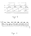
- the measured BEMF voltage signal of a winding 4a-c before completion of the correction process still an approximate rectangular pulse shape, as shown in the first periods of waveform a of Figure 5 for a motor phase is exemplified.
- Curve form b shows the energized and de-energized state of a winding 4a-c; when the respective winding 4a-c is de-energized, the voltage fluctuates greatly back and forth (gray area), while it is at a fixed positive or negative value in the energized state.
- the no-current time interval should coincide with the falling and rising edges of a characteristic trapezoidal BEMF voltage signal.
- looking at waveform b it can be seen that the falling and rising edges are initially jumps at the beginning of the de-energized phase.
- the processor 2 determines from the sensed BEMF voltage signal in successive de-energized states of a winding 4a-c, whether the two consecutive rising and falling edges of the BEMF voltage signal each have the same slope of opposite sign. In addition, it determines the sum of successively measured BEMF voltage values per state from consecutively no-current states. Due to the symmetry of the characteristic trapezoidal BEMF voltage signal, both the edge slopes within one state and the sum values of successive no-current states should match.
- FIG. 6 shows the effects of this measure: the value of the angle pointer increases by the correction value KW.
- the correction already causes the fourth commutation step, since it has been shifted forward in time, while the third commutation step has been shortened. Accordingly, the commutation times are made to a different rotor position, which should ensure better efficiency.
- the magnitude and sign of the correction value may be selected depending on the degree of agreement, e.g., the magnitude of the correction value may be linearly dependent on the deviation of the slope amounts and / or the sum values and its sign on the sign of the difference of the slope amounts and / or the sum values.
- the sum of the correction values determined in all steps represents the angular offset between the absolute rotor position and the relative sensor signal.
- the last value corrected in the rotor position determination phase to a synchronization point and then stored corresponds to the absolute rotor position at the time of a Hall signal.
- the processor can now cause the excitation of the motor at the right time during the operating phase.
- the commutation times were already optimally shifted during the rotor position determination phase;
- the processor knowing the angular offset or the absolute rotor position, ensures that the angle counter at each synchronization point corresponds to the last stored value representing the absolute rotor position.
- FIG. 7 shows in curve a a curve of the angle counter corrected only for the synchronization point S, while in curve b the angle counter is corrected in the sum with the same correction value but distributed over a plurality of points in time and the motor operation is thus optimized for concentricity.
- the concentricity optimization thus distributes the shortening or extension of the angle counter caused by the correction value of one synchronization point to the other on all Kommutéessintervalle.
- the processor increases the angle counter depending on the commutation at several times, not just at a time.
- a detection of the induced voltage is no longer necessary after the determination of the absolute position.
- any commutation mode can be applied, without having to take into account the energization of the individual windings (for example, a sinusoidal commutation can take place).
- the rotor position determination phase can be repeated at any time, even during operation of the engine. For this purpose, only switching over to a suitable type of commutation, such as block commutation, is required.
- the above explanations are to be understood as exemplary.
- the induced voltage can be detected and evaluated in another way in order to determine the angular offset or the absolute rotor position.
- Another software implementation can be used.
- the invention combines for the purpose of an unobtrusive derivation of the optimal excitation timing two rotor position determination method such that they complement each other while avoiding typical procedural disadvantages.
- the invention saves the protective enclosure that protects the sensor from corrosive fumes, moisture or other external influences, cable entry from the engine compartment to the electronics compartment, and mounting and aligning the sensor inside the engine.
- the sensor according to the invention since the sensor according to the invention only has to provide relative information available, for example, when measuring with Hall sensors one to two Hall sensors can be saved.
- the rotor position does not need to be exclusively induced by measuring the induced Voltage can be determined, but is the choice of Kommut istsart outside the rotor position determination phase absolutely free.
- a magnetic cap with one to two Hall sensors, a circuit for detecting the induced voltage and possibly an extension of the motor shaft.
- all these components are relatively inexpensive to implement, since, for example, the Hall sensors and the circuit for detecting the induced voltage in the same operation as the other components can be mounted on the board / boards.
- the magnetic cap can be designed as an injection molded part and equipped with small magnets.
- the extension of the motor shaft is usually unproblematic. Overall, this results in a significant effort and thus cost savings.
- the motor speed increases, it may become necessary to further shorten the detection of the BEMF voltage signal during the non-energized states of a winding, since the non-energized winding requires a certain time for demagnetization.
- the phase current of the immediately preceding energized state continues to flow in the same direction, but drops to zero.
- the BEMF voltage can not be detected because the potential of the de-energized state via the inverse diodes is at the positive or negative DC link potential.
- the duration of demagnetization depends proportionally on the rotational speed and can be considered by the processor 2 accordingly.
- the inverter 1 can be operated as a 2-quadrant controller (which advantageously has low switching losses), in which one of the two associated switches 10a-f is permanently switched on, while the other is continuously switched in accordance with the pulse-width-modulated signal specified by the processor 2 is switched on and off.
- the current only increases within the winding 4a-c when both switches are turned on, while otherwise it is free-running (during the pulse break of the pulse width modulated control signal) via the associated inverse diode 11a-f and the switched-in switch 10a-f and depending on the winding resistance and the characteristics of this switch 10a-f drops.
- the inverter 1 can also be operated as a 4-quadrant controller, in which both a winding 4a-c associated switches are switched simultaneously. This operating mode can advantageously be used for rapid changes of direction and / or for active braking of a load.
- a 12-step block commutation with a more even torque generation and concomitant lower noise may be applied, in which an intermediate step is inserted between each step of the 6-step block commutation in which all three phases be energized. While the BEMF voltage signal can not be detected during these intermediate steps, it is sufficient to detect it during the remaining six steps, each time with one no-current winding, to determine the absolute rotor position.
- the electric motor can be designed as an external rotor motor with a bell-shaped rotor.
- the bell-shaped rotor forms the motor housing together with a stator plate in this type of motor.
- the stator attached to the stator plate.
- the stator plate has a centrally recessed socket for mounting the motor shaft.
- the electric motor can be of any kind.
- the electric motor or external rotor motor serves, for example, as a drive for a fan, in which case, in the case of the external rotor motor, connecting stubs for fastening fan blades can be provided directly on the rotor.
Landscapes
- Engineering & Computer Science (AREA)
- Power Engineering (AREA)
- Control Of Motors That Do Not Use Commutators (AREA)
Priority Applications (2)
| Application Number | Priority Date | Filing Date | Title |
|---|---|---|---|
| EP05027095A EP1796258B1 (fr) | 2005-12-12 | 2005-12-12 | Moteur électrique et procédé de son excitation |
| DE502005005763T DE502005005763D1 (de) | 2005-12-12 | 2005-12-12 | Elektromotor und Verfahren zum Anregen eines solchen |
Applications Claiming Priority (1)
| Application Number | Priority Date | Filing Date | Title |
|---|---|---|---|
| EP05027095A EP1796258B1 (fr) | 2005-12-12 | 2005-12-12 | Moteur électrique et procédé de son excitation |
Publications (2)
| Publication Number | Publication Date |
|---|---|
| EP1796258A1 true EP1796258A1 (fr) | 2007-06-13 |
| EP1796258B1 EP1796258B1 (fr) | 2008-10-22 |
Family
ID=37076364
Family Applications (1)
| Application Number | Title | Priority Date | Filing Date |
|---|---|---|---|
| EP05027095A Ceased EP1796258B1 (fr) | 2005-12-12 | 2005-12-12 | Moteur électrique et procédé de son excitation |
Country Status (2)
| Country | Link |
|---|---|
| EP (1) | EP1796258B1 (fr) |
| DE (1) | DE502005005763D1 (fr) |
Cited By (2)
| Publication number | Priority date | Publication date | Assignee | Title |
|---|---|---|---|---|
| EP2645550A1 (fr) * | 2012-03-26 | 2013-10-02 | C. & E. Fein GmbH | Procédé et dispositif destinés à la commande d'une machine électrique |
| EP2536021A3 (fr) * | 2011-06-16 | 2017-05-03 | Andreas Stihl AG & Co. KG | Moteur électrique fonctionnant sur batterie dans un appareil de travail |
Citations (3)
| Publication number | Priority date | Publication date | Assignee | Title |
|---|---|---|---|---|
| WO2001037420A1 (fr) * | 1999-11-17 | 2001-05-25 | Robert Bosch Gmbh | Procede de demarrage d'un moteur a courant continu sans detecteur ni balai |
| JP2004312834A (ja) * | 2003-04-04 | 2004-11-04 | Nsk Ltd | モータ駆動制御装置および電動パワーステアリング装置 |
| US20050218848A1 (en) * | 2004-03-30 | 2005-10-06 | Genfu Zhou | [startup procedure for sensorless brushless dc motor] |
-
2005
- 2005-12-12 EP EP05027095A patent/EP1796258B1/fr not_active Ceased
- 2005-12-12 DE DE502005005763T patent/DE502005005763D1/de not_active Expired - Lifetime
Patent Citations (4)
| Publication number | Priority date | Publication date | Assignee | Title |
|---|---|---|---|---|
| WO2001037420A1 (fr) * | 1999-11-17 | 2001-05-25 | Robert Bosch Gmbh | Procede de demarrage d'un moteur a courant continu sans detecteur ni balai |
| JP2004312834A (ja) * | 2003-04-04 | 2004-11-04 | Nsk Ltd | モータ駆動制御装置および電動パワーステアリング装置 |
| EP1612927A1 (fr) * | 2003-04-04 | 2006-01-04 | NSK Ltd. | Dispositif de commande de l'entrainement d'un moteur et dispositif de guidage a puissance electrique utilisant ledit dispositif |
| US20050218848A1 (en) * | 2004-03-30 | 2005-10-06 | Genfu Zhou | [startup procedure for sensorless brushless dc motor] |
Cited By (2)
| Publication number | Priority date | Publication date | Assignee | Title |
|---|---|---|---|---|
| EP2536021A3 (fr) * | 2011-06-16 | 2017-05-03 | Andreas Stihl AG & Co. KG | Moteur électrique fonctionnant sur batterie dans un appareil de travail |
| EP2645550A1 (fr) * | 2012-03-26 | 2013-10-02 | C. & E. Fein GmbH | Procédé et dispositif destinés à la commande d'une machine électrique |
Also Published As
| Publication number | Publication date |
|---|---|
| EP1796258B1 (fr) | 2008-10-22 |
| DE502005005763D1 (de) | 2008-12-04 |
Similar Documents
| Publication | Publication Date | Title |
|---|---|---|
| EP1154555B1 (fr) | Système de commutation électronique pour un moteur à courant continu sans balai | |
| DE10054594B4 (de) | Vorrichtung zum Erfassen der Rotorposition in einem bürstenlosen Gleichstrommotor | |
| EP3262748B1 (fr) | Disposition des circuits et procédé de commutation sans capteur | |
| EP1579564A2 (fr) | Ensemble de detection de la position d'un rotor et procede de detection de la position d'un rotor | |
| EP1727268A2 (fr) | Procédé pour faire fonctionner un moteur à commutation électronique et moteur pour la mise en oeuvre dudit procédé | |
| DE102015120845B4 (de) | Verfahren zum Ansteuern von bürstenlosen Motoren, entsprechende Vorrichtung, Motor und Computerprogrammprodukt | |
| EP1611670B1 (fr) | Ensemble circuit et procede d'excitation d'un moteur a courant continu a aimants permanents sans balais | |
| EP2550507B1 (fr) | Procédé et dispositif de détermination de la position angulaire actuelle d'un élément magnétique rotatif dans un moteur électrique | |
| DE102017117109A1 (de) | Ansteuerung eines bürstenlosen Gleichstrommotors | |
| WO2005060085A1 (fr) | Commande d'un moteur a courant continu sans balais | |
| EP2645550B1 (fr) | Procédé et dispositif destinés à la commande d'une machine électrique | |
| EP3318764B1 (fr) | Pompe à vide avec protection contre un excès de vitesse | |
| EP1796258B1 (fr) | Moteur électrique et procédé de son excitation | |
| DE60302755T2 (de) | Verfahren und System zur Bestimmung für die elektronische Kommutierung in bürstenloser Gleichstrommaschine unabhängig von der Postionierung des Rotorlagesensors | |
| DE102012012762B4 (de) | Einrichtung zur Bestimmung von Positionen eines Rotors in elektrischen Maschinen | |
| WO2021074094A1 (fr) | Procédé de fonctionnement d'un moteur électrique polyphasé sans balai et sans capteur | |
| BE1029061B1 (de) | Verfahren zum Ansteuern eines mindestens zweiphasigen bürstenlosen Motors | |
| EP4037178B1 (fr) | Procédé de commande d'un moteur sans balai au moins biphasé | |
| DE112011101703B4 (de) | Verfahren zur Regelung der Rotorlage eines elektrisch kommutierten Motors | |
| DE102019215854A1 (de) | Verfahren zum Betreiben eines bürstenlosen und sensorlosen mehrphasigen Elektromotors | |
| DE102013201241A1 (de) | Verfahren und Einrichtung zur Bestimmung der Position des Rotors bei einem bürstenlosen Gleichstrommotor | |
| EP4037183B1 (fr) | Surveillance thermique de deux moteurs | |
| BE1029062B1 (de) | Verfahren zum Ansteuern eines mindestens zweiphasigen bürstenlosen Motors | |
| DE102018119729A1 (de) | Verfahren zum Ansteuern eines Elektromotors und Elektromotor | |
| DE102018119723A1 (de) | Verfahren zum Ansteuern eines Elektromotors und Elektromotor |
Legal Events
| Date | Code | Title | Description |
|---|---|---|---|
| PUAI | Public reference made under article 153(3) epc to a published international application that has entered the european phase |
Free format text: ORIGINAL CODE: 0009012 |
|
| AK | Designated contracting states |
Kind code of ref document: A1 Designated state(s): AT BE BG CH CY CZ DE DK EE ES FI FR GB GR HU IE IS IT LI LT LU LV MC NL PL PT RO SE SI SK TR |
|
| AX | Request for extension of the european patent |
Extension state: AL BA HR MK YU |
|
| 17P | Request for examination filed |
Effective date: 20070622 |
|
| 17Q | First examination report despatched |
Effective date: 20070726 |
|
| AKX | Designation fees paid |
Designated state(s): DE |
|
| GRAP | Despatch of communication of intention to grant a patent |
Free format text: ORIGINAL CODE: EPIDOSNIGR1 |
|
| RTI1 | Title (correction) |
Free format text: ELECTRICAL MOTOR AND METHOD FOR IT'S EXCITATION |
|
| RTI1 | Title (correction) |
Free format text: ELECTRICAL MOTOR AND METHOD FOR ITS EXCITATION |
|
| GRAS | Grant fee paid |
Free format text: ORIGINAL CODE: EPIDOSNIGR3 |
|
| GRAA | (expected) grant |
Free format text: ORIGINAL CODE: 0009210 |
|
| AK | Designated contracting states |
Kind code of ref document: B1 Designated state(s): DE |
|
| REF | Corresponds to: |
Ref document number: 502005005763 Country of ref document: DE Date of ref document: 20081204 Kind code of ref document: P |
|
| PLBE | No opposition filed within time limit |
Free format text: ORIGINAL CODE: 0009261 |
|
| STAA | Information on the status of an ep patent application or granted ep patent |
Free format text: STATUS: NO OPPOSITION FILED WITHIN TIME LIMIT |
|
| 26N | No opposition filed |
Effective date: 20090723 |
|
| PGFP | Annual fee paid to national office [announced via postgrant information from national office to epo] |
Ref country code: DE Payment date: 20201216 Year of fee payment: 16 |
|
| REG | Reference to a national code |
Ref country code: DE Ref legal event code: R119 Ref document number: 502005005763 Country of ref document: DE |
|
| PG25 | Lapsed in a contracting state [announced via postgrant information from national office to epo] |
Ref country code: DE Free format text: LAPSE BECAUSE OF NON-PAYMENT OF DUE FEES Effective date: 20220701 |