EP4037183B1 - Surveillance thermique de deux moteurs - Google Patents
Surveillance thermique de deux moteurs Download PDFInfo
- Publication number
- EP4037183B1 EP4037183B1 EP22151946.5A EP22151946A EP4037183B1 EP 4037183 B1 EP4037183 B1 EP 4037183B1 EP 22151946 A EP22151946 A EP 22151946A EP 4037183 B1 EP4037183 B1 EP 4037183B1
- Authority
- EP
- European Patent Office
- Prior art keywords
- motor
- phase
- designed
- brushless motor
- computer
- Prior art date
- Legal status (The legal status is an assumption and is not a legal conclusion. Google has not performed a legal analysis and makes no representation as to the accuracy of the status listed.)
- Active
Links
Images


Classifications
-
- H—ELECTRICITY
- H02—GENERATION; CONVERSION OR DISTRIBUTION OF ELECTRIC POWER
- H02P—CONTROL OR REGULATION OF ELECTRIC MOTORS, ELECTRIC GENERATORS OR DYNAMO-ELECTRIC CONVERTERS; CONTROLLING TRANSFORMERS, REACTORS OR CHOKE COILS
- H02P29/00—Arrangements for regulating or controlling electric motors, appropriate for both AC and DC motors
- H02P29/60—Controlling or determining the temperature of the motor or of the drive
- H02P29/64—Controlling or determining the temperature of the winding
-
- H—ELECTRICITY
- H02—GENERATION; CONVERSION OR DISTRIBUTION OF ELECTRIC POWER
- H02P—CONTROL OR REGULATION OF ELECTRIC MOTORS, ELECTRIC GENERATORS OR DYNAMO-ELECTRIC CONVERTERS; CONTROLLING TRANSFORMERS, REACTORS OR CHOKE COILS
- H02P29/00—Arrangements for regulating or controlling electric motors, appropriate for both AC and DC motors
- H02P29/02—Providing protection against overload without automatic interruption of supply
- H02P29/032—Preventing damage to the motor, e.g. setting individual current limits for different drive conditions
-
- H—ELECTRICITY
- H02—GENERATION; CONVERSION OR DISTRIBUTION OF ELECTRIC POWER
- H02P—CONTROL OR REGULATION OF ELECTRIC MOTORS, ELECTRIC GENERATORS OR DYNAMO-ELECTRIC CONVERTERS; CONTROLLING TRANSFORMERS, REACTORS OR CHOKE COILS
- H02P5/00—Arrangements specially adapted for regulating or controlling the speed or torque of two or more electric motors
-
- H—ELECTRICITY
- H02—GENERATION; CONVERSION OR DISTRIBUTION OF ELECTRIC POWER
- H02P—CONTROL OR REGULATION OF ELECTRIC MOTORS, ELECTRIC GENERATORS OR DYNAMO-ELECTRIC CONVERTERS; CONTROLLING TRANSFORMERS, REACTORS OR CHOKE COILS
- H02P6/00—Arrangements for controlling synchronous motors or other dynamo-electric motors using electronic commutation dependent on the rotor position; Electronic commutators therefor
- H02P6/04—Arrangements for controlling or regulating the speed or torque of more than one motor
Definitions
- the invention relates to a control device for thermal monitoring of at least two at least two-phase motors according to patent claim 1 and a household appliance with such a control device according to patent claim 8.
- Electric drives include synchronous motors as single-phase or three-phase synchronous machines in motor operation.
- the rotor or runner has a constant magnetization, which is synchronously driven by a moving magnetic rotating field in the stator during operation, resulting in the rotary or rotational movement of the rotor within the stator or stator.
- the three-phase winding of the stator usually with three strands, is controlled by a suitable circuit in such a way that a moving magnetic field is generated by the stator coils, which pulls the rotor along and thereby sets it in rotation.
- the rotary or rotational movement of the rotor of the running synchronous motor is synchronous with the alternating voltage of the stator windings.
- the speed of the rotary movement of the rotor is linked to the frequency of the alternating voltage via the number of pole pairs of the stator windings.
- the magnetic field of the rotor can be generated by permanent magnets, which is known as self-excitation.
- the electrical contact between the stator and rotor can be dispensed with.
- Such permanent-magnet synchronous motors with switching electronics are therefore usually also referred to as brushless motors (brushless direct current motors - BLDC motors for short).
- the coil strands of the stator can be controlled via a four-quadrant controller.
- the electronics for controlling the bridge are a regulated frequency converter.
- Brushless motors are usually designed as three-phase motors, as they then have the advantage of a defined rotor position with high dynamics, high torque and high efficiency.
- a characteristic feature of brushless motors is their commutation, which, for example, in a three-phase stator consists of six blocks or sectors per rotating field cycle, ie per motor revolution, each of which differs from the switching state of the bridge circuit. Only two push-pull stages of the bridge are active at any one time and the third push-pull stage is in the "floating" state.
- the voltage at this bridge point is defined by the circuit network according to the star equivalent circuit diagram.
- the bridge control ensures that the motor phase is always "floating" and - with trapezoidal counter voltage - is just changing polarity.
- the stator field is always in the block with the optimal magnetic flux change, i.e. with the maximum generator voltage.
- the brushless motor thus revs up until its generator voltage corresponds to the supply voltage.
- the maximum speed or operating speed is then reached and is kept constant.
- the speed of the rotor can therefore be controlled or changed by changing the supply voltage.
- the commutation is controlled depending on the current rotor position, which can be detected by at least one position sensor, for example a Hall sensor, which, however, leads to a corresponding additional effort or costs and requires installation space.
- at least one position sensor for example a Hall sensor
- sensorless commutation can be implemented and position sensors can be dispensed with by determining the current rotor position indirectly by measuring electrical parameters on the coils. For example, the EMF (electromotive force) triggered in the stator coils can be recorded and evaluated by the electronic control circuit, although this can only be done from a certain minimum speed.
- EMF electrotive force
- a brushless motor is, from a structural point of view, a rotating field machine that does not require a mechanical commutator.
- the rotor contains one or more permanent magnets. The interaction between the stator field and the rotor field creates an electrical moment that can lead to rotation.
- a motor inverter is usually required to operate a brushless motor.
- the motor inverter usually contains a controller and power semiconductors to control the motor phases. There is also usually an intermediate circuit from which the brushless motor is fed.
- a brushless motor for example, only two of three phases are energized at the same time and the third phase is de-energized.
- the selection of the phases to be energized depends on the rotor position.
- the transition from one sector or block to the next is also called “electronic commutation”; hence the term “brushless” or “electronically commutated”.
- the information about the rotor position required for the commutation of a brushless motor is usually transmitted via a Position sensors such as Hall sensors, resolvers or incremental encoders are used.
- a star point can be artificially simulated using three resistors connected in star.
- the voltage potential of the artificial star point is then compared with the voltage potential of the inactive phase, for example via a comparator. The zero crossing of this difference is used as the reference time for commutation.
- Such brushless motors can overheat if the phases are energized by the controlled frequency converter as described above, but the resulting rotary motion of the rotor is completely blocked or at least impeded mechanically. The latter can also be due to the rotor or the mechanical element being driven being stiff. Incorrect or faulty control of the controlled frequency converter or the control hardware can also lead to the desired rotary motion of the rotor not being able to be generated at all or only to an insufficient extent.
- the energization of the phases can lead to heating of the stator coils, which can exceed the permissible temperature and thus overheat the brushless motor. This can lead to damage to the coils, the controlled frequency converter and other electronic elements and possibly to a failure of the brushless motor.
- Such thermal monitoring is usually implemented indirectly by not measuring the temperature of the brushless motor itself, but by providing a temperature sensor near the brushless motor or its stator coils, which can measure the ambient air temperature. The temperature of the air in the vicinity of the coils of the stator of the brushless motor is thus measured by sensors and reacted to as described above.
- Such indirect temperature monitoring can usually provide sufficient protection against overheating or overheating in such brushless motors if the aim is to react to a slow heating of the brushless motor, which has sufficient time to warm up the ambient temperature and thus be detected by the temperature sensor. This can be the case with a reduced speed of the rotor of the brushless motor.
- stator coils of the brushless motor heat up very quickly, for example because the rotor of the brushless motor has stopped, this cannot usually be detected quickly enough using the indirect thermal monitoring described above to be able to react to it and prevent damage to the brushless motor.
- the thermal coupling between the stator coils of the brushless motor and the temperature sensor which usually takes place over several centimeters of ambient air, is so poor or occurs so slowly that the time delay caused by this is too long to be able to detect the overheating or overheating of the coils of the brushless motor quickly enough to be able to react effectively by switching off the brushless motor.
- thermal monitoring is usually provided redundantly, ie the same thermal monitoring is provided at least twice and operates in parallel and independently of each other in order to be able to continue to provide the previously described thermal monitoring as a safety function even if one of the two thermal monitoring is faulty or has failed. This does lead to a corresponding increase in costs and installation space as well as an additional need for electrical energy.
- thermal monitoring of brushless motors is a safety-critical factor, this effort can be justified. This can even lead to three thermal monitoring systems being provided in parallel in order to be able to reliably detect or prevent overheating of the brushless motor.
- the DE 102014008642 A1 refers to a temperature estimation device that estimates a temperature of a power semiconductor chip selected for temperature estimation, which is one or more of power semiconductor chips included in a power semiconductor module, the number of which is equal to or greater than the number of motors, and which are arranged in the same heat sink for driving a plurality of motors.
- the KR 20200084835 A relates to a vacuum cleaner having a drum with a brush installed therein, a first motor for rotating the drum, a sensor for detecting a load applied to the first motor, a second motor for generating a suction pressure, and a processor for controlling the first motor or the second motor based on the load.
- the EP2731218A1 relates to a frequency converter for operating an electric motor, comprising a rectifier, an inverter with controlled half-bridges for switching the power supply for at least one winding of a single-phase or multi-phase electric motor on and off, a control device for controlling the half-bridges, and also a device for determining the current in at least one supply line to the frequency converter.
- the device is designed to determine a total current based on individually detected phase currents by means of the control device.
- the invention addresses the problem of providing a control device for thermal monitoring of at least two at least two-phase motors, of which at least one is a brushless motor, so that their redundant thermal monitoring can be carried out with reduced effort.
- this should be able to be implemented as simply, inexpensively and/or flexibly as possible.
- At least an alternative to known control devices of this type should be created.
- the invention relates to a control device for thermally monitoring at least two at least two-phase motors, preferably without a rotor position sensor, with a first computer which is designed to thermally monitor both the first brushless motor and the second motor, and with a second computer which is designed to thermally monitor both the first brushless motor and the second motor.
- two computers of the control device which are preferably already present, are used not only to operate and thermally monitor their "own” motor, but also to thermally monitor the "foreign” motor of the other computer.
- each computer can monitor its own motor and, if a thermal overload is detected, adjust or stop its operation accordingly. If a computer detects a thermal overload in the "foreign” motor, this computer can inform the other computer of the "foreign” motor and thus cause the operation of the "foreign” motor to be adjusted or stopped accordingly.
- both computers are designed to reduce the power of both the first brushless motor and the second motor or to stop them if a thermal overload is detected by at least one of the two computers. This can increase safety because the detection of a thermal overload of a motor by just one of the two computers is sufficient to trigger a reaction. This can ensure the implementation of the thermal monitoring if this function does not work on the other of the two computers.
- both computers are designed to reduce the power of both the first brushless motor and the second, preferably also brushless, motor or to stop them if a thermal overload is detected by both computers. This can prevent the thermal monitoring function from leading to the detection of a supposed thermal monitoring in only one of the two computers, as this is only detected by the second computer. must be confirmed in order to actually trigger a reaction. This can avoid an unnecessary or unjustified reaction to an incorrectly assessed condition of the corresponding engine.
- the control device has a first current meter of the first brushless motor, which is designed to detect a phase current of the first brushless motor and to make it available to the first computer, and a second current meter of the first brushless motor, which is designed to detect the phase current of the first brushless motor and to make it available to the second computer, wherein the two computers are designed to compare the two detected phase currents of the first brushless motor with each other and, in the event of a predetermined deviation, to reduce the power of the first brushless motor or to stop it.
- one of the two phase current measurements may be considered faulty.
- the reliability of the thermal monitoring which is based on the two recorded phase currents, may no longer be guaranteed. Accordingly, the operation of the corresponding motor may be reduced or stopped because its thermal monitoring can no longer be carried out reliably.
- the control device has a first current meter of the second motor, which is designed to detect a phase current of the second motor and to make it available to the second computer, and a second current meter of the second motor, which is designed to detect the phase current of the second motor and to make it available to the first computer, wherein the two computers are designed to compare the two detected phase currents of the second motor with one another and, in the event of a predetermined deviation, to reduce the power of the second motor or to stop it.
- the control device has a first voltmeter of the first brushless motor, which is designed to detect a phase voltage of the first brushless motor and to make it available to the first computer, and a second voltmeter of the first brushless motor, which is designed to detect the phase voltage of the first brushless motor and to make it available to the second computer, wherein the two computers are designed to compare the two detected phase voltages of the first brushless motor with one another and, in the event of a predetermined deviation, to reduce the power of the first brushless motor or to stop it.
- the control device has a first voltmeter of the second motor, which is designed to detect a phase voltage of the second motor and to make it available to the second computer, and a second voltmeter of the second motor, which is designed to detect the phase voltage of the second motor and to make it available to the first computer, wherein the two computers are designed to compare the two detected phase voltages of the second motor with each other and, in the event of a predetermined deviation, to reduce the power of the second motor or to stop it.
- the invention also relates to a household appliance with at least two at least two-phase motors, preferably without a rotor position sensor, and with a control device as described above.
- a control device as described above.
- the household appliance is a vacuum cleaner, wherein the first brushless motor is designed to drive a fan, and wherein the second, preferably also brushless, motor is designed to drive a floor brush. Since such a vacuum cleaner usually has two motors anyway, the implementation of a control device according to the invention can be particularly simple and effective, particularly in such a household appliance. In particular, implementation of a redundant thermal monitoring according to the invention in a vacuum cleaner can reduce or keep its weight and/or size low, which can be viewed as advantageous by the user.
- the household appliance has a preferably rechargeable electrical energy storage device and is designed to be operated using the electrical energy stored in the electrical energy storage device. Since the redundant thermal monitoring according to the invention also allows the electrical energy required for this to be kept low, its implementation in a household appliance with an electrical energy storage device can keep its energy requirements low and thus increase the service life of the household appliance.
- Figure 1 shows a circuit of a known brushless motor M.
- the brushless motor M or BLDC motor M for short, is controlled or operated via a control unit S in the form of a regulated frequency converter S.
- a three-phase rotating field is applied to the BLDC motor M from a direct voltage V DC as intermediate circuit voltage V DC via a B6 bridge with six switching elements (MOSFETs or transistors) T1-T6 and six diodes D1-D6. This causes a rotation of a rotor (not shown) of the BLDC motor M during operation.
- MOSFETs or transistors six switching elements
- the rotor position In order for the rotating field applied to the stator (not shown) of the BLDC motor M to match the rotor position, the rotor position must be determined. In the past, this was done using a sensor on the BLDC motor M. With the advent of sensorless control, the sensor was replaced by the measurement of electrical quantities in combination with a software motor model by the control unit S. For this purpose, the phase voltages U Phase of the three phases U, V, W and also the star point voltage were measured. The star point voltage can either be measured at the star point of the BLDC motor M or simulated and measured using an "artificial star point".
- the circuit of the ohmic resistors R8-R10 and the capacitor C5 represents the artificial star point. In a BLDC motor M with a delta connection, only the artificial star point is usually used.
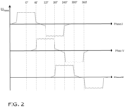
- FIG 2 shows the waveforms of the phase voltages U Phase of the three phases U, V, W of the brushless motor M of the Figure 1 .
- the phase U is actively subjected to a positive voltage for 120° (two sectors).
- the phase U is de-energized for one sector.
- the induced voltage EMF of the phase U can be measured, which is also referred to as the electromotive force (EMF).
- EMF electromotive force
- the zero line for the phase voltage U phase is the star point voltage. Where the phase voltage U phase crosses the star point voltage, there is a so-called zero crossing of the respective phase voltage U phase . This point in time of the zero crossing of the phase voltage U phase is the moment when the stator and the rotor are aligned with each other. Measurements are made at these zero crossings. This means that in phase U of a single-pole BLDC motor M, a zero crossing can be measured twice during one mechanical revolution (0° to 360°). If you measure the current in all three phases U, V, W, the rotor position can be determined six times during one mechanical revolution. All control units S of conventional BLDC motors M are based on this principle.
- Such BLDC motors M can be used, for example, in battery-operated handheld vacuum cleaners, or battery-operated vacuum cleaners for short, which typically have two such drives.
- a first BLDC motor M1 is used as a blower motor and on the other hand, a second BLDC motor M2 is used to drive the floor brush (the second motor does not necessarily have to be brushless, but can alternatively be brushed).
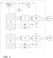
- Both BLDC motors M1, M2 are controlled by an electronic control device, see Figure 3 .
- Each of the two BLDC motors M1, M2 has thermal monitoring, which is implemented by the control device.
- Thermal monitoring is necessary because incorrect control of the BLDC motors M1, M2 or a blocked rotor of one of the BLDC motors M1, M2 can lead to a high current in the coils of the corresponding BLDC motor M1, M2 and thus to overheating or overheating of the BLDC motor M1, M2.
- the first BLDC motor M1 is shown as a three-phase fan motor M1 which is controlled by a classic three-phase inverter WR via a first driver T1.
- the second BLDC motor M2 is a two-phase floor brush motor M2 which is controlled by an H-bridge HB via a second driver T2.
- the temperature of the first BLDC motor M1 can be monitored by a first computer R1 by measuring electrical variables such as the intermediate circuit voltage V DC using a voltmeter Spzs, the motor current using a first ammeter St1 and the phase voltage U Phase using a first voltmeter Sp1.
- the first computer R1 can determine how long a certain current has flowed and can protect the first BLDC motor M1 against overheating using a thermal motor model.
- the first computer R1 can detect when the first BLDC motor M1 is getting too hot, i.e. when a temperature limit is reached or exceeded. If overtemperature is detected, the first BLDC motor M1 is switched off using the inrush current limit Est.
- the control device has a first current meter St1 and a first voltage meter Sp1 for the second BLDC motor M2 as well as a second computer R2.
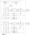
- thermal monitoring is provided in duplicate by redundantly measuring the electrical quantities described above as well as evaluating them, as described in the Figure 4 No two additional computers are used for this, because this would be too complex and expensive to carry out only the reduced range of functions of thermal monitoring.
- two analog circuits A1a, A2a are used, each of which is fed the separately recorded motor current and the separately recorded phase voltage U Phase independently of the respective computer R1, R2.
- the control device has a second current meter St1a and a second voltmeter Sp1a of the first BLDC motor M1, which make their recorded variables available to the first analog circuit A1a.
- control device has a second current meter St2a and a second voltmeter Sp2a of the second BLDC motor M2, which make their recorded variables available to the second analog circuit A2a.
- first BLDC motor M1 and the second BLDC motor M2 can each be redundantly thermally monitored and protected from overheating or overheating.
- the use of the two analog circuits A1a, A2a is usually very complex because the electrical variables have to be combined with each other in a sensible way. Complex means that the two analog circuits A1a, A2a each consist of many individual electronic parts or are implemented using expensive programmable logic. In any case, this also leads to considerable additional costs in order to obtain redundant thermal monitoring for both BLDC motors M1, M2.
- the values recorded by the second ammeter St1a and the second voltmeter Sp1a of the first BLDC motor M1 are fed to the second computer R2, so that thermal monitoring of the first BLDC motor M1 can be carried out independently on both the first computer R1 and the second computer R2, which is based on the same values, but which are recorded twice, independently of each other. If a thermal overload is detected by one of the two computers R1, R2, this can be responded to as described above. This applies accordingly to the second BLDC motor M2. This can be communicated between the two computers R1, R2 in order to implement the corresponding reaction on the affected BLDC motor M1, M2.
- a thermal overload can only be considered as detected if both computers R1, R2 come to this result, since they have the same values of the motor current and the phase voltage U Phase of both the first BLDC motor M1 and the second BLDC motor M2 are received and processed in the same way, so that if the process is carried out correctly, the result of the two computers R1, R2 must also be the same. Otherwise, it can be assumed that one of the two computers R1, R2 incorrectly detects a thermal overload of one of the two BLDC motors M1, M2 and a reaction can be omitted in order not to unjustifiably disrupt the operation of the affected BLDC motor M1, M2.
- the two computers R1, R2 can also compare whether the sizes of the motor current and/or the phase voltage U Phase of the first BLDC motor M1 were correctly recorded by the first ammeter St1 and by the second ammeter St1a as well as by the first voltmeter Sp1 and by the second voltmeter Sp1a by comparing the twice recorded values of these sizes. If the values of these sizes match to a sufficient extent, which can be specified by a predetermined tolerance limit, it can be assumed that these sizes were recorded correctly. Accordingly, operation of the first BLDC motor M1 can continue, provided the thermal monitoring allows this. Otherwise, operation of the first BLDC motor M1 can also be terminated, since its thermal monitoring can no longer be guaranteed in this case, as described above. This also applies to the first BLDC motor M2.
Landscapes
- Engineering & Computer Science (AREA)
- Power Engineering (AREA)
- Control Of Motors That Do Not Use Commutators (AREA)
Claims (9)
- Dispositif de commande pour la surveillance thermique d'au moins deux moteurs (M1, M2) au moins biphasés, de préférence sans capteur de position de rotor,comportant un premier calculateur (R1) qui est configuré pour surveiller thermiquement à la fois le premier moteur (M1) sans balais et le second moteur (M2), de préférence sans balais, etcomportant un second calculateur (R2) qui est configuré pour surveiller thermiquement à la fois le premier moteur (M1) sans balais et le second moteur (M2), caractérisé en ce queles deux calculateurs (R1, R2) sont configurés pour réduire respectivement la puissance à la fois du premier moteur (M1) sans balais et du second moteur (M2) ou pour les arrêter dans le cas où une surcharge thermique est détectée par au moins l'un des deux calculateurs (R1, R2).
- Dispositif de commande selon la revendication 1, caractérisé en ce que les deux calculateurs (R1, R2) sont configurés pour réduire respectivement la puissance à la fois du premier moteur (M1) sans balais et du second moteur (M2) ou pour les arrêter dans le cas où une surcharge thermique est détectée par les deux calculateurs (R1, R2).
- Dispositif de commande selon l'une des revendications précédentes, caractérisé parun premier ampèremètre (St1) du premier moteur (M1) sans balais, lequel premier ampèremètre est configuré pour détecter un courant de phase du premier moteur (M1) sans balais et pour le mettre à la disposition du premier calculateur (R1), et parun second ampèremètre (St1a) du premier moteur (M1) sans balais, lequel second ampèremètre est configuré pour détecter le courant de phase du premier moteur (M1) sans balais et pour le mettre à la disposition du second calculateur (R2),dans lequel les deux calculateurs (R1, R2) sont configurés pour comparer respectivement les deux courants de phase détectés du premier moteur (M1) sans balais entre eux et, en cas d'écart prédéterminé, pour réduire la puissance du premier moteur (M1) sans balais ou pour l'arrêter.
- Dispositif de commande selon l'une des revendications précédentes, caractérisé parun premier ampèremètre (St2) du second moteur (M2), lequel premier ampèremètre est configuré pour détecter un courant de phase du second moteur (M2) et pour le mettre à la disposition du second calculateur (R2), et parun second ampèremètre (St2a) du second moteur (M2), lequel second ampèremètre est configuré pour détecter le courant de phase du second moteur (M2) et pour le mettre à la disposition du premier calculateur (R1),dans lequel les deux calculateurs (R1, R2) sont configurés pour comparer respectivement les deux courants de phase détectés du second moteur (M2) entre eux et, en cas d'écart prédéterminé, pour réduire la puissance du second moteur (M2) ou pour l'arrêter.
- Dispositif de commande selon l'une des revendications précédentes, caractérisé parun premier voltmètre (Sp1) du premier moteur (M1) sans balais, lequel premier voltmètre est configuré pour détecter une tension de phase (UPhase) du premier moteur (M1) sans balais et pour la mettre à la disposition du premier calculateur (R1), et parun second voltmètre (Sp1a) du premier moteur (M1) sans balais, lequel second voltmètre est configuré pour détecter la tension de phase (UPhase) du premier moteur (M1) sans balais et pour la mettre à la disposition du second calculateur (R2),dans lequel les deux calculateurs (R1, R2) sont configurés pour comparer respectivement les deux tensions de phase (UPhase) détectées du premier moteur (M1) sans balais entre elles et, en cas d'écart prédéterminé, pour réduire la puissance du premier moteur (M1) sans balais ou pour l'arrêter.
- Dispositif de commande selon l'une des revendications précédentes, caractérisé parun premier voltmètre (Sp2) du second moteur (M2), lequel premier voltmètre est configuré pour détecter une tension de phase (UPhase) du second moteur (M2) et pour la mettre à la disposition du second calculateur (R2), et parun second voltmètre (Sp2a) du second moteur (M2), lequel second voltmètre est configuré pour détecter la tension de phase (UPhase) du second moteur (M2) et pour la mettre à la disposition du premier calculateur (R1),dans lequel les deux calculateurs (R1, R2) sont configurés pour comparer respectivement les deux tensions de phase (UPhase) détectées du second moteur (M2) entre elles et, en cas d'écart prédéterminé, pour réduire la puissance du second moteur (M2) ou pour l'arrêter.
- Appareil électroménagercomportant au moins deux moteurs (M1, M2) au moins biphasés, dans lequel un premier moteur (M1) est sans balais, de préférence sans capteur de position de rotor, etcomportant un dispositif de commande selon l'une des revendications précédentes.
- Appareil électroménager selon la revendication 7, caractérisé en ce quel'appareil électroménager est un aspirateur,dans lequel le premier moteur (M1) sans balais est conçu pour entraîner une soufflante, etdans lequel le second moteur (M2) est conçu pour entraîner une brosse pour sol.
- Appareil électroménager selon la revendication 7 ou 8,
caractérisé en ce que
l'appareil électroménager présente un accumulateur d'énergie électrique, de préférence rechargeable, et est configuré pour fonctionner au moyen de l'énergie électrique accumulée de l'accumulateur d'énergie électrique.
Applications Claiming Priority (1)
| Application Number | Priority Date | Filing Date | Title |
|---|---|---|---|
| BE20215065A BE1029063B1 (de) | 2021-01-28 | 2021-01-28 | Thermische Überwachung zweier Motoren |
Publications (3)
| Publication Number | Publication Date |
|---|---|
| EP4037183A1 EP4037183A1 (fr) | 2022-08-03 |
| EP4037183B1 true EP4037183B1 (fr) | 2024-09-18 |
| EP4037183C0 EP4037183C0 (fr) | 2024-09-18 |
Family
ID=74504966
Family Applications (1)
| Application Number | Title | Priority Date | Filing Date |
|---|---|---|---|
| EP22151946.5A Active EP4037183B1 (fr) | 2021-01-28 | 2022-01-18 | Surveillance thermique de deux moteurs |
Country Status (2)
| Country | Link |
|---|---|
| EP (1) | EP4037183B1 (fr) |
| BE (1) | BE1029063B1 (fr) |
Family Cites Families (4)
| Publication number | Priority date | Publication date | Assignee | Title |
|---|---|---|---|---|
| EP2731218B1 (fr) * | 2012-11-08 | 2017-03-29 | Miele & Cie. KG | Convertisseur de fréquence pour l'actionnement d'un moteur électrique, système mécatronique et appareil électrique |
| JP5667242B2 (ja) * | 2013-06-10 | 2015-02-12 | ファナック株式会社 | パワー半導体チップの温度を推定する温度推定装置及びそれを備えるモータ制御装置 |
| JP2018186625A (ja) * | 2017-04-25 | 2018-11-22 | ファナック株式会社 | 残留電荷消費制御部を有するモータ駆動装置 |
| KR102436006B1 (ko) * | 2018-05-18 | 2022-08-25 | 삼성전자주식회사 | 진공 청소기 및 진공 청소기의 제어방법 |
-
2021
- 2021-01-28 BE BE20215065A patent/BE1029063B1/de not_active IP Right Cessation
-
2022
- 2022-01-18 EP EP22151946.5A patent/EP4037183B1/fr active Active
Also Published As
| Publication number | Publication date |
|---|---|
| BE1029063A1 (de) | 2022-08-22 |
| EP4037183A1 (fr) | 2022-08-03 |
| BE1029063B1 (de) | 2022-08-29 |
| EP4037183C0 (fr) | 2024-09-18 |
Similar Documents
| Publication | Publication Date | Title |
|---|---|---|
| DE102006008496A1 (de) | Phasenausfallerkennung für eine Drehfeldmaschine | |
| DE102012102868A1 (de) | Verfahren zum Betreiben eines bürstenlosen Elektromotors | |
| WO2013156571A2 (fr) | Commande destinée à un moteur à courant continu sans balai | |
| DE102017102105B4 (de) | INTELLIGENTE ERKENNUNGSEINHEIT (iDU) ZUM ERKENNEN DER POSITION EINES MIT EINER PULSMODULATION GESTEUERTEN ROTORS | |
| EP4372977A1 (fr) | Système d'entraînement | |
| EP4037183B1 (fr) | Surveillance thermique de deux moteurs | |
| US20140125262A1 (en) | Circuit For Monitoring The Operation Of An Electric Motor | |
| EP4030617B1 (fr) | Procédé de surveillance thermique d'un moteur sans balai | |
| EP4033655B1 (fr) | Procédé et dispositif d'entraînement de surveillance thermique d'un moteur sans balai au moins biphasé | |
| DE102012012762B4 (de) | Einrichtung zur Bestimmung von Positionen eines Rotors in elektrischen Maschinen | |
| BE1029061B1 (de) | Verfahren zum Ansteuern eines mindestens zweiphasigen bürstenlosen Motors | |
| EP4358391A1 (fr) | Système d'entraînement | |
| EP4037178B1 (fr) | Procédé de commande d'un moteur sans balai au moins biphasé | |
| EP4187775A1 (fr) | Procédé de commande d'un moteur sans balai au moins biphasé | |
| EP4142146B1 (fr) | Système d'entraînement | |
| BE1029062B1 (de) | Verfahren zum Ansteuern eines mindestens zweiphasigen bürstenlosen Motors | |
| EP1796258B1 (fr) | Moteur électrique et procédé de son excitation | |
| BE1029057B1 (de) | Verfahren zum Ansteuern eines mindestens zweiphasigen bürstenlosen Motors | |
| EP3676951B1 (fr) | Commande d'un moteur de ventilateur pour l'amélioration de la compatibilité électromagnétique | |
| DE102021101628A1 (de) | Verfahren zum Ansteuern eines mindestens zweiphasigen bürstenlosen Motors | |
| EP4593281A1 (fr) | Système d'entraînement | |
| EP4550656A1 (fr) | Procédé de fonctionnement biphasé d'un moteur synchrone triphasé à excitation permanente |
Legal Events
| Date | Code | Title | Description |
|---|---|---|---|
| PUAI | Public reference made under article 153(3) epc to a published international application that has entered the european phase |
Free format text: ORIGINAL CODE: 0009012 |
|
| STAA | Information on the status of an ep patent application or granted ep patent |
Free format text: STATUS: THE APPLICATION HAS BEEN PUBLISHED |
|
| AK | Designated contracting states |
Kind code of ref document: A1 Designated state(s): AL AT BE BG CH CY CZ DE DK EE ES FI FR GB GR HR HU IE IS IT LI LT LU LV MC MK MT NL NO PL PT RO RS SE SI SK SM TR |
|
| STAA | Information on the status of an ep patent application or granted ep patent |
Free format text: STATUS: REQUEST FOR EXAMINATION WAS MADE |
|
| 17P | Request for examination filed |
Effective date: 20230203 |
|
| RBV | Designated contracting states (corrected) |
Designated state(s): AL AT BE BG CH CY CZ DE DK EE ES FI FR GB GR HR HU IE IS IT LI LT LU LV MC MK MT NL NO PL PT RO RS SE SI SK SM TR |
|
| GRAP | Despatch of communication of intention to grant a patent |
Free format text: ORIGINAL CODE: EPIDOSNIGR1 |
|
| STAA | Information on the status of an ep patent application or granted ep patent |
Free format text: STATUS: GRANT OF PATENT IS INTENDED |
|
| INTG | Intention to grant announced |
Effective date: 20240712 |
|
| GRAS | Grant fee paid |
Free format text: ORIGINAL CODE: EPIDOSNIGR3 |
|
| GRAA | (expected) grant |
Free format text: ORIGINAL CODE: 0009210 |
|
| STAA | Information on the status of an ep patent application or granted ep patent |
Free format text: STATUS: THE PATENT HAS BEEN GRANTED |
|
| AK | Designated contracting states |
Kind code of ref document: B1 Designated state(s): AL AT BE BG CH CY CZ DE DK EE ES FI FR GB GR HR HU IE IS IT LI LT LU LV MC MK MT NL NO PL PT RO RS SE SI SK SM TR |
|
| REG | Reference to a national code |
Ref country code: GB Ref legal event code: FG4D Free format text: NOT ENGLISH |
|
| REG | Reference to a national code |
Ref country code: CH Ref legal event code: EP |
|
| REG | Reference to a national code |
Ref country code: DE Ref legal event code: R096 Ref document number: 502022001669 Country of ref document: DE |
|
| REG | Reference to a national code |
Ref country code: IE Ref legal event code: FG4D Free format text: LANGUAGE OF EP DOCUMENT: GERMAN |
|
| U01 | Request for unitary effect filed |
Effective date: 20240918 |
|
| U07 | Unitary effect registered |
Designated state(s): AT BE BG DE DK EE FI FR IT LT LU LV MT NL PT RO SE SI Effective date: 20241007 |
|
| PG25 | Lapsed in a contracting state [announced via postgrant information from national office to epo] |
Ref country code: NO Free format text: LAPSE BECAUSE OF FAILURE TO SUBMIT A TRANSLATION OF THE DESCRIPTION OR TO PAY THE FEE WITHIN THE PRESCRIBED TIME-LIMIT Effective date: 20241218 |
|
| PG25 | Lapsed in a contracting state [announced via postgrant information from national office to epo] |
Ref country code: GR Free format text: LAPSE BECAUSE OF FAILURE TO SUBMIT A TRANSLATION OF THE DESCRIPTION OR TO PAY THE FEE WITHIN THE PRESCRIBED TIME-LIMIT Effective date: 20241219 |
|
| PG25 | Lapsed in a contracting state [announced via postgrant information from national office to epo] |
Ref country code: HR Free format text: LAPSE BECAUSE OF FAILURE TO SUBMIT A TRANSLATION OF THE DESCRIPTION OR TO PAY THE FEE WITHIN THE PRESCRIBED TIME-LIMIT Effective date: 20240918 |
|
| PG25 | Lapsed in a contracting state [announced via postgrant information from national office to epo] |
Ref country code: RS Free format text: LAPSE BECAUSE OF FAILURE TO SUBMIT A TRANSLATION OF THE DESCRIPTION OR TO PAY THE FEE WITHIN THE PRESCRIBED TIME-LIMIT Effective date: 20241218 |
|
| PG25 | Lapsed in a contracting state [announced via postgrant information from national office to epo] |
Ref country code: RS Free format text: LAPSE BECAUSE OF FAILURE TO SUBMIT A TRANSLATION OF THE DESCRIPTION OR TO PAY THE FEE WITHIN THE PRESCRIBED TIME-LIMIT Effective date: 20241218 Ref country code: NO Free format text: LAPSE BECAUSE OF FAILURE TO SUBMIT A TRANSLATION OF THE DESCRIPTION OR TO PAY THE FEE WITHIN THE PRESCRIBED TIME-LIMIT Effective date: 20241218 Ref country code: HR Free format text: LAPSE BECAUSE OF FAILURE TO SUBMIT A TRANSLATION OF THE DESCRIPTION OR TO PAY THE FEE WITHIN THE PRESCRIBED TIME-LIMIT Effective date: 20240918 Ref country code: GR Free format text: LAPSE BECAUSE OF FAILURE TO SUBMIT A TRANSLATION OF THE DESCRIPTION OR TO PAY THE FEE WITHIN THE PRESCRIBED TIME-LIMIT Effective date: 20241219 |
|
| U20 | Renewal fee for the european patent with unitary effect paid |
Year of fee payment: 4 Effective date: 20250131 |
|
| PG25 | Lapsed in a contracting state [announced via postgrant information from national office to epo] |
Ref country code: IS Free format text: LAPSE BECAUSE OF FAILURE TO SUBMIT A TRANSLATION OF THE DESCRIPTION OR TO PAY THE FEE WITHIN THE PRESCRIBED TIME-LIMIT Effective date: 20250118 |
|
| PG25 | Lapsed in a contracting state [announced via postgrant information from national office to epo] |
Ref country code: SM Free format text: LAPSE BECAUSE OF FAILURE TO SUBMIT A TRANSLATION OF THE DESCRIPTION OR TO PAY THE FEE WITHIN THE PRESCRIBED TIME-LIMIT Effective date: 20240918 |
|
| PG25 | Lapsed in a contracting state [announced via postgrant information from national office to epo] |
Ref country code: ES Free format text: LAPSE BECAUSE OF FAILURE TO SUBMIT A TRANSLATION OF THE DESCRIPTION OR TO PAY THE FEE WITHIN THE PRESCRIBED TIME-LIMIT Effective date: 20240918 |
|
| PG25 | Lapsed in a contracting state [announced via postgrant information from national office to epo] |
Ref country code: PL Free format text: LAPSE BECAUSE OF FAILURE TO SUBMIT A TRANSLATION OF THE DESCRIPTION OR TO PAY THE FEE WITHIN THE PRESCRIBED TIME-LIMIT Effective date: 20240918 Ref country code: CZ Free format text: LAPSE BECAUSE OF FAILURE TO SUBMIT A TRANSLATION OF THE DESCRIPTION OR TO PAY THE FEE WITHIN THE PRESCRIBED TIME-LIMIT Effective date: 20240918 |
|
| PG25 | Lapsed in a contracting state [announced via postgrant information from national office to epo] |
Ref country code: SK Free format text: LAPSE BECAUSE OF FAILURE TO SUBMIT A TRANSLATION OF THE DESCRIPTION OR TO PAY THE FEE WITHIN THE PRESCRIBED TIME-LIMIT Effective date: 20240918 |
|
| PLBE | No opposition filed within time limit |
Free format text: ORIGINAL CODE: 0009261 |
|
| STAA | Information on the status of an ep patent application or granted ep patent |
Free format text: STATUS: NO OPPOSITION FILED WITHIN TIME LIMIT |
|
| 26N | No opposition filed |
Effective date: 20250619 |
|
| REG | Reference to a national code |
Ref country code: CH Ref legal event code: PL |
|
| PG25 | Lapsed in a contracting state [announced via postgrant information from national office to epo] |
Ref country code: MC Free format text: LAPSE BECAUSE OF FAILURE TO SUBMIT A TRANSLATION OF THE DESCRIPTION OR TO PAY THE FEE WITHIN THE PRESCRIBED TIME-LIMIT Effective date: 20240918 |
|
| PG25 | Lapsed in a contracting state [announced via postgrant information from national office to epo] |
Ref country code: CH Free format text: LAPSE BECAUSE OF NON-PAYMENT OF DUE FEES Effective date: 20250131 |
|
| PG25 | Lapsed in a contracting state [announced via postgrant information from national office to epo] |
Ref country code: IE Free format text: LAPSE BECAUSE OF NON-PAYMENT OF DUE FEES Effective date: 20250118 |
|
| U20 | Renewal fee for the european patent with unitary effect paid |
Year of fee payment: 5 Effective date: 20260202 |
|
| PGFP | Annual fee paid to national office [announced via postgrant information from national office to epo] |
Ref country code: GB Payment date: 20260126 Year of fee payment: 5 |