EP1799894B1 - Elements de guidage destines a un element de transport a prehenseur d'une machine a filer - Google Patents
Elements de guidage destines a un element de transport a prehenseur d'une machine a filer Download PDFInfo
- Publication number
- EP1799894B1 EP1799894B1 EP05791747.8A EP05791747A EP1799894B1 EP 1799894 B1 EP1799894 B1 EP 1799894B1 EP 05791747 A EP05791747 A EP 05791747A EP 1799894 B1 EP1799894 B1 EP 1799894B1
- Authority
- EP
- European Patent Office
- Prior art keywords
- guide
- gripper
- transport element
- gripper transport
- guides
- Prior art date
- Legal status (The legal status is an assumption and is not a legal conclusion. Google has not performed a legal analysis and makes no representation as to the accuracy of the status listed.)
- Expired - Lifetime
Links
Images
Classifications
-
- D—TEXTILES; PAPER
- D03—WEAVING
- D03D—WOVEN FABRICS; METHODS OF WEAVING; LOOMS
- D03D47/00—Looms in which bulk supply of weft does not pass through shed, e.g. shuttleless looms, gripper shuttle looms, dummy shuttle looms
- D03D47/27—Drive or guide mechanisms for weft inserting
- D03D47/277—Guide mechanisms
-
- D—TEXTILES; PAPER
- D03—WEAVING
- D03D—WOVEN FABRICS; METHODS OF WEAVING; LOOMS
- D03D47/00—Looms in which bulk supply of weft does not pass through shed, e.g. shuttleless looms, gripper shuttle looms, dummy shuttle looms
- D03D47/27—Drive or guide mechanisms for weft inserting
- D03D47/271—Rapiers
- D03D47/272—Rapier bands
Definitions
- the invention relates to a guide element for a gripper transport element of a weaving machine with first guides and with second guides, which together form a positive, one-sided open receptacle for the gripper transport element.
- Gripper transport elements are gripper bars or gripper bands, which are introduced from one side of the loom forth in a shed and thereby introduce a weft.
- the gripper conveyor elements move with the gripper either to the opposite side of the shed or to the middle of the shed, where they meet on a also transported by a gripper conveyor transfer tang, which takes over the registered weft thread and holds or from the middle of the shed to the opposite side transported further.
- the gripper conveyor elements are guided within the shed by means of guide elements. These guide elements are attached to the sley and are moved with the Webladen Gay in a shed and moved back out. They penetrate the lower warp thread of a shed.
- the hook-shaped guide elements which serve to guide a gripper conveyor element designed as a gripper belt have a guide associated with the upper side of the gripper conveyor element and one of the underside of the gripper conveyor element associated guide and a side facing away from the open side guide associated with a side surface of the rapier band is.
- the lower and / or the upper guide engage in a longitudinal groove of the upper side or the lower side of the rapier band, so that the side wall of the longitudinal groove facing the open side of the guide elements is guided on a guide of the guide elements running perpendicular to the upper side and to the lower side.
- This guide and the associated guide surface of the rapier band which is intended to avoid a horizontal deflection of the rapier band in the direction of the open side of the guide elements and thus to the reed, is relatively small. This results in the guide elements and especially but also on the gripper conveyor elements in a relatively short time severe wear.
- the gripper transport element which may also be a flexible rapier band in this case, is guided on the open side of the guide elements by means of two angled portions of the guide elements against dodging in the horizontal direction.
- the top and bottom of the gripper transport element maintain a distance to the opposite regions of the guide elements.
- the gripper transporting member is provided with a passing through the open side of the guide members portion which is guided between the opposite portions of the guide elements in the vertical direction.
- the invention has for its object to provide guide elements of the type mentioned, in which effective guides are increased in the horizontal direction.
- At least one projection protrudes inwardly from the first guides associated with the underside and / or the upper side of the gripper conveying element, which at least one projection complements the second guides with at least one of its side edges.
- the size of the guides effective in the horizontal direction can be increased, so that further surfaces of the gripper transport element can be utilized as guide surfaces. This makes it possible to reduce wear and to improve the guidance of the gripper transport element. It is possible to provide relatively large guides of the guide elements and correspondingly large guide surfaces on the gripper conveyor elements and yet to keep the cross section of the gripper conveyor elements small or to reduce them compared to the previously customary sizes. A reduction in the cross-section of the gripper conveyor elements leads to a reduction in the mass to be moved, which is advantageous for high operating speeds.
- the guides form a substantially C-shaped frame.
- relatively large guides are already possible from the basic structure.
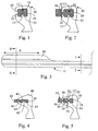
- Guide elements 10 shown which are mounted in a row behind the other on a sley, have a C-shape and are open to a not shown, also attached to the sley reed out. They serve to guide within a shed a gripper transport element 11, which is designed as a gripper bar or gripper belt.
- Fig. 1 and 2 and in 4 to 18 the guide elements are shown in their operating position, ie when they are attached to a sley and the sley is in the position in which a gripper transport element is inserted into a shed and thereby guided by the guide elements.
- the other positions they take when the sash is pivoted are not shown.
- the guide elements each have a guide 12 which is associated with the top of the gripper conveyor element 11, and a guide 13 which is associated with the underside of the gripper conveyor element 11. Between these guides 12 and 13, a guide 14 is provided on the closed side of the guide elements 10, which in the embodiment extends perpendicular to the guides 12, 13 and which is associated with a side surface of the gripper conveyor element 11. On the opposite side of the guide 14, the guides 12 and 13 go over at right angles to extending sections that form guides 15, 16, whose height corresponds to about one third of the guide 14.
- the guides 12, 13, which are associated with the top and the bottom of the gripper conveyor element 11, serve as vertical guides, which prevent a deflection of the gripper conveyor element 11 in the vertical direction.
- the guides 14 on one side and the guides 15, 16 on the other side serve as horizontal guides, which prevent deflection of the gripper conveyor element 11 in the horizontal direction.
- the guides 12, 13, 14, 15 and 16 form a receptacle which secures the gripper transport element in a form-fitting manner against deviations in the horizontal and vertical direction from the movement path and which is open on the side facing a reed, not shown.
- the total height of the guides 15, 16 is in the embodiment by a third smaller than the guide 14. This creates the risk that the gripper conveyor element 11 is exposed to the side of the guides 15, 16 an increased wear.
- the guide 13 is provided with an inwardly projecting projection 17 which engages in a longitudinal groove of the gripper conveyor element 11.
- the projection 17, which in the view Fig. 1 has a preferably rectangular shape, serves with its side edges as a complementary horizontal guide.
- the height of the projection 17 is selected so that the added height of the projection 17 and the guides 15, 16 at least approximately corresponds to the height of the guide 14.
- a gripper transport member 11 will be configured as shown in FIGS. 2 and 3 that is, that it has a widening 18 extending over the entire or a part A of its length, which remains outside of the guide elements 10.
- the sections of the guide elements on the guides 15, 16 opposite outer sides also as a guide, so that the available for the horizontal guide guides are further increased.
- the widening 18 may be a guide member which receives a gripper and is attached to the gripper transport member.
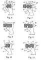
- This in Fig. 4 Guide element 40 shown serves together with a plurality of successively arranged in a row guide elements 40 for guiding a gripper transport element 41, which is designed in particular as a rapier band.
- the gripper transporting member 41 has a substantially flat, rectangular shape so as to be more flexible with respect to a horizontal axis than a vertical axis. Thereby, the gripper transporting member 41 is well suited to be wrapped around a drive wheel rotating back and forth about a horizontal axis.
- the guide element 40 has a guide 42 assigned to the upper side of the gripper transport element 41 and a guide 43 extending parallel thereto and assigned to the underside of the gripper transport element 11.
- the guide element 40 is located on the guide rail 40 a reed, not shown, open side, so that the gripper transport element 41 protrudes slightly out of this page.
- a guide 44 is provided between the guide 42 and the guide 43, which runs perpendicular to the guides 42, 43 and is associated with a side surface of the gripper conveyor element 41.
- two projections 45, 46 inwardly, which have a rectangular shape in the longitudinal direction of the gripper transport element 41 and in two longitudinal grooves engage the gripper transport element 41.
- the two longitudinal grooves and the two projections 45, 46 have the same dimensions in the embodiment and are arranged at the same distance from the longitudinal center plane of the gripper conveyor element 41.
- the height of the two projections, starting from the guide 43, corresponds in the embodiment at least half of the guide 44, so that on the side facing away from the guide 44 due to the added heights of the projections 45 and 46, a guide is present at least approximately Height of the guide 44 corresponds.
- the embodiment of the guide elements 50 according to Fig. 5 corresponds in principle to the structure of the guide elements 40 after Fig. 4 ,
- the underside of the gripper conveyor element 51 is associated with a guide 53, from which two projections 55, 56 protrude inwards.
- protruding from the top of the gripper transport member 51 associated guide 52 projections 57, 58 inwardly, which once again increase the horizontal guides.
- Gripper transport elements in the form of gripper bars or gripper belts are driven by means of drive wheels which are provided with teeth which engage in holes 59 in a row of holes of the gripper bar or gripper belt.
- the gripper conveyor element 51 after Fig. 5 is provided in its longitudinal center with a row of holes holes 59 which extend from the top to the bottom of the Greifeitransportelements 51.
- the projections 55, 56 and 57, 58 are located outside the region of the row of holes, so that the holes 59 can extend over the entire height of the gripper transport element 51, ie are in a region which is not through a longitudinal groove or the like. is weakened.
- the gripper transport element 41 which is provided in the region between the projections 45, 46 intended for longitudinal grooves with the holes of a row of holes.
- the depth of the holes corresponds to the height of the projections 45.
- a projection 61 is provided in the 6 and 7 shown guide elements 10 'differ from the guide elements 10 after Fig. 1 and 2 only in that in addition to the top of the gripper transport member 11 'associated guide 12', a projection 61 is provided.
- the projection 61 is arranged opposite the projection 17. He also has the same size.
- the projections 17 and 61 in the transverse direction are arranged offset.
- the projections 17, 61 also have different dimensions.
- Fig. 8 (Which is essentially the embodiment of Fig. 4 corresponds) is shown, in the guide elements 80, the projections 85 and 86 not - as in the Embodiment after Fig. 4 - Be arranged symmetrically to the central longitudinal axis of the gripper transport member 81 and also do not have the same dimensions in terms of width and depth.
- Fig. 9 shows an embodiment for guide elements 90, wherein from one of the top of a gripper transport member 91 associated guide 92 projects inwardly a projection 96 which is parallel to the located on the closed side of the guide member 90, perpendicular to the guide 92 extending guide 94.
- This projection 96 is offset from a projection 95, which protrudes from the guide 93, which is associated with the underside of the gripper transport element 91, inwardly.
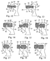
- Fig. 10 shows an embodiment of a guide element 10 ", which is a modification of the guide element 10 after Fig. 1 and 2 is.
- the outer edge of the section with the guide 15 'of the guide element 10 ", which is assigned to this guide surface of the gripper transport element 11" is also aligned obliquely, preferably parallel to the guide 15'.
- the upper edge of the guide element 10 " which is associated with the guide 12 for the top of the gripper transport element 11" also runs slightly obliquely upwards in the direction of the open side.
- the transition between the guide 15 'and the guide 12 associated outer edges is slightly rounded. It forms the highest point of the guide element 10 ".
- the gripper transport element 11 "can accordingly Fig. 1 to 3 be provided with a widening 18 which extends over a part A of its axial length.
- Fig. 11 an embodiment is shown, which is a modification of the embodiment according to Fig. 10 is. How out Fig. 11 As can be seen, the projection 17 'of the guide element 10 "" is somewhat wider.
- the gripper transport element 11 " is shown in the region of its widening 18.
- the guide element 10 "' is extended in the region of its the underside of the gripper transport element 11" associated guide 13 by means of a projection 25 on the between the guides 15', 16 located open side addition.
- the projection 25, which terminates pointedly forms with its top a guide 26 for the underside of the widening 18 and supports the widening 18 against torsional forces.
- the guide element 50 'of Fig. 12 differs from the guide element 50 of the Fig. 5 in that it is provided only with a projection 58 which is associated with the upper side of a gripper transport element 51 '.
- the guide element 50 ' can be used to corresponding gripper conveyor elements 51 Fig. 5 or also gripper transport elements 51 'accordingly Fig. 12 respectively.
- the embodiment according to Fig. 13 corresponds to the embodiment according to Fig. 5 with the difference that the guide element 50 "on the open side is provided with a projection 25 which is a complementary guide 26 for the receptacle formed outside the guides and which supports the underside of the gripper-conveying element 51 protruding from the receptacle Guide element 90 'of Fig. 14 corresponds in principle to the guide element 90 of the Fig. 1 ,
- a bottom 25 of the gripper transport member 91 associated approach 25 is also provided in this embodiment, the outside of the open side of the guides 92, 93, 94, 95, 96th enclosed receptacle forms a guide 26 for the gripper transport element 91 '.
- a projection 25 which is a complementary guide 26 for the receptacle formed outside the guides and which supports the underside of the gripper-conveying element 51 protruding from the receptacle
- Guide element 90 'of Fig. 14 corresponds in principle to the guide element 90 of the
- FIGS. 15 and 16 Guide elements 10 are shown which differ from the exemplary embodiment Fig. 1 and 2 only differ in that an additional approach 25 is provided, which forms a guide 26, the widening 18 'of the Fig. 15 and the widening 18 "of the Fig. 16 assigned.
- the widening 18 does not have as in the embodiment according to Fig. 2 have the same thickness as the remaining part of the gripper transport element 11. Rather, the widening 18 'may have a smaller thickness or the widening 18 "may have a greater thickness Fig. 16 is guided by means of the guide 26 and by means of the substantially perpendicular to the outside of the guide 15 forming portion of the guide member 10, the bite rider 18 "is supported in both directions according to torsion about the longitudinal axis.
- the guide element 10 of the embodiment according to FIGS. 17 and 18 again corresponds in principle to the guide element 10 after Fig. 1 and 2 ,
- a recess 28 is provided which is associated with a longitudinal rib 29 of the gripper conveyor element 11. This makes it possible, in the gripper transport element 11 in the region of its neutral plane (at a bend about a horizontal axis), the number of reinforcing inserts of carbon fibers or aramid fibers or Glass fibers or the like to increase and provide for this, a greater width.
- a guide element 80 ' is shown, which is essentially the embodiment according to Fig. 8 equivalent. Subsequent to the projection 86 an outwardly projecting lug 25 is provided, which forms a guide for the underside of the gripper transport element 81.
- the guide elements on both horizontal guides and vertical guides on.
- the guide elements are divided into individual guide elements, each of which exercises only one or two guiding functions.
- the guide elements 40 after Fig. 4 is divided into three guide elements, one of which the top of the gripper transport member 41 associated guide 42, the guide 44 associated with a side surface of the gripper transport member 41 and the guide 43 associated with the underside of the gripper transport member 41.
- the projections 45, 46 are each their own guide elements, which are arranged to the guide element with said guides 42, 43, 44 in a lateral distance.
- the guiding functions of the guides 42, 43 or 44 each transmitted their own guide elements. In most cases, however, guide elements will be preferred that contain all the guides, since then the number of guide elements and the contacts with warp threads are smaller.
Landscapes
- Engineering & Computer Science (AREA)
- Textile Engineering (AREA)
- Looms (AREA)
- Feeding Of Articles By Means Other Than Belts Or Rollers (AREA)
- Chain Conveyers (AREA)
Claims (12)
- Elément de guidage (10, 10', 10", 10"'; 40; 50, 50', 50"; 80, 80'; 90, 90') pour un élément de transport de pinces (11, 11', 11 "; 41; 51, 51'; 81; 91, 91') d'une machine à tisser avec des premiers guides (12, 13; 42, 43; 52, 53; 12', 13; 92, 93), et avec des seconds guides (14, 15, 16; 44, 46; 54, 55, 56; 94, 95, 96), qui forment entre eux pour l'élément de transport de pinces un récepteur positif ouvert d'un côté, caractérisé en ce que des premiers guides (12, 13; 42, 43; 52, 53; 12', 13; 92, 93) associés du côté inférieur et/ou du côté supérieur de l'élément de transport de pinces (11, 11', 11"; 41; 51, 51'; 81; 91, 91') au moins une saillie (17; 45; 55, 57; 85; 61; 95, 96) fait saillie vers l'intérieur, qui complète les seconds guides d'au moins un de ses bords latéraux.
- Elément de guidage selon la revendication 1 , caractérisé en ce que les guides (12, 13, 14, 15, 16; 12', 13, 14, 15, 16) sont associés à un élément de transport de pinces (11, 11'), qui présente une section transversale sensiblement rectangulaire, dans lequel le guide (12, 12') associé du côté supérieur est contiguë à un guide (14) associé d'une surface latérale de l'élément de transport de pinces et se transforme en un guide (15) situé sur le côté ouvert associé à la zone de bord supérieure de la surface latérale opposée de l'élément de transport de pinces.
- Elément de guidage selon la revendication 1 ou 2, caractérisé en ce que le guide (15') associé à la zone de bord supérieure de l'élément de transport de pinces (11") sur le côté ouvert s'étend obliquement à l'horizontale et à la verticale.
- Elément de guidage selon la revendication 3, caractérisé en ce que le bord extérieur des éléments de guidage (10") dans la zone du guide (15') s'étendant obliquement associé à la zone de bord supérieure de l'élément de transport de pinces (11") s'étend également obliquement à l'horizontale et à la verticale et de préférence parallèlement au guide (15').
- Elément de guidage selon la revendication 1 ou 4, caractérisé en ce que les guides (12, 13, 14, 15, 16) sont associés à un élément de transport de pinces (11, 11', 11"), qui présente une section transversale sensiblement rectangulaire, dans lequel un guide (13) associé du côté inférieur est contiguë à un guide (14) associé d'une surface latérale et se transforme en un guide (16) associé à la zone de bord inférieure de la surface latérale opposée de l'élément de transport de pinces.
- Elément de guidage selon l'une quelconque des revendications 1 à 5, caractérisé en ce que le guide (15, 16) associé à la zone de bord supérieure et/ou la zone de bord inférieure de l'élément de transport de pinces (11, 11', 11 ") est le bord intérieur d'une section, dont le bord extérieur sert également comme un guide.
- Elément de guidage selon l'une quelconque des revendications 1 à 6, caractérisé en ce que la ou les saillies (45, 46, 55, 56, 57, 58) faisant saillie à partir du guide (43, 53) associé du côté inférieur et/ou du côté supérieur de l'élément de transport de pinces (41, 51) présentent la même largeur et/ou la même hauteur.
- Elément de guidage selon l'une quelconque des revendications 1 à 7, caractérisé en ce que les saillies, qui font saillie du guide associé du côté inférieur de l'élément de transport de pinces, ont des dimensions différentes par rapport aux saillies qui font saillie à partir du guide associé du côté supérieur.
- Elément de guidage selon l'une quelconque des revendications 1 à 8, caractérisé en ce que les saillies (95), qui font saillie à partir du guide (93) associé du côté inférieur sont disposées de manière décalée les uns aux autres dans la direction transversale par rapport aux saillies (96), qui font saillie à partir du guide (92) associée du côté supérieur.
- Elément de guidage selon l'une quelconque des revendications 1 à 9, caractérisé en ce que de préférence dans le prolongement du guide (13, 53, 93) associé du côté inférieur de l'élément de transport de pinces du côté ouvert, un épaulement (25) est prévu à l'extérieur du récepteur, qui forme un guide (26) pour l'élargissement (18) de l'élément de transport de pinces, situé à l'extérieur du récepteur.
- Elément de guidage selon l'une quelconque des revendications 1 à 10, caractérisé en ce que le guide (14) opposé du côté ouvert présente pour une surface latérale de l'élément de transport de pinces (11) une encoche (28) pour recevoir une nervure (29) de l'élément de transport de pinces.
- Elément de guidage selon l'une quelconque des revendications 1 à 11, caractérisé en ce que plusieurs éléments individuels avec différentes fonctions de guidage sont prévus, qui sont disposés à une distance l'un à côté de l'autre.
Applications Claiming Priority (2)
| Application Number | Priority Date | Filing Date | Title |
|---|---|---|---|
| DE102004049255A DE102004049255B4 (de) | 2004-10-05 | 2004-10-05 | Führungselemente für ein Greifertransportelement einer Webmaschine |
| PCT/EP2005/010706 WO2006037620A1 (fr) | 2004-10-05 | 2005-10-05 | Elements de guidage destines a un element de transport a prehenseur d'une machine a filer |
Publications (2)
| Publication Number | Publication Date |
|---|---|
| EP1799894A1 EP1799894A1 (fr) | 2007-06-27 |
| EP1799894B1 true EP1799894B1 (fr) | 2014-01-22 |
Family
ID=35462280
Family Applications (1)
| Application Number | Title | Priority Date | Filing Date |
|---|---|---|---|
| EP05791747.8A Expired - Lifetime EP1799894B1 (fr) | 2004-10-05 | 2005-10-05 | Elements de guidage destines a un element de transport a prehenseur d'une machine a filer |
Country Status (4)
| Country | Link |
|---|---|
| EP (1) | EP1799894B1 (fr) |
| CN (1) | CN101035941B (fr) |
| DE (1) | DE102004049255B4 (fr) |
| WO (1) | WO2006037620A1 (fr) |
Families Citing this family (2)
| Publication number | Priority date | Publication date | Assignee | Title |
|---|---|---|---|---|
| CN103334205A (zh) * | 2013-07-05 | 2013-10-02 | 王勇 | 一种剑带导钩 |
| BE1024494B1 (nl) * | 2016-08-11 | 2018-03-12 | Picanol Naamloze Vennootschap | Grijperband en grijpereenheid voor een grijperweefmachine |
Family Cites Families (8)
| Publication number | Priority date | Publication date | Assignee | Title |
|---|---|---|---|---|
| EP0199880A1 (fr) * | 1985-05-03 | 1986-11-05 | GebràDer Sulzer Aktiengesellschaft | Dispositif d'insertion de trame pour métier à tisser, plus particulièrement un métier à tisser à navette à griffe |
| IT1198246B (it) * | 1986-12-23 | 1988-12-21 | Vamatex Spa | Mezzi per guidare il moto di una coppia di pinze portatrama all'interno del passo di telai di tessitura |
| BE1007003A3 (nl) * | 1993-04-15 | 1995-02-14 | Picanol Nv | Weefmachine voorzien van een lans en geleidingsmiddelen. |
| IT1260699B (it) * | 1992-10-23 | 1996-04-22 | Transfer per macchine per tessere | |
| BE1009098A3 (nl) * | 1995-02-07 | 1996-11-05 | Picanol Nv | Grijperweefmachine met geleidingsmiddelen. |
| DE19713628A1 (de) * | 1997-04-02 | 1998-10-08 | Picanol Nv | Greiferwebmaschine |
| US5968485A (en) * | 1998-10-16 | 1999-10-19 | The Procter & Gamble Company | UV protection compositions |
| IT1303652B1 (it) * | 1998-12-23 | 2001-02-21 | Somet Soc Mec Tessile | Gancino per piste di guida dei nastri delle pinze in un telaio ditessitura a pinze |
-
2004
- 2004-10-05 DE DE102004049255A patent/DE102004049255B4/de not_active Expired - Fee Related
-
2005
- 2005-10-05 CN CN2005800338163A patent/CN101035941B/zh not_active Expired - Lifetime
- 2005-10-05 EP EP05791747.8A patent/EP1799894B1/fr not_active Expired - Lifetime
- 2005-10-05 WO PCT/EP2005/010706 patent/WO2006037620A1/fr not_active Ceased
Also Published As
| Publication number | Publication date |
|---|---|
| DE102004049255A1 (de) | 2006-04-06 |
| EP1799894A1 (fr) | 2007-06-27 |
| CN101035941A (zh) | 2007-09-12 |
| WO2006037620A1 (fr) | 2006-04-13 |
| DE102004049255B4 (de) | 2013-07-18 |
| CN101035941B (zh) | 2011-10-05 |
Similar Documents
| Publication | Publication Date | Title |
|---|---|---|
| DE69925519T3 (de) | Förderband mit seitlicher Faltung | |
| EP2224046B1 (fr) | Lisse en matière plastique | |
| EP1489209B1 (fr) | Lisse de tissage | |
| EP0576854B1 (fr) | Métier à tisser à griffes | |
| EP1799894B1 (fr) | Elements de guidage destines a un element de transport a prehenseur d'une machine a filer | |
| DE102005033175B3 (de) | Weblitze, insbesondere für schnell laufende Webmaschinen | |
| DE2745793A1 (de) | Tufting-maschine | |
| DE2645369A1 (de) | Triaxiale webmaschine mit einer vorrichtung zum umsetzen der litzen | |
| DE69800378T2 (de) | Modul eines Förderbandes und Förderband mit einem solchen Modul | |
| EP1799896B1 (fr) | Element de guidage destine a un element de transport a prehenseur d'une machine a filer | |
| EP1799895B1 (fr) | Element de transport a prehenseur destine a une machine a filer | |
| CH653386A5 (de) | Befestigungsvorrichtung zur verbindung eines litzenstabes mit einer rahmenlatte eines schaftrahmens und schaftrahmen. | |
| EP0963469B1 (fr) | Machine a tisser a rapieres | |
| EP2584078B1 (fr) | Lisse dotée d'un oeillet laissant passer le fil | |
| EP1108080B1 (fr) | Metier a tisser a lance comprenant au moins une bande a lance ainsi que des moyens de guidage | |
| DE69216919T2 (de) | Nadel für Strickmaschine | |
| EP2505700B1 (fr) | Lisse dotée d'un oeillet pour une meilleure réception du fil de chaîne | |
| DE2404980A1 (de) | Rietzahnanordnung fuer eine wellenwebmaschine | |
| DE102010056425B3 (de) | Strickmaschine | |
| EP1123430B1 (fr) | Metier a tisser a pinces comportant au moins une bande a pinces et des moyens de guidage | |
| EP1274890B1 (fr) | Boitier de rapiere pour rapiere de metier a tisser | |
| WO2000023643A1 (fr) | Element de guidage pour guider une bande a lance a l'interieur d'une foule de tissage d'une machine a tisser a lances | |
| CH355747A (de) | Webschaft mit an einem Tragrahmen wegnehmbar angeordneten Litzenschienen |
Legal Events
| Date | Code | Title | Description |
|---|---|---|---|
| PUAI | Public reference made under article 153(3) epc to a published international application that has entered the european phase |
Free format text: ORIGINAL CODE: 0009012 |
|
| 17P | Request for examination filed |
Effective date: 20070314 |
|
| AK | Designated contracting states |
Kind code of ref document: A1 Designated state(s): AT BE BG CH CY CZ DE DK EE ES FI FR GB GR HU IE IS IT LI LT LU LV MC NL PL PT RO SE SI SK TR |
|
| DAX | Request for extension of the european patent (deleted) | ||
| RAP1 | Party data changed (applicant data changed or rights of an application transferred) |
Owner name: PICANOL |
|
| GRAP | Despatch of communication of intention to grant a patent |
Free format text: ORIGINAL CODE: EPIDOSNIGR1 |
|
| INTG | Intention to grant announced |
Effective date: 20130724 |
|
| RIN1 | Information on inventor provided before grant (corrected) |
Inventor name: CARPENTIER, JOOST Inventor name: MOENECLAEY, DENIS |
|
| GRAS | Grant fee paid |
Free format text: ORIGINAL CODE: EPIDOSNIGR3 |
|
| GRAP | Despatch of communication of intention to grant a patent |
Free format text: ORIGINAL CODE: EPIDOSNIGR1 |
|
| GRAA | (expected) grant |
Free format text: ORIGINAL CODE: 0009210 |
|
| INTG | Intention to grant announced |
Effective date: 20131204 |
|
| RAP1 | Party data changed (applicant data changed or rights of an application transferred) |
Owner name: PICANOL |
|
| AK | Designated contracting states |
Kind code of ref document: B1 Designated state(s): AT BE BG CH CY CZ DE DK EE ES FI FR GB GR HU IE IS IT LI LT LU LV MC NL PL PT RO SE SI SK TR |
|
| REG | Reference to a national code |
Ref country code: GB Ref legal event code: FG4D Free format text: NOT ENGLISH |
|
| REG | Reference to a national code |
Ref country code: CH Ref legal event code: EP |
|
| REG | Reference to a national code |
Ref country code: AT Ref legal event code: REF Ref document number: 650896 Country of ref document: AT Kind code of ref document: T Effective date: 20140215 |
|
| REG | Reference to a national code |
Ref country code: IE Ref legal event code: FG4D Free format text: LANGUAGE OF EP DOCUMENT: GERMAN |
|
| REG | Reference to a national code |
Ref country code: DE Ref legal event code: R096 Ref document number: 502005014190 Country of ref document: DE Effective date: 20140227 |
|
| REG | Reference to a national code |
Ref country code: NL Ref legal event code: VDEP Effective date: 20140122 |
|
| REG | Reference to a national code |
Ref country code: LT Ref legal event code: MG4D |
|
| PG25 | Lapsed in a contracting state [announced via postgrant information from national office to epo] |
Ref country code: IS Free format text: LAPSE BECAUSE OF FAILURE TO SUBMIT A TRANSLATION OF THE DESCRIPTION OR TO PAY THE FEE WITHIN THE PRESCRIBED TIME-LIMIT Effective date: 20140522 Ref country code: LT Free format text: LAPSE BECAUSE OF FAILURE TO SUBMIT A TRANSLATION OF THE DESCRIPTION OR TO PAY THE FEE WITHIN THE PRESCRIBED TIME-LIMIT Effective date: 20140122 |
|
| PG25 | Lapsed in a contracting state [announced via postgrant information from national office to epo] |
Ref country code: CY Free format text: LAPSE BECAUSE OF FAILURE TO SUBMIT A TRANSLATION OF THE DESCRIPTION OR TO PAY THE FEE WITHIN THE PRESCRIBED TIME-LIMIT Effective date: 20140122 Ref country code: PT Free format text: LAPSE BECAUSE OF FAILURE TO SUBMIT A TRANSLATION OF THE DESCRIPTION OR TO PAY THE FEE WITHIN THE PRESCRIBED TIME-LIMIT Effective date: 20140522 Ref country code: ES Free format text: LAPSE BECAUSE OF FAILURE TO SUBMIT A TRANSLATION OF THE DESCRIPTION OR TO PAY THE FEE WITHIN THE PRESCRIBED TIME-LIMIT Effective date: 20140122 Ref country code: FI Free format text: LAPSE BECAUSE OF FAILURE TO SUBMIT A TRANSLATION OF THE DESCRIPTION OR TO PAY THE FEE WITHIN THE PRESCRIBED TIME-LIMIT Effective date: 20140122 Ref country code: SE Free format text: LAPSE BECAUSE OF FAILURE TO SUBMIT A TRANSLATION OF THE DESCRIPTION OR TO PAY THE FEE WITHIN THE PRESCRIBED TIME-LIMIT Effective date: 20140122 Ref country code: NL Free format text: LAPSE BECAUSE OF FAILURE TO SUBMIT A TRANSLATION OF THE DESCRIPTION OR TO PAY THE FEE WITHIN THE PRESCRIBED TIME-LIMIT Effective date: 20140122 |
|
| PG25 | Lapsed in a contracting state [announced via postgrant information from national office to epo] |
Ref country code: LV Free format text: LAPSE BECAUSE OF FAILURE TO SUBMIT A TRANSLATION OF THE DESCRIPTION OR TO PAY THE FEE WITHIN THE PRESCRIBED TIME-LIMIT Effective date: 20140122 |
|
| REG | Reference to a national code |
Ref country code: DE Ref legal event code: R097 Ref document number: 502005014190 Country of ref document: DE |
|
| PG25 | Lapsed in a contracting state [announced via postgrant information from national office to epo] |
Ref country code: RO Free format text: LAPSE BECAUSE OF FAILURE TO SUBMIT A TRANSLATION OF THE DESCRIPTION OR TO PAY THE FEE WITHIN THE PRESCRIBED TIME-LIMIT Effective date: 20140122 Ref country code: EE Free format text: LAPSE BECAUSE OF FAILURE TO SUBMIT A TRANSLATION OF THE DESCRIPTION OR TO PAY THE FEE WITHIN THE PRESCRIBED TIME-LIMIT Effective date: 20140122 Ref country code: DK Free format text: LAPSE BECAUSE OF FAILURE TO SUBMIT A TRANSLATION OF THE DESCRIPTION OR TO PAY THE FEE WITHIN THE PRESCRIBED TIME-LIMIT Effective date: 20140122 Ref country code: CZ Free format text: LAPSE BECAUSE OF FAILURE TO SUBMIT A TRANSLATION OF THE DESCRIPTION OR TO PAY THE FEE WITHIN THE PRESCRIBED TIME-LIMIT Effective date: 20140122 |
|
| PG25 | Lapsed in a contracting state [announced via postgrant information from national office to epo] |
Ref country code: SK Free format text: LAPSE BECAUSE OF FAILURE TO SUBMIT A TRANSLATION OF THE DESCRIPTION OR TO PAY THE FEE WITHIN THE PRESCRIBED TIME-LIMIT Effective date: 20140122 Ref country code: PL Free format text: LAPSE BECAUSE OF FAILURE TO SUBMIT A TRANSLATION OF THE DESCRIPTION OR TO PAY THE FEE WITHIN THE PRESCRIBED TIME-LIMIT Effective date: 20140122 |
|
| PLBE | No opposition filed within time limit |
Free format text: ORIGINAL CODE: 0009261 |
|
| STAA | Information on the status of an ep patent application or granted ep patent |
Free format text: STATUS: NO OPPOSITION FILED WITHIN TIME LIMIT |
|
| 26N | No opposition filed |
Effective date: 20141023 |
|
| REG | Reference to a national code |
Ref country code: DE Ref legal event code: R097 Ref document number: 502005014190 Country of ref document: DE Effective date: 20141023 |
|
| PG25 | Lapsed in a contracting state [announced via postgrant information from national office to epo] |
Ref country code: MC Free format text: LAPSE BECAUSE OF FAILURE TO SUBMIT A TRANSLATION OF THE DESCRIPTION OR TO PAY THE FEE WITHIN THE PRESCRIBED TIME-LIMIT Effective date: 20140122 Ref country code: LU Free format text: LAPSE BECAUSE OF FAILURE TO SUBMIT A TRANSLATION OF THE DESCRIPTION OR TO PAY THE FEE WITHIN THE PRESCRIBED TIME-LIMIT Effective date: 20141005 Ref country code: SI Free format text: LAPSE BECAUSE OF FAILURE TO SUBMIT A TRANSLATION OF THE DESCRIPTION OR TO PAY THE FEE WITHIN THE PRESCRIBED TIME-LIMIT Effective date: 20140122 |
|
| REG | Reference to a national code |
Ref country code: CH Ref legal event code: PL |
|
| GBPC | Gb: european patent ceased through non-payment of renewal fee |
Effective date: 20141005 |
|
| REG | Reference to a national code |
Ref country code: IE Ref legal event code: MM4A |
|
| PG25 | Lapsed in a contracting state [announced via postgrant information from national office to epo] |
Ref country code: CH Free format text: LAPSE BECAUSE OF NON-PAYMENT OF DUE FEES Effective date: 20141031 Ref country code: GB Free format text: LAPSE BECAUSE OF NON-PAYMENT OF DUE FEES Effective date: 20141005 Ref country code: LI Free format text: LAPSE BECAUSE OF NON-PAYMENT OF DUE FEES Effective date: 20141031 |
|
| REG | Reference to a national code |
Ref country code: FR Ref legal event code: ST Effective date: 20150630 |
|
| PG25 | Lapsed in a contracting state [announced via postgrant information from national office to epo] |
Ref country code: FR Free format text: LAPSE BECAUSE OF NON-PAYMENT OF DUE FEES Effective date: 20141031 |
|
| PG25 | Lapsed in a contracting state [announced via postgrant information from national office to epo] |
Ref country code: IE Free format text: LAPSE BECAUSE OF NON-PAYMENT OF DUE FEES Effective date: 20141005 |
|
| REG | Reference to a national code |
Ref country code: AT Ref legal event code: MM01 Ref document number: 650896 Country of ref document: AT Kind code of ref document: T Effective date: 20141005 |
|
| PG25 | Lapsed in a contracting state [announced via postgrant information from national office to epo] |
Ref country code: AT Free format text: LAPSE BECAUSE OF NON-PAYMENT OF DUE FEES Effective date: 20141005 |
|
| PG25 | Lapsed in a contracting state [announced via postgrant information from national office to epo] |
Ref country code: BG Free format text: LAPSE BECAUSE OF FAILURE TO SUBMIT A TRANSLATION OF THE DESCRIPTION OR TO PAY THE FEE WITHIN THE PRESCRIBED TIME-LIMIT Effective date: 20140122 |
|
| PG25 | Lapsed in a contracting state [announced via postgrant information from national office to epo] |
Ref country code: GR Free format text: LAPSE BECAUSE OF FAILURE TO SUBMIT A TRANSLATION OF THE DESCRIPTION OR TO PAY THE FEE WITHIN THE PRESCRIBED TIME-LIMIT Effective date: 20140423 |
|
| PG25 | Lapsed in a contracting state [announced via postgrant information from national office to epo] |
Ref country code: TR Free format text: LAPSE BECAUSE OF FAILURE TO SUBMIT A TRANSLATION OF THE DESCRIPTION OR TO PAY THE FEE WITHIN THE PRESCRIBED TIME-LIMIT Effective date: 20140122 Ref country code: HU Free format text: LAPSE BECAUSE OF FAILURE TO SUBMIT A TRANSLATION OF THE DESCRIPTION OR TO PAY THE FEE WITHIN THE PRESCRIBED TIME-LIMIT; INVALID AB INITIO Effective date: 20051005 |
|
| PGFP | Annual fee paid to national office [announced via postgrant information from national office to epo] |
Ref country code: BE Payment date: 20190917 Year of fee payment: 15 |
|
| PGFP | Annual fee paid to national office [announced via postgrant information from national office to epo] |
Ref country code: DE Payment date: 20191023 Year of fee payment: 15 |
|
| PGFP | Annual fee paid to national office [announced via postgrant information from national office to epo] |
Ref country code: IT Payment date: 20191021 Year of fee payment: 15 |
|
| REG | Reference to a national code |
Ref country code: DE Ref legal event code: R119 Ref document number: 502005014190 Country of ref document: DE |
|
| REG | Reference to a national code |
Ref country code: BE Ref legal event code: MM Effective date: 20201031 |
|
| PG25 | Lapsed in a contracting state [announced via postgrant information from national office to epo] |
Ref country code: DE Free format text: LAPSE BECAUSE OF NON-PAYMENT OF DUE FEES Effective date: 20210501 |
|
| PG25 | Lapsed in a contracting state [announced via postgrant information from national office to epo] |
Ref country code: BE Free format text: LAPSE BECAUSE OF NON-PAYMENT OF DUE FEES Effective date: 20201031 |
|
| PG25 | Lapsed in a contracting state [announced via postgrant information from national office to epo] |
Ref country code: IT Free format text: LAPSE BECAUSE OF NON-PAYMENT OF DUE FEES Effective date: 20201005 |