EP1800964A1 - Verfahren zur Tiefenschätzung von einer Einzelkamera aus - Google Patents
Verfahren zur Tiefenschätzung von einer Einzelkamera aus Download PDFInfo
- Publication number
- EP1800964A1 EP1800964A1 EP06077250A EP06077250A EP1800964A1 EP 1800964 A1 EP1800964 A1 EP 1800964A1 EP 06077250 A EP06077250 A EP 06077250A EP 06077250 A EP06077250 A EP 06077250A EP 1800964 A1 EP1800964 A1 EP 1800964A1
- Authority
- EP
- European Patent Office
- Prior art keywords
- occupant
- head
- camera
- image
- monitoring system
- Prior art date
- Legal status (The legal status is an assumption and is not a legal conclusion. Google has not performed a legal analysis and makes no representation as to the accuracy of the status listed.)
- Granted
Links
Images

Classifications
-
- B—PERFORMING OPERATIONS; TRANSPORTING
- B60—VEHICLES IN GENERAL
- B60R—VEHICLES, VEHICLE FITTINGS, OR VEHICLE PARTS, NOT OTHERWISE PROVIDED FOR
- B60R21/00—Arrangements or fittings on vehicles for protecting or preventing injuries to occupants or pedestrians in case of accidents or other traffic risks
- B60R21/01—Electrical circuits for triggering passive safety arrangements, e.g. airbags, safety belt tighteners, in case of vehicle accidents or impending vehicle accidents
- B60R21/015—Electrical circuits for triggering passive safety arrangements, e.g. airbags, safety belt tighteners, in case of vehicle accidents or impending vehicle accidents including means for detecting the presence or position of passengers, passenger seats or child seats, and the related safety parameters therefor, e.g. speed or timing of airbag inflation in relation to occupant position or seat belt use
- B60R21/01512—Passenger detection systems
- B60R21/0153—Passenger detection systems using field detection presence sensors
- B60R21/01538—Passenger detection systems using field detection presence sensors for image processing, e.g. cameras or sensor arrays
-
- B—PERFORMING OPERATIONS; TRANSPORTING
- B60—VEHICLES IN GENERAL
- B60R—VEHICLES, VEHICLE FITTINGS, OR VEHICLE PARTS, NOT OTHERWISE PROVIDED FOR
- B60R21/00—Arrangements or fittings on vehicles for protecting or preventing injuries to occupants or pedestrians in case of accidents or other traffic risks
- B60R21/01—Electrical circuits for triggering passive safety arrangements, e.g. airbags, safety belt tighteners, in case of vehicle accidents or impending vehicle accidents
- B60R21/015—Electrical circuits for triggering passive safety arrangements, e.g. airbags, safety belt tighteners, in case of vehicle accidents or impending vehicle accidents including means for detecting the presence or position of passengers, passenger seats or child seats, and the related safety parameters therefor, e.g. speed or timing of airbag inflation in relation to occupant position or seat belt use
- B60R21/01512—Passenger detection systems
- B60R21/01552—Passenger detection systems detecting position of specific human body parts, e.g. face, eyes or hands
-
- G—PHYSICS
- G06—COMPUTING OR CALCULATING; COUNTING
- G06V—IMAGE OR VIDEO RECOGNITION OR UNDERSTANDING
- G06V40/00—Recognition of biometric, human-related or animal-related patterns in image or video data
- G06V40/10—Human or animal bodies, e.g. vehicle occupants or pedestrians; Body parts, e.g. hands
- G06V40/16—Human faces, e.g. facial parts, sketches or expressions
- G06V40/161—Detection; Localisation; Normalisation
- G06V40/166—Detection; Localisation; Normalisation using acquisition arrangements
Definitions
- the invention relates to an occupant monitoring system for an automobile.
- occupant seating position and head position may be used with other vehicle safety features such as the vehicle airbag to reduce the chance of injury during an accident.
- vehicle safety features such as the vehicle airbag to reduce the chance of injury during an accident.
- multiple cameras are positioned within the passenger compartment of the vehicle to monitor the occupants. Data gathered from the images captured by the cameras is continuously analyzed to track occupant position and movement.
- One embodiment of the present invention includes an occupant monitoring system for monitoring a position of an occupant's head in an automobile, the system comprising at least one light source positioned to provide light to illuminate a portion of the passenger's head, a camera spaced apart from the light source, the camera being positioned to capture an image of the light illuminating the occupant's head and output a signal corresponding to the image, and a processor configured to receive the signal and determine the position of the occupant's head relative to the camera based on the illuminated portion of the occupant's head in the image.
- Another embodiment of the present invention includes a method of determining the position of an occupant's head in an automobile, the method including the steps of providing at least one light source, a camera, and a processor, actuating the light source to illuminate a portion of the occupant's head, actuating the camera to capture an image including the occupant's head and the illuminated portion of the occupant's head and output a signal corresponding to the image, determining the position of the occupant's head relative to the camera based on a position of the illuminated portion of the occupant's head in the image.
- Another embodiment of the present invention includes a driver monitoring system for an automobile for determining a head position of the driver of the automobile, the monitoring system including an illuminator positioned to illuminate a portion of the driver's head, a camera spaced apart from the illuminator, the camera positioned to capture an image of the driver's head and the illuminated portion of the driver's head, the image including a vertical axis and a horizontal axis, and a processor configured to analyze the image and determine a distance of the driver's head from the camera by determining a measurement along the vertical axis of the illuminated portion of the driver's head in the image and inputting it into an empirically determined equation.
- Occupant monitoring system 10 for determining the position of an occupant's head 24 in an automobile is shown in Fig. 1.
- Occupant monitoring system 10 includes camera 18, light source 12, and processor 16.
- occupant monitoring system 10 determines the distance Z between the occupant's face 23 and camera 18.
- distance Z may be used along with a variety of other measurements to determine characteristics such as the location and position of occupant's head 24.
- occupant monitoring system 10 may be used to determine the position of the torso of the occupant or any other suitable object.
- system 10 is positioned on the driver's side of the automobile and is configured to monitor the position of the driver's head.
- light source 12 includes an emitter 14.
- Emitter 14 of light source 12 emits a band of light 20 that is projected onto face 23 of occupant's head 24.
- Light source 12 may include a bank of infrared (IR) light emitting diodes (LEDs), a laser diode, or any other suitable light source.
- emitter 14 emits light 20 in only a single plane, or close to it, defined by a point and a line. The point is the location of emitter 14 and the line is a horizontal line parallel to the left-right direction in the automobile at an elevation such that the line passes thru the center of face 23 of occupant's head 24 when occupant's head 24 is positioned in the nominal position.
- the nominal head position is defined by the head location of an average-height driver in a standard car-driving pose, looking forward, head close to or against the head rest.
- the narrow band of light 20 may be produced by providing an opaque mask (not shown) positioned on emitter 14.
- Camera 18 periodically captures an image of face 23 of occupant's head 24 and provides a signal corresponding to the image to processor 16.
- Camera 18 may include an IR camera, a laser-detecting camera, or any other camera configured to capture light emitted from light source 12. In this embodiment, camera 18 captures images of objects positioned in field of view 22 projected from camera 18.
- processor 16 is coupled to both camera 18 and light source 12.
- Processor 16 controls emitter 14 and camera 18 to determine distance Z.
- processor 16 actuates emitter 14 to project band of light 20 onto face 23 of occupant's head 24.
- processor 16 actuates camera 18 to capture and image of face 23 which is illuminated by band of light 20.
- the image is then sent from camera 18 to processor 16.
- Processor 16 may be programmed to capture an image periodically such as every one-third of second. Processor 16 then determines distance Z using the methods described below and outputs this data to other systems on the automobile and/or performs other calculations using the data.
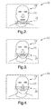
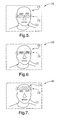
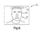
- Figs. 2-8 Examples of images captured by camera 18 are shown in Figs. 2-8.
- image 30 shown in Fig. 2, the majority of the image includes face 23 of occupant's head 24.
- Band of light 20 is shown as the shaded area, however in the actual image, band of light 20 may be a brightened or illuminated area.
- band of light 20 illuminates a chin area of face 23 and appears in a lower portion of image 30.
- the shaded area corresponding to band of light 20 appears at progressively higher positions in the aforementioned images.
- Processor 16 determines distance Z between face 23 of occupant's head 24 and camera 18 by measuring the vertical height or distance of the appearance of band of light 20 in images captured by camera 18.
- band of light 20 when occupant's head 24 is present in the image such as images 30 and 42, the appearance of band of light 20 appears higher such as image 42 or lower such as image 30, depending on distance Z between face 23 of occupant's head 24 and camera 18.
- the higher the appearance of light band 20 in the image indicates a smaller distance Z.
- An angle (not shown) between band or plane of light 20 (in Fig. 1) and the central axis of field of view 22 of camera 18 translates changes in distance Z into changes of the vertical position of the appearance of band of light 20 (in Fig. 2) in the images captured by camera 18.
- the angle between the band of light 20 and the central axis of field of view 22 of camera 18 is generally greater than 10 degrees.
- imaging such as binarizing the images and determining the center of mass of bright area corresponding to band of light 20 in the image may be used by processor 16.
- the center of mass of the bright area of each image is positioned at a distance of Y pixels from the upper or lower edge of the image.
- a linear model such as Equation 1, shown below, may be used by processor 16 to relate distance Z and vertical pixel distance Y.
- Z K * Y + N
- the constants K and N may be determined from the physical dimensions of the automobile and occupant monitoring system 10 or by conducting experimental testing in which distance Z is measured for several different values of Y.
- the experiment data may then be input into the classical Least Squares method to determine constants K and N or used to create a look up table.
- Examples of other models that may be used to determine constants K and N include using a piecewise linear model and applying classical Least Squares to each piece and Nonlinear Least Squares.
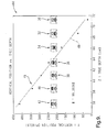
- Fig. 9 includes chart 44 depicting experimental data from testing in which distance Z was measured for seven different values of Y.
- Chart 44 illustrates the vertical pixel position or distance Y on the y-axis and the true depth or measured distance Z between camera 18 and face 23 of occupant's head 24 in centimeters.
- Data set 46 includes an illustration of the corresponding images 42, 40, 38, 36, 34, 32, and 30, discussed above, indicating the vertical position of the appearance of band of light 20 in the respective images.
- Trend line 48 was determined for data set 46 having a relatively high R value (99.3036%) indicating that relationship between Y and Z is relatively linear.
- Constants K and N may be calculated using the equation corresponding to trend line 48 as an empirical correlation.
Landscapes
- Engineering & Computer Science (AREA)
- Mechanical Engineering (AREA)
- Theoretical Computer Science (AREA)
- General Health & Medical Sciences (AREA)
- Human Computer Interaction (AREA)
- Physics & Mathematics (AREA)
- General Physics & Mathematics (AREA)
- Multimedia (AREA)
- Health & Medical Sciences (AREA)
- Oral & Maxillofacial Surgery (AREA)
- Computer Vision & Pattern Recognition (AREA)
- Air Bags (AREA)
- Length Measuring Devices By Optical Means (AREA)
- Stereoscopic And Panoramic Photography (AREA)
- Measurement Of Optical Distance (AREA)
- Length Measuring Devices With Unspecified Measuring Means (AREA)
- Traffic Control Systems (AREA)
- Fittings On The Vehicle Exterior For Carrying Loads, And Devices For Holding Or Mounting Articles (AREA)
Applications Claiming Priority (1)
| Application Number | Priority Date | Filing Date | Title |
|---|---|---|---|
| US11/318,294 US20070146482A1 (en) | 2005-12-23 | 2005-12-23 | Method of depth estimation from a single camera |
Publications (2)
| Publication Number | Publication Date |
|---|---|
| EP1800964A1 true EP1800964A1 (de) | 2007-06-27 |
| EP1800964B1 EP1800964B1 (de) | 2010-03-17 |
Family
ID=37907424
Family Applications (1)
| Application Number | Title | Priority Date | Filing Date |
|---|---|---|---|
| EP06077250A Active EP1800964B1 (de) | 2005-12-23 | 2006-12-14 | Verfahren zur Tiefenschätzung von einer Einzelkamera aus |
Country Status (4)
| Country | Link |
|---|---|
| US (1) | US20070146482A1 (de) |
| EP (1) | EP1800964B1 (de) |
| AT (1) | ATE461081T1 (de) |
| DE (1) | DE602006012923D1 (de) |
Cited By (1)
| Publication number | Priority date | Publication date | Assignee | Title |
|---|---|---|---|---|
| EP2193421A4 (de) * | 2007-09-20 | 2011-03-30 | Volvo Lastvagnar Ab | Positionsdetektionsanordnung und betriebsverfahren für eine positionsdetektionsanordnung |
Families Citing this family (4)
| Publication number | Priority date | Publication date | Assignee | Title |
|---|---|---|---|---|
| US20140098232A1 (en) * | 2011-06-17 | 2014-04-10 | Honda Motor Co., Ltd. | Occupant sensing device |
| US9710958B2 (en) * | 2011-11-29 | 2017-07-18 | Samsung Electronics Co., Ltd. | Image processing apparatus and method |
| JP7228982B2 (ja) * | 2018-09-26 | 2023-02-27 | 株式会社Subaru | 車両の乗員保護システム |
| CN111376254B (zh) * | 2018-12-29 | 2023-12-29 | 上海晨兴希姆通电子科技有限公司 | 平面测距方法及系统和机械手调校平面的方法及系统 |
Citations (8)
| Publication number | Priority date | Publication date | Assignee | Title |
|---|---|---|---|---|
| EP1033290A2 (de) | 1999-03-01 | 2000-09-06 | Delphi Technologies, Inc. | Infrarot-Belegungserkennungsvorrichtung in einem Kraftfahrzeug sowie Verfahren |
| EP1049046A1 (de) * | 1999-04-23 | 2000-11-02 | Siemens Aktiengesellschaft | Verfahren und Vorrichtung zur Ermittlung der Position eines Objektes innerhalb einer Szene |
| US20030079929A1 (en) | 2001-10-31 | 2003-05-01 | Akira Takagi | Apparatus for detecting head of occupant in vehicle |
| WO2003059697A1 (en) | 2002-01-16 | 2003-07-24 | Autoliv Development Ab | A camera arrangement |
| WO2003066386A2 (en) * | 2002-02-02 | 2003-08-14 | Qinetiq Limited | Head position sensor |
| US20040085448A1 (en) | 2002-10-22 | 2004-05-06 | Tomoyuki Goto | Vehicle occupant detection apparatus for deriving information concerning condition of occupant of vehicle seat |
| US20040153229A1 (en) | 2002-09-11 | 2004-08-05 | Gokturk Salih Burak | System and method for providing intelligent airbag deployment |
| WO2004101325A1 (de) * | 2003-05-13 | 2004-11-25 | Siemens Aktiengesellschaft | Verfahren zur bestimmung der aktuellen kopfposition von fahrzeuginsassen |
Family Cites Families (10)
| Publication number | Priority date | Publication date | Assignee | Title |
|---|---|---|---|---|
| US6820897B2 (en) * | 1992-05-05 | 2004-11-23 | Automotive Technologies International, Inc. | Vehicle object detection system and method |
| US5446661A (en) * | 1993-04-15 | 1995-08-29 | Automotive Systems Laboratory, Inc. | Adjustable crash discrimination system with occupant position detection |
| JP3293308B2 (ja) * | 1994-03-10 | 2002-06-17 | 三菱電機株式会社 | 人物状態検出装置 |
| JP3909377B2 (ja) * | 1997-02-14 | 2007-04-25 | 株式会社安川電機 | 屋外用距離計測装置 |
| DE10063380B4 (de) * | 2000-12-19 | 2005-06-09 | Heraeus Med Gmbh | Verfahren und Vorrichtung zur Video-Aufnahme eines beleuchteten Feldes |
| US6927694B1 (en) * | 2001-08-20 | 2005-08-09 | Research Foundation Of The University Of Central Florida | Algorithm for monitoring head/eye motion for driver alertness with one camera |
| JP2004020247A (ja) * | 2002-06-13 | 2004-01-22 | Mitsubishi Electric Corp | 乗員検出装置 |
| US7379559B2 (en) * | 2003-05-28 | 2008-05-27 | Trw Automotive U.S. Llc | Method and apparatus for determining an occupant's head location in an actuatable occupant restraining system |
| US8824730B2 (en) * | 2004-01-09 | 2014-09-02 | Hewlett-Packard Development Company, L.P. | System and method for control of video bandwidth based on pose of a person |
| US7334924B2 (en) * | 2005-06-09 | 2008-02-26 | Delphi Technologies, Inc. | Illumination apparatus for an optical occupant monitoring system in a vehicle |
-
2005
- 2005-12-23 US US11/318,294 patent/US20070146482A1/en not_active Abandoned
-
2006
- 2006-12-14 AT AT06077250T patent/ATE461081T1/de not_active IP Right Cessation
- 2006-12-14 EP EP06077250A patent/EP1800964B1/de active Active
- 2006-12-14 DE DE602006012923T patent/DE602006012923D1/de active Active
Patent Citations (8)
| Publication number | Priority date | Publication date | Assignee | Title |
|---|---|---|---|---|
| EP1033290A2 (de) | 1999-03-01 | 2000-09-06 | Delphi Technologies, Inc. | Infrarot-Belegungserkennungsvorrichtung in einem Kraftfahrzeug sowie Verfahren |
| EP1049046A1 (de) * | 1999-04-23 | 2000-11-02 | Siemens Aktiengesellschaft | Verfahren und Vorrichtung zur Ermittlung der Position eines Objektes innerhalb einer Szene |
| US20030079929A1 (en) | 2001-10-31 | 2003-05-01 | Akira Takagi | Apparatus for detecting head of occupant in vehicle |
| WO2003059697A1 (en) | 2002-01-16 | 2003-07-24 | Autoliv Development Ab | A camera arrangement |
| WO2003066386A2 (en) * | 2002-02-02 | 2003-08-14 | Qinetiq Limited | Head position sensor |
| US20040153229A1 (en) | 2002-09-11 | 2004-08-05 | Gokturk Salih Burak | System and method for providing intelligent airbag deployment |
| US20040085448A1 (en) | 2002-10-22 | 2004-05-06 | Tomoyuki Goto | Vehicle occupant detection apparatus for deriving information concerning condition of occupant of vehicle seat |
| WO2004101325A1 (de) * | 2003-05-13 | 2004-11-25 | Siemens Aktiengesellschaft | Verfahren zur bestimmung der aktuellen kopfposition von fahrzeuginsassen |
Cited By (1)
| Publication number | Priority date | Publication date | Assignee | Title |
|---|---|---|---|---|
| EP2193421A4 (de) * | 2007-09-20 | 2011-03-30 | Volvo Lastvagnar Ab | Positionsdetektionsanordnung und betriebsverfahren für eine positionsdetektionsanordnung |
Also Published As
| Publication number | Publication date |
|---|---|
| US20070146482A1 (en) | 2007-06-28 |
| EP1800964B1 (de) | 2010-03-17 |
| DE602006012923D1 (de) | 2010-04-29 |
| ATE461081T1 (de) | 2010-04-15 |
Similar Documents
| Publication | Publication Date | Title |
|---|---|---|
| US12412302B2 (en) | Systems, devices and methods for measuring the mass of objects in a vehicle | |
| US11706377B2 (en) | Visual, depth and micro-vibration data extraction using a unified imaging device | |
| EP3259734B1 (de) | Verminderung von blendung | |
| JP5753509B2 (ja) | 被測定物情報取得装置 | |
| US9340156B2 (en) | Method for detecting an object in an environmental region of a motor vehicle by means of a camera system of the motor vehicle, camera system and motor vehicle | |
| EP2918225A1 (de) | Vorrichtung zur messung biologischer informationen und eingabevorrichtung damit | |
| EP3075304A1 (de) | Blickrichtungsdetektions-hilfsvorrichtung und blickrichtungsdetektions-hilfsverfahren | |
| EP2976990B1 (de) | Pupillenerkennungsvorrichtung und pupillenerkennungsverfahren | |
| JP2008518195A (ja) | 乗員検出システム | |
| EP3011894B1 (de) | Blickdetektionsvorrichtung und blickdetektionsverfahren | |
| JP2003194528A5 (de) | ||
| US10579867B2 (en) | Method and device for detecting an object in a vehicle | |
| US10118534B2 (en) | Irradiation apparatus | |
| JP2003002138A (ja) | 車載後方監視方法およびその装置 | |
| US10057500B2 (en) | Image capturing method and monitoring apparatus with supplemental lighting modulation | |
| US20200324696A1 (en) | Lighting control system and lighting control method | |
| EP1800964A1 (de) | Verfahren zur Tiefenschätzung von einer Einzelkamera aus | |
| EP3878373B1 (de) | Beurteilungsvorrichtung, beurteilungsverfahren und beurteilungsprogramm | |
| US20060050927A1 (en) | Camera arrangement | |
| JP2013123180A (ja) | モニタリング装置 | |
| JP2009303192A (ja) | 顔検出システム | |
| JP2001213268A (ja) | 車両用エアバッグシステムのための乗員判定装置 | |
| DE102022121815A1 (de) | Verfahren und Vorrichtung zum Betreiben eines Innenraum-Trackingsystems in einem Fahrzeug | |
| JP2022053216A (ja) | 車両内状態検知装置 | |
| JPS6177704A (ja) | 車両運転者位置認識装置 |
Legal Events
| Date | Code | Title | Description |
|---|---|---|---|
| PUAI | Public reference made under article 153(3) epc to a published international application that has entered the european phase |
Free format text: ORIGINAL CODE: 0009012 |
|
| AK | Designated contracting states |
Kind code of ref document: A1 Designated state(s): AT BE BG CH CY CZ DE DK EE ES FI FR GB GR HU IE IS IT LI LT LU LV MC NL PL PT RO SE SI SK TR |
|
| AX | Request for extension of the european patent |
Extension state: AL BA HR MK YU |
|
| 17P | Request for examination filed |
Effective date: 20071227 |
|
| 17Q | First examination report despatched |
Effective date: 20080207 |
|
| AKX | Designation fees paid |
Designated state(s): AT BE BG CH CY CZ DE DK EE ES FI FR GB GR HU IE IS IT LI LT LU LV MC NL PL PT RO SE SI SK TR |
|
| GRAP | Despatch of communication of intention to grant a patent |
Free format text: ORIGINAL CODE: EPIDOSNIGR1 |
|
| GRAS | Grant fee paid |
Free format text: ORIGINAL CODE: EPIDOSNIGR3 |
|
| GRAA | (expected) grant |
Free format text: ORIGINAL CODE: 0009210 |
|
| AK | Designated contracting states |
Kind code of ref document: B1 Designated state(s): AT BE BG CH CY CZ DE DK EE ES FI FR GB GR HU IE IS IT LI LT LU LV MC NL PL PT RO SE SI SK TR |
|
| REG | Reference to a national code |
Ref country code: GB Ref legal event code: FG4D |
|
| REG | Reference to a national code |
Ref country code: CH Ref legal event code: EP |
|
| REG | Reference to a national code |
Ref country code: IE Ref legal event code: FG4D |
|
| REF | Corresponds to: |
Ref document number: 602006012923 Country of ref document: DE Date of ref document: 20100429 Kind code of ref document: P |
|
| REG | Reference to a national code |
Ref country code: NL Ref legal event code: VDEP Effective date: 20100317 |
|
| PG25 | Lapsed in a contracting state [announced via postgrant information from national office to epo] |
Ref country code: LT Free format text: LAPSE BECAUSE OF FAILURE TO SUBMIT A TRANSLATION OF THE DESCRIPTION OR TO PAY THE FEE WITHIN THE PRESCRIBED TIME-LIMIT Effective date: 20100317 |
|
| LTIE | Lt: invalidation of european patent or patent extension |
Effective date: 20100317 |
|
| PG25 | Lapsed in a contracting state [announced via postgrant information from national office to epo] |
Ref country code: SI Free format text: LAPSE BECAUSE OF FAILURE TO SUBMIT A TRANSLATION OF THE DESCRIPTION OR TO PAY THE FEE WITHIN THE PRESCRIBED TIME-LIMIT Effective date: 20100317 Ref country code: LV Free format text: LAPSE BECAUSE OF FAILURE TO SUBMIT A TRANSLATION OF THE DESCRIPTION OR TO PAY THE FEE WITHIN THE PRESCRIBED TIME-LIMIT Effective date: 20100317 Ref country code: PL Free format text: LAPSE BECAUSE OF FAILURE TO SUBMIT A TRANSLATION OF THE DESCRIPTION OR TO PAY THE FEE WITHIN THE PRESCRIBED TIME-LIMIT Effective date: 20100317 Ref country code: AT Free format text: LAPSE BECAUSE OF FAILURE TO SUBMIT A TRANSLATION OF THE DESCRIPTION OR TO PAY THE FEE WITHIN THE PRESCRIBED TIME-LIMIT Effective date: 20100317 Ref country code: FI Free format text: LAPSE BECAUSE OF FAILURE TO SUBMIT A TRANSLATION OF THE DESCRIPTION OR TO PAY THE FEE WITHIN THE PRESCRIBED TIME-LIMIT Effective date: 20100317 |
|
| PG25 | Lapsed in a contracting state [announced via postgrant information from national office to epo] |
Ref country code: ES Free format text: LAPSE BECAUSE OF FAILURE TO SUBMIT A TRANSLATION OF THE DESCRIPTION OR TO PAY THE FEE WITHIN THE PRESCRIBED TIME-LIMIT Effective date: 20100628 Ref country code: EE Free format text: LAPSE BECAUSE OF FAILURE TO SUBMIT A TRANSLATION OF THE DESCRIPTION OR TO PAY THE FEE WITHIN THE PRESCRIBED TIME-LIMIT Effective date: 20100317 Ref country code: CY Free format text: LAPSE BECAUSE OF FAILURE TO SUBMIT A TRANSLATION OF THE DESCRIPTION OR TO PAY THE FEE WITHIN THE PRESCRIBED TIME-LIMIT Effective date: 20100317 Ref country code: BE Free format text: LAPSE BECAUSE OF FAILURE TO SUBMIT A TRANSLATION OF THE DESCRIPTION OR TO PAY THE FEE WITHIN THE PRESCRIBED TIME-LIMIT Effective date: 20100317 Ref country code: GR Free format text: LAPSE BECAUSE OF FAILURE TO SUBMIT A TRANSLATION OF THE DESCRIPTION OR TO PAY THE FEE WITHIN THE PRESCRIBED TIME-LIMIT Effective date: 20100618 Ref country code: NL Free format text: LAPSE BECAUSE OF FAILURE TO SUBMIT A TRANSLATION OF THE DESCRIPTION OR TO PAY THE FEE WITHIN THE PRESCRIBED TIME-LIMIT Effective date: 20100317 Ref country code: RO Free format text: LAPSE BECAUSE OF FAILURE TO SUBMIT A TRANSLATION OF THE DESCRIPTION OR TO PAY THE FEE WITHIN THE PRESCRIBED TIME-LIMIT Effective date: 20100317 Ref country code: SE Free format text: LAPSE BECAUSE OF FAILURE TO SUBMIT A TRANSLATION OF THE DESCRIPTION OR TO PAY THE FEE WITHIN THE PRESCRIBED TIME-LIMIT Effective date: 20100317 |
|
| PG25 | Lapsed in a contracting state [announced via postgrant information from national office to epo] |
Ref country code: IS Free format text: LAPSE BECAUSE OF FAILURE TO SUBMIT A TRANSLATION OF THE DESCRIPTION OR TO PAY THE FEE WITHIN THE PRESCRIBED TIME-LIMIT Effective date: 20100717 Ref country code: SK Free format text: LAPSE BECAUSE OF FAILURE TO SUBMIT A TRANSLATION OF THE DESCRIPTION OR TO PAY THE FEE WITHIN THE PRESCRIBED TIME-LIMIT Effective date: 20100317 Ref country code: BG Free format text: LAPSE BECAUSE OF FAILURE TO SUBMIT A TRANSLATION OF THE DESCRIPTION OR TO PAY THE FEE WITHIN THE PRESCRIBED TIME-LIMIT Effective date: 20100617 Ref country code: CZ Free format text: LAPSE BECAUSE OF FAILURE TO SUBMIT A TRANSLATION OF THE DESCRIPTION OR TO PAY THE FEE WITHIN THE PRESCRIBED TIME-LIMIT Effective date: 20100317 |
|
| PLBE | No opposition filed within time limit |
Free format text: ORIGINAL CODE: 0009261 |
|
| STAA | Information on the status of an ep patent application or granted ep patent |
Free format text: STATUS: NO OPPOSITION FILED WITHIN TIME LIMIT |
|
| PG25 | Lapsed in a contracting state [announced via postgrant information from national office to epo] |
Ref country code: PT Free format text: LAPSE BECAUSE OF FAILURE TO SUBMIT A TRANSLATION OF THE DESCRIPTION OR TO PAY THE FEE WITHIN THE PRESCRIBED TIME-LIMIT Effective date: 20100719 Ref country code: DK Free format text: LAPSE BECAUSE OF FAILURE TO SUBMIT A TRANSLATION OF THE DESCRIPTION OR TO PAY THE FEE WITHIN THE PRESCRIBED TIME-LIMIT Effective date: 20100317 |
|
| 26N | No opposition filed |
Effective date: 20101220 |
|
| PG25 | Lapsed in a contracting state [announced via postgrant information from national office to epo] |
Ref country code: IT Free format text: LAPSE BECAUSE OF FAILURE TO SUBMIT A TRANSLATION OF THE DESCRIPTION OR TO PAY THE FEE WITHIN THE PRESCRIBED TIME-LIMIT Effective date: 20100317 |
|
| PG25 | Lapsed in a contracting state [announced via postgrant information from national office to epo] |
Ref country code: MC Free format text: LAPSE BECAUSE OF NON-PAYMENT OF DUE FEES Effective date: 20101231 |
|
| REG | Reference to a national code |
Ref country code: CH Ref legal event code: PL |
|
| GBPC | Gb: european patent ceased through non-payment of renewal fee |
Effective date: 20101214 |
|
| REG | Reference to a national code |
Ref country code: FR Ref legal event code: ST Effective date: 20110831 |
|
| PG25 | Lapsed in a contracting state [announced via postgrant information from national office to epo] |
Ref country code: IE Free format text: LAPSE BECAUSE OF NON-PAYMENT OF DUE FEES Effective date: 20101214 Ref country code: LI Free format text: LAPSE BECAUSE OF NON-PAYMENT OF DUE FEES Effective date: 20101231 Ref country code: FR Free format text: LAPSE BECAUSE OF NON-PAYMENT OF DUE FEES Effective date: 20110103 Ref country code: CH Free format text: LAPSE BECAUSE OF NON-PAYMENT OF DUE FEES Effective date: 20101231 |
|
| PG25 | Lapsed in a contracting state [announced via postgrant information from national office to epo] |
Ref country code: GB Free format text: LAPSE BECAUSE OF NON-PAYMENT OF DUE FEES Effective date: 20101214 |
|
| PG25 | Lapsed in a contracting state [announced via postgrant information from national office to epo] |
Ref country code: HU Free format text: LAPSE BECAUSE OF FAILURE TO SUBMIT A TRANSLATION OF THE DESCRIPTION OR TO PAY THE FEE WITHIN THE PRESCRIBED TIME-LIMIT Effective date: 20100918 Ref country code: LU Free format text: LAPSE BECAUSE OF NON-PAYMENT OF DUE FEES Effective date: 20101214 |
|
| PG25 | Lapsed in a contracting state [announced via postgrant information from national office to epo] |
Ref country code: TR Free format text: LAPSE BECAUSE OF FAILURE TO SUBMIT A TRANSLATION OF THE DESCRIPTION OR TO PAY THE FEE WITHIN THE PRESCRIBED TIME-LIMIT Effective date: 20100317 |
|
| REG | Reference to a national code |
Ref country code: DE Ref legal event code: R082 Ref document number: 602006012923 Country of ref document: DE Representative=s name: MANITZ FINSTERWALD PATENT- UND RECHTSANWALTSPA, DE Ref country code: DE Ref legal event code: R082 Ref document number: 602006012923 Country of ref document: DE Representative=s name: MANITZ FINSTERWALD PATENTANWAELTE PARTMBB, DE Ref country code: DE Ref legal event code: R081 Ref document number: 602006012923 Country of ref document: DE Owner name: APTIV TECHNOLOGIES LIMITED, BB Free format text: FORMER OWNER: DELPHI TECHNOLOGIES, INC., TROY, MICH., US |
|
| P01 | Opt-out of the competence of the unified patent court (upc) registered |
Effective date: 20230425 |
|
| REG | Reference to a national code |
Ref country code: DE Ref legal event code: R081 Ref document number: 602006012923 Country of ref document: DE Owner name: APTIV TECHNOLOGIES AG, CH Free format text: FORMER OWNER: APTIV TECHNOLOGIES LIMITED, ST. MICHAEL, BB |
|
| PGFP | Annual fee paid to national office [announced via postgrant information from national office to epo] |
Ref country code: DE Payment date: 20251117 Year of fee payment: 20 |