EP1801421A1 - Ventilateur et pale de ventilateur - Google Patents
Ventilateur et pale de ventilateur Download PDFInfo
- Publication number
- EP1801421A1 EP1801421A1 EP05028264A EP05028264A EP1801421A1 EP 1801421 A1 EP1801421 A1 EP 1801421A1 EP 05028264 A EP05028264 A EP 05028264A EP 05028264 A EP05028264 A EP 05028264A EP 1801421 A1 EP1801421 A1 EP 1801421A1
- Authority
- EP
- European Patent Office
- Prior art keywords
- fan
- edge
- fan blade
- outer edge
- wing
- Prior art date
- Legal status (The legal status is an assumption and is not a legal conclusion. Google has not performed a legal analysis and makes no representation as to the accuracy of the status listed.)
- Withdrawn
Links
- 230000007423 decrease Effects 0.000 description 4
- 239000000463 material Substances 0.000 description 4
- 230000002349 favourable effect Effects 0.000 description 3
- 230000006978 adaptation Effects 0.000 description 2
- 230000008901 benefit Effects 0.000 description 2
- 230000003247 decreasing effect Effects 0.000 description 2
- 210000001015 abdomen Anatomy 0.000 description 1
- 230000008859 change Effects 0.000 description 1
- 230000003111 delayed effect Effects 0.000 description 1
- 230000001419 dependent effect Effects 0.000 description 1
- 230000002045 lasting effect Effects 0.000 description 1
- 239000007788 liquid Substances 0.000 description 1
- 238000000034 method Methods 0.000 description 1
- 238000005457 optimization Methods 0.000 description 1
- 230000009467 reduction Effects 0.000 description 1
- 230000004044 response Effects 0.000 description 1
- 230000007704 transition Effects 0.000 description 1
- 238000011144 upstream manufacturing Methods 0.000 description 1
Images


Classifications
-
- F—MECHANICAL ENGINEERING; LIGHTING; HEATING; WEAPONS; BLASTING
- F04—POSITIVE - DISPLACEMENT MACHINES FOR LIQUIDS; PUMPS FOR LIQUIDS OR ELASTIC FLUIDS
- F04D—NON-POSITIVE-DISPLACEMENT PUMPS
- F04D29/00—Details, component parts, or accessories
- F04D29/26—Rotors specially for elastic fluids
- F04D29/32—Rotors specially for elastic fluids for axial flow pumps
- F04D29/38—Blades
- F04D29/384—Blades characterised by form
-
- F—MECHANICAL ENGINEERING; LIGHTING; HEATING; WEAPONS; BLASTING
- F04—POSITIVE - DISPLACEMENT MACHINES FOR LIQUIDS; PUMPS FOR LIQUIDS OR ELASTIC FLUIDS
- F04D—NON-POSITIVE-DISPLACEMENT PUMPS
- F04D29/00—Details, component parts, or accessories
- F04D29/26—Rotors specially for elastic fluids
- F04D29/32—Rotors specially for elastic fluids for axial flow pumps
- F04D29/325—Rotors specially for elastic fluids for axial flow pumps for axial flow fans
Definitions
- the invention relates to a fan and a fan blade.
- fluidically shaped fan blades provide high performance, e.g. with regard to the achieved flow-through volume or the discharge pressure.
- a problem is often a strong noise during operation of the fan.
- the DE 199 480 75 used to reduce the running noise an axial fan with wings having an S-shaped, leading edge of the wing with a protruding outer corner.
- the EP 887 558 B1 proposes fan blades with an S-shaped leading edge and a trailing edge mirrored to the leading edge.
- the US 3 416 725 shows a wing shape with a double-angled leading edge and a slightly simply sickled trailing edge.
- the DE 103 26 637 B3 describes a fan with alternating direction of rotation, which has wings with S-shaped, outwardly strongly receding leading edge.
- the WO 1998005868 discloses a numerical method for aeroacoustic optimization of an axial fan or its blade geometry.
- the US 2,649,921 provides a fan with very short and wide blades and triple-curved inflow and outflow edges.
- Last represents the FR 27 280 28 Wing with convex edges with large winglets.
- the invention deals with the problem of providing a low-noise fan or fan blades.
- the invention solves this problem with a fan or a fan blade according to the independent claims.
- the dependent claims contain advantageous embodiments.
- a fan according to the invention uses fan blades according to the invention as described below for moving the material surrounding the fan, such as air or another gas or even a fan Liquid.
- the hub forms the center of the fan.
- a radial jet is defined, which extends from the center of the hub centrally through the respective blade root of the fan blade to the outside.
- Each fan blade has a leading edge which, in operation, advances in the normal direction of travel and a trailing edge which lags in operation in the normal direction of travel.
- an operation of the described device is also possible with the opposite direction of rotation. Nevertheless, the inflow and outflow are usually only for one direction optimally shaped; operating in the opposite direction can not deliver optimal performance.
- “Inside” is the hub for a ventilator described, “outside” the housing or the shaft (if available, which is usually the case).
- the outer edge of the fan blade is therefore the edge furthest away from the hub; it is often shorter than the inflow and outflow edges.
- the fan blade sheet has a suction side, which sucks the incoming air, etc., during operation, and an opposite pressure side, on which the pressure for ejecting the air, etc. builds up.
- a fan according to the invention for this purpose uses at least one fan blade according to the invention, which it preferably arranges at equal intervals around a hub.
- the fan comprises fastening devices which receive, for example, a counterpart attached to the wing.
- the fan has a controllable motor, which provides for its operation, ie the rotation of the at least one fan blade about an imaginary axis through the center of the hub.
- the fan is in a shaft or housing.
- the fan blades according to the invention used by a fan according to the invention achieve the reduced noise generation during operation of the fan by means of a special edge shape.
- the leading edge of a wing according to the invention in the vane blade plane S-shaped that is, has two arches with a reversal point.
- the reversal point is preferably located approximately in the middle the leading edge; the arc lying on the outside from the turning point preferably bulges concavely into the wing surface, that is to say in the direction of the radial jet, while the arc lying inwardly from the turning point preferably convexly bulges away from the radial ray.
- the term "in the blade plane” is intended only to illustrate that the S-shape of the leading edge causes a bulge in the wing surface in and out of her and not about a vertical curvature. It should be noted, however, that in most embodiments of a fan blade according to the present invention, the individual points of the fan blade do not lie in one plane; Also, the individual points of the leading edge lie - no matter in which coordinate system - usually not on a straight line. In this respect, geometrically speaking, a "wing blade plane" is present in the rarest cases.
- a fan according to the invention avoids limitations that partially occur in conventional fans due to a curved edge shape.
- fans are attempted to minimize the flow of air from the pressure side to the suction side of the fan blades over their outer edges.
- preferably only the narrowest possible gap between the outer edge of a fan blade and a housing is preferably provided.
- the possibility should be ensured to adjust the fan blade rotated in adaptation to external conditions or user requests to the radial beam as a rotation axis. The adjustment is usually made before the fan is started, if the performance profile of the system is adapted to the specific application.
- the fan is equipped with a control unit and sensors or an operator display as well as actuators. Then, the control unit, for example, in response to the sensor signals or operator inputs with the help of the actuators constantly provide an optimal angle of rotation adjustment of the wings to the radial jet.
- leading edge or trailing edge often results in "faster” abutment with fewer degrees of rotation of at least one corner of the outer edge of the housing with the same gap width between the housing and outer edge as compared to (more or less) straight leading or trailing edges.
- the invention prevents this disadvantage by the special S-shape of the leading edge.
- This ensures namely that the center of the outer edge of a fan blade according to the invention as on a non-curved wing on the axis of rotation.
- the term "center point” refers to the point of intersection of two outer edge lines, one of which is located on the outer edge "Leading edge” of the outer edge (ie where the leading edge and the outer edge meet) to the rear "outflow" end (where the outer edge and the trailing edge meet) and at any point the same distance to a long side edge the outer edge (where the suction side (or pressure side) of the blade and the outer edge meet) as the other, while the other line connects the center of the long side edges of the outer edge and also at each point in the middle between the " Run-up and outflow ends.
- center of the outer edge is contemplated, the use of which provides a similar result in terms of rotatability.
- Other embodiments allow for an inaccurate determination of the center of the outer edge (for example, by a bare gauge).
- the fan blade with the same gap width remains as far as a comparable non-curved wing about its radial beam rotatable (if it is mounted correspondingly rotatable); the invention combines the advantage of noise reduction with the advantage of variable adjustability.
- the trailing edge In adaptation to the shape of the leading edge and the fixed position of the outer edge, the following embodiments of the invention propose a flow-mechanically favorable shape of the trailing edge.
- the trailing edge also forms at least one arc in the "vane leaf plane", but in most embodiments, two or three arcs, but often only one arc is curved in a similarly strong manner as in the leading edge.
- the highly developed arc lies in the outer third of the trailing edge and has a curvature parallel to the outer arc of the leading edge.
- two flat arches are housed with a reversal point. The second arc then goes over very flat and with another reversal point in the outer, parallel to the leading edge arc.
- the widest point of the fan blade so the point at which the inflow and Trailing edge furthest apart, in its inner fifth.
- the innermost point of the leading and trailing edge marks the widest point.
- the outer edge is the narrowest part of the wing.
- the outer edge of the fan blade according to the invention preferably conforms to the shape of a duct or housing around the fan (if it is in such a case) by absorbing the curvature of the circle formed by the cross section of the housing. If the outer edge is viewed from the outside in the direction of the radial jet, its front end meeting the leading edge and its rear end meeting the trailing edge preferably have a rounded shape between the suction and the pressure side, wherein the radius of the rounding at the front "Anström"
- the outer edge width in the area of the first third of the outer edge first increases and then decreases more slowly from the "inflow" end in the direction of the "outflow” end
- the increase in the outer edge width is mainly achieved by the bulging of a long side edge of the outer edge (usually the one which hits the suction side of the fan blade)
- This convex curvature "wing shape” enhances the speed difference between the suction and pressure sides and the amount of air deflection the profiles of parallel to the outer edge cuts of the
- a cross piece or winglet is attached to the entire length of the outer edge or even beyond the length.
- a crosspiece helps to reduce or eliminate air vortices that often form at the end of the wing. It is perpendicular to the radial from both sides, with the two angles to the wing surface depending on their curvature along the radial beam often differ significantly from 90 °, but together give approximately 180 °.
- Another embodiment provides an obliquely outward and the sucked air opposing crosspiece.
- the crosspiece - seen from the outside - increases the width of the outer edge to twice to three times.
- the crosspiece is usually the same distance in both directions beyond the width of the outer edge.
- the width changes from one vertex of the outer edge to the other, with an increase up to the middle of the outer edge and then a decrease in the width. Accordingly, at the ends of the outer edge, the smallest width of the cross piece is present, which, however, usually exceeds the width of the outer edge.
- Another embodiment does not provide for exceeding the width of the outer edge at its ends.
- the variants with decreasing width of the crosspiece to the ends of the outer edge prove to be particularly favorable for the adjustable range of rotation of the wing to the radial because they provide little additional material to be considered at the end of the outer edge endangered with respect to a bumping on the housing wall.
- a further specific embodiment takes into account the significant influence of the flow field in the fan, which can cause the sickling of a fan blade according to the invention: for example, the radial velocities and thus the distribution of the wing load along the radius change, etc.
- this embodiment sees a special structure of the Fan blades in front.
- the fan blade sheet has a curvature along the radial jet, so that the blade preferably bulges convexly on its suction side, concaved on the pressure side. This curvature is usually particularly pronounced in the outer half of the wing.
- a further curvature across its width there is a further curvature across its width.
- the individual points of the inner and outer edge are not on a straight line.
- the wing area is near the leading edge over its Whole length of the sucked air curved away, so that the inner and outer edge in the direction of their "inflow" end have such a curvature.
- the curvature across the width of the wing differs in most embodiments in the profiles of sections made at different locations of the radial jet parallel to the inner or outer edge, that is, changes over the length of the wing.
- This complex shape of a fan blade according to the invention proves to be favorable in terms of flow mechanics and prevents a performance drop, possibly caused by the sickle shape, which could otherwise occur compared to conventional blades with more or less straight edges. On the contrary, the same inflow, outflow and circulating conditions can result for such a wing according to the invention as for a comparable conventional wing.
- An inventive fan blade measures in length, for example, 1.5 to 4 times its maximum width, which thus exceeds the width significantly.
- the width varies considerably in some embodiments; For example, the width at different locations of the wing may differ by a factor of two.
- the absolute sash size is scaled depending on the desired delivery volume.
- the invention provides a fan and fan blades, which maintains high flexibility with low noise during operation. Furthermore, the invention proposes a special shape, which ensures high performance of the fan equipped with such fan blades.
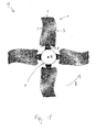
- FIG. 1 shows a fan 9 from the printing direction.
- the fan 9 has four star-shaped arranged around the hub 7 fan blades 1, of which according to the viewing direction in each case the pressure side can be seen.
- the wing feet 5 of the fan blades 1 For attachment to the hub mounted fasteners 8, the wing feet 5 of the fan blades 1 on.
- the wing feet 5 are placed in the fasteners 8 and then rotated by the radial until they have reached the desired rotational position.
- the fixing in the selected position is achieved, for example, by means of screws, clamping devices such as springs or by means of adjustable or adjusted intermediate pieces (which are not shown) inserted between the fan blade base 5 and fastening device 8.
- the form of attachment are the (partially considerable) centrifugal forces that act on the fan blades 1 during operation.
- the motor which sets the fan 9 in a rotational movement about an axis projecting through the center N of the hub 7 from the image plane axis.
- the normal direction of movement of the fan 9 indicates arrow B.
- the shape of the wings 1 is optimized. However, if necessary, a movement in the other direction is possible.
- a fan 9 may comprise any other even or odd number of fan blades 1, which are usually arranged at the same distance from each other.
- the leading edge 2 shows the pressure side of a true-to-scale embodiment of a fan blade 1.
- the leading edge 2, which voraneilt in operation, has a flat S-shape, with the turning point seen from the inside is not quite in the middle of the leading edge 2.
- the trailing edge 3 is curved. In the outer third, it runs parallel to the leading edge; in the two inner thirds it shows two small, hardly pronounced bends with two reversal points.
- the corners of the inner edge 6 are slightly pulled down relative to the other edge points, so that the inner edge 6 describes a total in the image downwardly open curvature, the blade foot 5 interrupts in the middle.
- the blade root 5 is designed to connect the fan blade 1 with the fastening device 8 attached to the hub 7 (see FIG. 1) and to set the desired rotational position about the radial jet x.
- the radial jets x of the individual wings 1 extend from the center of the hub N of the fan 9 centrally through the wing base 5 of the respective wing 1 star-shaped outward.
- Center point (M) of the outer edge 4 of the fan blade 1 falls on the radial beam x as a rotation axis for the wing twisting.
- the ends of the outer edge 4 move in rotation about the rotation axis x on a circle with the distance of the end of the center M as a radius.
- the outer edge 4 also has a slight curvature to conform to the shape of the housing (not shown).
- the width of the fan blade decreases on the whole from the inside to the outer edge 4 to the outside.
- the widest wing point is not at the innermost point, but slightly shifted outwards; it measures about 7 cm.
- the wing 1 has a width of about 5.5 cm.
- the ratio of the length of the fan blade 1 moves to its width in the order of 1.8 to 2.4.
- the size of the wing 1 can be scaled down or enlarged in scale depending on the delivery volume become.
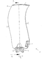
- Figure 3 illustrates a further embodiment of a fan blade 1 according to the invention in a side view of the trailing edge 3; in the picture, the suction side of the wing 1 is right.
- the curvature of the wing 1 along the radial beam x is clearly visible: the suction side of the wing bulges convex, the opposite pressure side concave.
- the inner edge 6 is significantly curved in comparison to the outer edge 4 of the sucked air.
- the wing 1 shown also has a crosspiece (winglet) 10. It is placed on the outer edge 4 and is equal to the suction and the pressure side beyond this.
- the angle between the protruding to the pressure side crosspiece part and the Leaf blade is due to the wing curvature significantly more than 90 °, while the angle between the protruding to the suction side crosspiece part and the blade is significantly lower.
- FIG. 4 shows the suction side of a further embodiment of a fan blade 1 from a slightly lateral perspective.
- this wing 1 has a crosspiece 10, which - as can be seen here - terminates with the length of the outer edge 4 and does not protrude beyond this.
- the slot 11 which serves as a recording for balancing weights when needed.
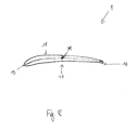
- Figure 5 presents a section of the wing 1 of Figure 4 along the axis A-A.
- the material thickness remains fairly constant in this embodiment over most of the wing length. Only in the outer third does it decrease significantly, since there lower forces act as in the inner wing part. Preferably, the material thickness is not constant with respect to further sectional profiles parallel to the section shown.
- FIG. 6 which shows a wing 1 seen from the hub to the outside, once again illustrates the complex structure of a wing according to the invention 1. Not only has the leading edge 2 an S-shape, but the wing 1 is also in the direction of Radial beam x curved inside out. Furthermore, the wing 1 also shows a curvature over its width, as can be seen on the inner edge 6. The end of the inner edge 6, which meets the trailing edge 3 is pronounced projecting in this embodiment.
- the crosspiece 10 It runs over the entire length of the outer edge 4, but closes off with the leading edge 2 and is not beyond this.
- a shallow drop from the "normal" width of the crosspiece 10 is provided up to the width of the leading edge.
- the crosspiece 10 multiplies the Width of the outer edge, for example, by a factor of 3.
- the shape of the protruding to the suction side crosspiece part differs from the shape of the protruding to the pressure side crosspiece part, which is made wider.
- the blade base 5 in this embodiment has a partially perforated circular ring on which, for example, a matching (not shown) adapter can be placed.
- a fastening device 8 on the hub 7 in turn receives the intermediate piece and thus ensures a firm hold of the wing 1.
- the choice or setting of the intermediate piece specifies the rotational position of the wing 1.
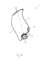
- Figure 7 shows the suction side of another embodiment of a fan blade according to the invention.
- the curvature of the wing 1 along the radial ray x is clearly visible, which is visible on the suction side as a convex "belly”.
- This embodiment also has a wing base 5 described with reference to FIG. 6 and a crosspiece 10.
- FIG. 8 shows the outer edge 4 of an embodiment of a fan blade 1, viewed from the outside in the direction of the radial jet. From this point of view, the wing shape of the outer edge 4 can be seen.
- the inflow end 15 of the outer edge, at which the leading edge meets the outer edge, as well as the opposite outflow end 16 has a rounded shape.
- the radius of the rounding is significantly greater at the inflow end 15 than at the outlet end 16.
- the suction side of the wing 1 and the outer edge meet, on the side edge 17, the pressure side and the outer edge. Due to the wing shape of the outer edge 4, the side edge 18 is longer than the side edge 17.
Landscapes
- Engineering & Computer Science (AREA)
- Mechanical Engineering (AREA)
- General Engineering & Computer Science (AREA)
- Structures Of Non-Positive Displacement Pumps (AREA)
Priority Applications (5)
| Application Number | Priority Date | Filing Date | Title |
|---|---|---|---|
| EP05028264A EP1801421A1 (fr) | 2005-12-22 | 2005-12-22 | Ventilateur et pale de ventilateur |
| EP06003819.7A EP1801422B1 (fr) | 2005-12-22 | 2006-02-24 | Ventilateur et aube de ventilateur |
| ES06003819T ES2427151T3 (es) | 2005-12-22 | 2006-02-24 | Ventilador y pala de ventilador |
| DK06003819T DK1801422T3 (da) | 2005-12-22 | 2006-02-24 | Ventilator og ventilatorvinge |
| US11/614,598 US20070201982A1 (en) | 2005-12-22 | 2006-12-21 | Ventilator and ventilator blade |
Applications Claiming Priority (1)
| Application Number | Priority Date | Filing Date | Title |
|---|---|---|---|
| EP05028264A EP1801421A1 (fr) | 2005-12-22 | 2005-12-22 | Ventilateur et pale de ventilateur |
Publications (1)
| Publication Number | Publication Date |
|---|---|
| EP1801421A1 true EP1801421A1 (fr) | 2007-06-27 |
Family
ID=36588777
Family Applications (1)
| Application Number | Title | Priority Date | Filing Date |
|---|---|---|---|
| EP05028264A Withdrawn EP1801421A1 (fr) | 2005-12-22 | 2005-12-22 | Ventilateur et pale de ventilateur |
Country Status (3)
| Country | Link |
|---|---|
| EP (1) | EP1801421A1 (fr) |
| DK (1) | DK1801422T3 (fr) |
| ES (1) | ES2427151T3 (fr) |
Cited By (3)
| Publication number | Priority date | Publication date | Assignee | Title |
|---|---|---|---|---|
| CN102261349A (zh) * | 2011-08-24 | 2011-11-30 | 张家港施亿百机电设备有限公司 | 轴流叶片 |
| CN113217460A (zh) * | 2020-01-21 | 2021-08-06 | 马勒国际有限公司 | 风扇叶轮 |
| CN114704490A (zh) * | 2022-04-13 | 2022-07-05 | 欧普照明股份有限公司 | 扇叶结构及风扇灯 |
Citations (14)
| Publication number | Priority date | Publication date | Assignee | Title |
|---|---|---|---|---|
| US2382535A (en) * | 1943-01-26 | 1945-08-14 | Buffalo Forge Co | Axial flow fan |
| US2649921A (en) | 1949-05-10 | 1953-08-25 | Guy S Faber | Propeller for fluid |
| US3416725A (en) | 1967-10-12 | 1968-12-17 | Acme Engineering And Mfg Corp | Dihedral bladed ventilating fan |
| DE7139398U (de) * | 1971-10-19 | 1972-05-31 | Benzing Ventilatoren Ohg | Axialflügelrad zum Fördern oder Absaugen von Luft bzw. Gasen |
| GB2291134A (en) * | 1994-07-02 | 1996-01-17 | Nuaire Ltd | Fan assembly |
| FR2728028A1 (fr) | 1994-12-07 | 1996-06-14 | Sardou Max | Dispositif pour transformer l'energie mecanique d'un moteur en une mise sous pression d'un gaz |
| WO1998005868A1 (fr) | 1996-08-01 | 1998-02-12 | Deutsches Zentrum für Luft- und Raumfahrt e.V. | Procede d'optimisation aeroacoustique d'un ventilateur axial |
| EP0992693A1 (fr) * | 1998-10-08 | 2000-04-12 | GATE S.p.A. | Ventilateur axial |
| DE19948075A1 (de) | 1998-10-08 | 2000-05-25 | Gate Spa | Axial-Lüfterrad, insbesondere für Motorfahrzeuge |
| US20030095864A1 (en) * | 2001-11-19 | 2003-05-22 | Borislav Ivanovic | Fan with reduced noise |
| EP0887558B1 (fr) | 1997-06-27 | 2004-02-18 | Siemens VDO Automotive Inc. | Ventilateur axial |
| DE102004017727A1 (de) * | 2003-04-19 | 2004-11-04 | Ebm-Papst St. Georgen Gmbh & Co. Kg | Lüfter |
| DE10326637B3 (de) | 2003-06-11 | 2005-01-13 | Bayerische Motoren Werke Ag | Kühlvorrichtung für ein Kraftfahrzeug |
| EP1577562A2 (fr) * | 2004-03-19 | 2005-09-21 | Halla Climate Control Corporation | Ventilateur axial |
-
2005
- 2005-12-22 EP EP05028264A patent/EP1801421A1/fr not_active Withdrawn
-
2006
- 2006-02-24 DK DK06003819T patent/DK1801422T3/da active
- 2006-02-24 ES ES06003819T patent/ES2427151T3/es not_active Expired - Lifetime
Patent Citations (14)
| Publication number | Priority date | Publication date | Assignee | Title |
|---|---|---|---|---|
| US2382535A (en) * | 1943-01-26 | 1945-08-14 | Buffalo Forge Co | Axial flow fan |
| US2649921A (en) | 1949-05-10 | 1953-08-25 | Guy S Faber | Propeller for fluid |
| US3416725A (en) | 1967-10-12 | 1968-12-17 | Acme Engineering And Mfg Corp | Dihedral bladed ventilating fan |
| DE7139398U (de) * | 1971-10-19 | 1972-05-31 | Benzing Ventilatoren Ohg | Axialflügelrad zum Fördern oder Absaugen von Luft bzw. Gasen |
| GB2291134A (en) * | 1994-07-02 | 1996-01-17 | Nuaire Ltd | Fan assembly |
| FR2728028A1 (fr) | 1994-12-07 | 1996-06-14 | Sardou Max | Dispositif pour transformer l'energie mecanique d'un moteur en une mise sous pression d'un gaz |
| WO1998005868A1 (fr) | 1996-08-01 | 1998-02-12 | Deutsches Zentrum für Luft- und Raumfahrt e.V. | Procede d'optimisation aeroacoustique d'un ventilateur axial |
| EP0887558B1 (fr) | 1997-06-27 | 2004-02-18 | Siemens VDO Automotive Inc. | Ventilateur axial |
| EP0992693A1 (fr) * | 1998-10-08 | 2000-04-12 | GATE S.p.A. | Ventilateur axial |
| DE19948075A1 (de) | 1998-10-08 | 2000-05-25 | Gate Spa | Axial-Lüfterrad, insbesondere für Motorfahrzeuge |
| US20030095864A1 (en) * | 2001-11-19 | 2003-05-22 | Borislav Ivanovic | Fan with reduced noise |
| DE102004017727A1 (de) * | 2003-04-19 | 2004-11-04 | Ebm-Papst St. Georgen Gmbh & Co. Kg | Lüfter |
| DE10326637B3 (de) | 2003-06-11 | 2005-01-13 | Bayerische Motoren Werke Ag | Kühlvorrichtung für ein Kraftfahrzeug |
| EP1577562A2 (fr) * | 2004-03-19 | 2005-09-21 | Halla Climate Control Corporation | Ventilateur axial |
Cited By (5)
| Publication number | Priority date | Publication date | Assignee | Title |
|---|---|---|---|---|
| CN102261349A (zh) * | 2011-08-24 | 2011-11-30 | 张家港施亿百机电设备有限公司 | 轴流叶片 |
| CN102261349B (zh) * | 2011-08-24 | 2013-01-02 | 张家港施亿百机电设备有限公司 | 轴流叶片 |
| CN113217460A (zh) * | 2020-01-21 | 2021-08-06 | 马勒国际有限公司 | 风扇叶轮 |
| CN113217460B (zh) * | 2020-01-21 | 2023-08-11 | 马勒国际有限公司 | 风扇叶轮 |
| CN114704490A (zh) * | 2022-04-13 | 2022-07-05 | 欧普照明股份有限公司 | 扇叶结构及风扇灯 |
Also Published As
| Publication number | Publication date |
|---|---|
| DK1801422T3 (da) | 2013-09-08 |
| ES2427151T3 (es) | 2013-10-29 |
Similar Documents
| Publication | Publication Date | Title |
|---|---|---|
| EP1801422B1 (fr) | Ventilateur et aube de ventilateur | |
| EP3308030B1 (fr) | Grille de guidage de flux d'air à disposer sur un ventilateur | |
| EP3289224B1 (fr) | Hélice de ventilateur et système comprenant au moins un ventilateur | |
| EP3655664B1 (fr) | Pale pour rotor de ventilateur, rotor et ventilateur axial, ventilateur diagonal ou ventilateur radial | |
| EP1616101B1 (fr) | Ventilateur | |
| DE102014102311A1 (de) | Lüfter mit einem mit Laufschaufeln versehenen Laufrad | |
| DE102012004617A1 (de) | Axialventilator | |
| EP1918529A2 (fr) | Turbomachine avec aubes statoriques ajustables | |
| EP0459497B1 (fr) | Ventilateur hélicoide avec boîtier cylindrique | |
| EP3372838B1 (fr) | Installation de ventilation ayant un dispositif de guidage d'air | |
| DE112014006367T5 (de) | Axialströmungsgebläse | |
| DE102004043036A1 (de) | Strömungsarbeitsmaschine mit Fluidentnahme | |
| EP2282135A2 (fr) | Ventilateur | |
| EP2568166B1 (fr) | Pale de rotor d'éolienne dotée d'un rebord arrière à profil épais | |
| DE69210718T2 (de) | Nicht-verstopfende Pumpe | |
| EP1801421A1 (fr) | Ventilateur et pale de ventilateur | |
| EP3853483B1 (fr) | Turbocompresseur avec contour méridien adapté des aubes et de la paroi du compresseur | |
| EP1122444B1 (fr) | Ventilateur radial et buse pour ventilateur radial | |
| DE3720380C2 (fr) | ||
| DE3033685A1 (de) | Rohrgeblaese fuer klimaanlage | |
| DE102019115011A1 (de) | Verdichter mit Einlasseinsatz und Rückführungskanal | |
| WO2022233372A1 (fr) | Ventilateur, plus particulièrement ventilateur radial ou diagonal | |
| CH650563A5 (en) | Diffuser in a centrifugal driven machine | |
| DE10249244B4 (de) | Laufrad für eine Seitenkanalmaschine | |
| DE4220960A1 (de) | Schaufeln für Arbeitsmaschinen |
Legal Events
| Date | Code | Title | Description |
|---|---|---|---|
| PUAI | Public reference made under article 153(3) epc to a published international application that has entered the european phase |
Free format text: ORIGINAL CODE: 0009012 |
|
| AK | Designated contracting states |
Kind code of ref document: A1 Designated state(s): AT BE BG CH CY CZ DE DK EE ES FI FR GB GR HU IE IS IT LI LT LU LV MC NL PL PT RO SE SI SK TR |
|
| AX | Request for extension of the european patent |
Extension state: AL BA HR MK YU |
|
| AKX | Designation fees paid | ||
| STAA | Information on the status of an ep patent application or granted ep patent |
Free format text: STATUS: THE APPLICATION IS DEEMED TO BE WITHDRAWN |
|
| 18D | Application deemed to be withdrawn |
Effective date: 20071228 |
|
| REG | Reference to a national code |
Ref country code: DE Ref legal event code: 8566 |