EP1806467A2 - Serrure à cylindre et clé plate - Google Patents
Serrure à cylindre et clé plate Download PDFInfo
- Publication number
- EP1806467A2 EP1806467A2 EP07000152A EP07000152A EP1806467A2 EP 1806467 A2 EP1806467 A2 EP 1806467A2 EP 07000152 A EP07000152 A EP 07000152A EP 07000152 A EP07000152 A EP 07000152A EP 1806467 A2 EP1806467 A2 EP 1806467A2
- Authority
- EP
- European Patent Office
- Prior art keywords
- key
- control
- cylinder
- control plate
- flat
- Prior art date
- Legal status (The legal status is an assumption and is not a legal conclusion. Google has not performed a legal analysis and makes no representation as to the accuracy of the status listed.)
- Withdrawn
Links
Images



Classifications
-
- E—FIXED CONSTRUCTIONS
- E05—LOCKS; KEYS; WINDOW OR DOOR FITTINGS; SAFES
- E05B—LOCKS; ACCESSORIES THEREFOR; HANDCUFFS
- E05B15/00—Other details of locks; Parts for engagement by bolts of fastening devices
- E05B15/08—Key guides; Key pins ; Keyholes; Keyhole finders
-
- E—FIXED CONSTRUCTIONS
- E05—LOCKS; KEYS; WINDOW OR DOOR FITTINGS; SAFES
- E05B—LOCKS; ACCESSORIES THEREFOR; HANDCUFFS
- E05B19/00—Keys; Accessories therefor
- E05B19/0017—Key profiles
- E05B19/0029—Key profiles characterized by varying cross-sections of different keys within a lock system
-
- E—FIXED CONSTRUCTIONS
- E05—LOCKS; KEYS; WINDOW OR DOOR FITTINGS; SAFES
- E05B—LOCKS; ACCESSORIES THEREFOR; HANDCUFFS
- E05B19/00—Keys; Accessories therefor
- E05B19/0017—Key profiles
- E05B19/0035—Key profiles characterized by longitudinal bit variations
-
- E—FIXED CONSTRUCTIONS
- E05—LOCKS; KEYS; WINDOW OR DOOR FITTINGS; SAFES
- E05B—LOCKS; ACCESSORIES THEREFOR; HANDCUFFS
- E05B27/00—Cylinder locks or other locks with tumbler pins or balls that are set by pushing the key in
- E05B27/0042—Cylinder locks or other locks with tumbler pins or balls that are set by pushing the key in with additional key identifying function, e.g. with use of additional key operated rotor-blocking elements, not of split pin tumbler type
-
- E—FIXED CONSTRUCTIONS
- E05—LOCKS; KEYS; WINDOW OR DOOR FITTINGS; SAFES
- E05B—LOCKS; ACCESSORIES THEREFOR; HANDCUFFS
- E05B29/00—Cylinder locks and other locks with plate tumblers which are set by pushing the key in
-
- E—FIXED CONSTRUCTIONS
- E05—LOCKS; KEYS; WINDOW OR DOOR FITTINGS; SAFES
- E05B—LOCKS; ACCESSORIES THEREFOR; HANDCUFFS
- E05B29/00—Cylinder locks and other locks with plate tumblers which are set by pushing the key in
- E05B29/0066—Side bar locking
-
- E—FIXED CONSTRUCTIONS
- E05—LOCKS; KEYS; WINDOW OR DOOR FITTINGS; SAFES
- E05B—LOCKS; ACCESSORIES THEREFOR; HANDCUFFS
- E05B31/00—Cylinder locks with both tumbler pins or balls and plate tumblers
Definitions
- the invention relates to a cylinder lock with therein rotatable cylinder core, which has a key channel for a flat key and sensing elements for cutting grooves and / or control surfaces of the key and locking elements that block the cylinder against rotation or release.
- the invention relates to a flat key for an above-mentioned cylinder lock with cut grooves and / or control surfaces on the key narrow sides and / or key flat sides and L jossprofilnuten on the key flat sides.
- Object of the present invention is thus to provide a cylinder lock, which eliminates the above-mentioned disadvantages, allows an increase in the possibilities of variation and ensures increased security against unauthorized locking. At the same time, the lock construction should be as simple and cheap as possible be prepared. Furthermore, it is an object of the invention to provide a corresponding flat key for such a cylinder lock.
- At least one blocking element is designed as a sliding in a slot in the cylinder core against the force of a spring control plate, wherein the control plate has at least one protruding into the keyway control extension, which is engageable with corresponding control profile grooves on the key flat sides , and wherein in the rest position of the lock, the core plate is in engagement with a latching recess in the cylinder housing, and is displaceable in the release position with the right key in the cylinder core to release the cylinder core for twisting.
- the control plate may be arranged normal to the key channel and be vertically displaceable in the rest position of the castle.
- the pad may be arranged in a slot between two pin tumblers.
- the unauthorized locking is difficult because those pin tumblers, which lie further inside the lock behind the pad with conventional Nachsperrwerkmaschineen can not be easily achieved.
- the control plate can protrude with its control processes only on one side in the keyway or also lying on both sides of the key channel and projecting into this control extensions, which are engageable with control profile grooves on both key flat sides.
- a further control latching element in the cylinder core is arranged such that it is arranged in the rest position of the lock in a corresponding grid recess of the housing and blocks the cylinder core against rotation, and that it is inserted with correct key with a Control recess on the control plate is engageable and releases the cylinder core against twisting.
- control profile grooves are provided on the key, which extend from the key tip in the direction of the key handle and have at least one section which is obliquely formed at an angle deviating from 0 ° to the Leksprofilnuten.
- control profile grooves are formed by removing key material from the tip of the key, whereby the control profile at all points is equal to or smaller than the profile formed by the Leksprofilnuten.
- Another feature of a flat key according to the invention is that at those points where the control profile grooves are formed obliquely and where overlaps with the L Lucassprofilnuten are present at least always a leading edge for guiding at least one of the control extensions of the control plate is present.
- Fig. 1 shows a longitudinal section through an inventive cylinder lock with inserted flat key.
- Fig. 2 shows a schematic cross section through a cylinder lock with a possible embodiment of a control plate in the release position.
- Fig. 3 shows a schematic cross section of the cylinder lock of Fig. 2 with the control plate in the rest position.
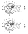
- 4a and 4b show a schematic cross section of a cylinder lock with a further embodiment of the control plate.
- Fig. 5 shows a detailed view of a possible embodiment of a control plate.
- 6 shows a detailed view of a further embodiment of a control plate.
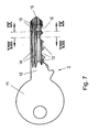
- Fig. 7 shows a side view of a flat key according to the invention.
- Fig. 8 shows a section through a flat key cut along the line VIII-VIII in Fig. 7.
- Fig. 9 shows a section through a flat key according to the invention cut along the line IX-IX of Fig. 7.
- the cylinder lock 1 shown in FIG. 1 consists of a housing 3 with a cylinder 4 rotatable therein.
- exemplary blocking elements here divided tumbler pins consisting of cylinder core pins 10 are housing pins 9 and springs 8 shown, which protrude through holes in the housing 3 and in the cylinder core 4 and are used for scanning cutting grooves 13 on the flat key 2.
- a slot 6 in the cylinder core in which the movable control plate 7 is arranged located between the innermost and the preceding tumbler pin a slot 6 in the cylinder core in which the movable control plate 7 is arranged.
- control extensions 19 of the control plate 7 slide while in the control profile grooves 15 and are guided by them. Upon further insertion of the key 2, the control extensions 19 slide over the oblique sections of the control profile grooves 15 and thus cause the control plate 7 is displaced against the force of the springs 17 in the cylinder core. So that the control plate can be guided correctly, it is necessary that at least one leading edge is always present in the entire area of the control profile grooves 15. This must be taken into account above all in the case of overlaps between the oblique sections of the control profile grooves 15 and the continuous longitudinal profile grooves 14.
- FIG. 2 and 3 each show a schematic cross section with a control plate 7 which on both sides of the key channel in this projecting control extensions 19, whereby control profile grooves 15 can be scanned on both key flat sides 23.
- Fig. 3 shows the rest position in which the control plate with a recess 18 in the housing 3 of the cylinder lock is engaged and blocks the cylinder core 4 against rotation.
- Fig. 2 shows the cylinder lock according to the invention in the release position in which after inserting the correct key, the control plate 7 has been moved into the cylinder core.
- FIG. 4a and 4b show another possible embodiment of a cylinder lock according to the invention in which a control plate 7 is provided which scans control profile grooves 15 only on a key flat side 23 by means of the control extensions 19.
- the spring 17 of the control plate 7 is counteracted on a ball 20 which is pressed in the corresponding core hole.
- a compressed bolt can also be provided.
- a Steuerrastelement 21 is provided which is in the rest position, as shown in Fig. 4a, with a latching recess 18 in the housing 3 is engaged.
- FIGS. 5 and 6 show detailed views of two possible embodiments of the control plate 7.
- FIG. 5 shows a control plate 7 with control extensions 19 on both sides of the key channel.
- Fig. 6 shows a control plate 7 according to a Ausf crawlrungsform as shown in Fig. 4.
- FIG. 7 to 9 each show views of a flat key 2 according to the invention with a key handle 11 and a key shank 12, incision grooves 13 continuous L Lucassprofilnuten 14 and of the key tip 16 in the direction key handle 11 extending Steuerprofilnuten 15.
- Fig. 7 shows a section of Control profile grooves 15 obliquely, at an angle deviating from 0 ° to the continuous L Lucassprofilnuten 14.
- the sectional view of the flat key shown in Fig. 8 of FIG. 7 shows the profile 25 in the region of the continuous L Lucassprofilnuten 14.
- the sectional view shown in Fig. 9 shows the Control profile 24 in the present area with continuous L Lucassprofilnuten 14 and the control profile grooves 15.
- the control profile 24 may be equal to or less than the profile 25 without control profile grooves.
Landscapes
- Physics & Mathematics (AREA)
- Electromagnetism (AREA)
- Lock And Its Accessories (AREA)
- Preventing Unauthorised Actuation Of Valves (AREA)
- Container, Conveyance, Adherence, Positioning, Of Wafer (AREA)
- Accommodation For Nursing Or Treatment Tables (AREA)
- Prostheses (AREA)
Applications Claiming Priority (2)
| Application Number | Priority Date | Filing Date | Title |
|---|---|---|---|
| AT0000406U AT9229U1 (de) | 2006-01-05 | 2006-01-05 | Zylinderschloss und flachschlüssel |
| AT172006A AT503051B1 (de) | 2006-01-05 | 2006-01-05 | Zylinderschloss und flachschlüssel |
Publications (2)
| Publication Number | Publication Date |
|---|---|
| EP1806467A2 true EP1806467A2 (fr) | 2007-07-11 |
| EP1806467A3 EP1806467A3 (fr) | 2008-11-26 |
Family
ID=36591086
Family Applications (1)
| Application Number | Title | Priority Date | Filing Date |
|---|---|---|---|
| EP07000152A Withdrawn EP1806467A3 (fr) | 2006-01-05 | 2007-01-05 | Serrure à cylindre et clé plate |
Country Status (7)
| Country | Link |
|---|---|
| EP (1) | EP1806467A3 (fr) |
| AU (1) | AU2007200044A1 (fr) |
| DE (1) | DE202006003869U1 (fr) |
| FR (1) | FR2895764B3 (fr) |
| GB (1) | GB2433959A (fr) |
| IE (1) | IES20060235A2 (fr) |
| NL (1) | NL2000046C1 (fr) |
Families Citing this family (5)
| Publication number | Priority date | Publication date | Assignee | Title |
|---|---|---|---|---|
| CN104261134A (zh) * | 2007-05-31 | 2015-01-07 | 北京银融科技有限责任公司 | 一种传输器的方法及装置 |
| CN101314438B (zh) * | 2007-05-31 | 2015-09-09 | 北京银融科技有限责任公司 | 一种带有约束绳的传输器及其方法 |
| CN101638954B (zh) * | 2008-07-30 | 2013-01-09 | 吴潮胜 | 一种防盗锁具 |
| FR2962752B1 (fr) * | 2010-07-13 | 2012-08-17 | Assa Abloy Aube Anjou | Cylindre de serrure pour cle plate |
| CN104343288B (zh) * | 2013-07-25 | 2017-11-14 | 谭章梅 | 钥匙、锁芯及相应的锁具 |
Family Cites Families (9)
| Publication number | Priority date | Publication date | Assignee | Title |
|---|---|---|---|---|
| US3035433A (en) * | 1959-10-30 | 1962-05-22 | Eagle Lock Corp | Lock mechanism |
| AT371880B (de) * | 1980-09-25 | 1983-08-10 | Evva Werke | Flachschluessel |
| DE3603687A1 (de) * | 1986-02-06 | 1987-08-13 | Dom Sicherheitstechnik | Aus schliesszylinder und zugehoerigem flachschluessel bestehende schliesseinrichtung |
| AT392508B (de) * | 1987-07-03 | 1991-04-25 | Evva Werke | Flachschluessel und zugehoeriges zylinderschloss |
| DE29708308U1 (de) * | 1996-12-23 | 1997-08-28 | C. Ed. Schulte GmbH Zylinderschloßfabrik, 42551 Velbert | Schließzylinder |
| FR2758847B1 (fr) * | 1997-01-28 | 1999-05-28 | Ymos France | Barillet de serrure a paillettes et goupilles |
| FR2763624B1 (fr) * | 1997-05-22 | 1999-06-25 | Valeo Securite Habitacle | Verrou de vehicule automobile comportant une barrette perfectionnee de retenue des paillettes |
| ATE204053T1 (de) * | 1998-04-04 | 2001-08-15 | Schlosssicherungen Gera Gmbh | Schliesszylinder mit zugeordnetem flachschlüssel im variablen stufenprofil |
| DE10313125A1 (de) * | 2003-03-24 | 2004-10-14 | Huf Hülsbeck & Fürst Gmbh & Co. Kg | Schließzylinder |
-
2006
- 2006-03-11 DE DE202006003869U patent/DE202006003869U1/de not_active Expired - Lifetime
- 2006-03-24 FR FR0602573A patent/FR2895764B3/fr not_active Expired - Fee Related
- 2006-03-27 IE IE20060235A patent/IES20060235A2/en not_active IP Right Cessation
- 2006-03-29 GB GB0606213A patent/GB2433959A/en not_active Withdrawn
- 2006-04-03 NL NL2000046A patent/NL2000046C1/nl not_active IP Right Cessation
-
2007
- 2007-01-05 AU AU2007200044A patent/AU2007200044A1/en not_active Abandoned
- 2007-01-05 EP EP07000152A patent/EP1806467A3/fr not_active Withdrawn
Also Published As
| Publication number | Publication date |
|---|---|
| EP1806467A3 (fr) | 2008-11-26 |
| GB2433959A (en) | 2007-07-11 |
| FR2895764A3 (fr) | 2007-07-06 |
| NL2000046C1 (nl) | 2006-07-05 |
| FR2895764B3 (fr) | 2007-11-09 |
| GB0606213D0 (en) | 2006-05-10 |
| DE202006003869U1 (de) | 2006-06-01 |
| AU2007200044A1 (en) | 2007-07-19 |
| IES20060235A2 (en) | 2006-10-18 |
Similar Documents
| Publication | Publication Date | Title |
|---|---|---|
| EP0335069B1 (fr) | Clef plate pour serrures cylindriques ainsi que sa serrure cylindrique | |
| EP2314807B1 (fr) | Système de verrouillage | |
| EP2310598B1 (fr) | Serrure a pompe comportant un boitier cylindrique et cle plate pour une serrure a pompe | |
| EP2454429B1 (fr) | Dispositif de fermeture | |
| DE19944070C2 (de) | Schließvorrichtung, insbesondere für Kraftfahrzeuge | |
| EP1816288B1 (fr) | Serrure cylindrique et clé plate | |
| EP1712714B1 (fr) | Combinaison d'une clé plate et d'une serrure cylindrique | |
| EP2536902A1 (fr) | Système de fermeture, clé et ébauche de clé | |
| EP2792822B1 (fr) | Codage via des poutres de blocage | |
| EP2360334A2 (fr) | Cylindre de fermeture | |
| EP1272720B1 (fr) | Serrure a pompe comportant un boitier cylindrique et cle plate destinee a une serrure a pompe | |
| DE202006003869U1 (de) | Zylinderschloss und Flachschlüssel | |
| DE102011000443B4 (de) | Schließzylinder insbesondere zur Betätigung eines Schaltschlosses | |
| EP1806466A2 (fr) | Serrure cylindrique avec un coulisseau et clé plate avec une nervure de guidage | |
| AT503051B1 (de) | Zylinderschloss und flachschlüssel | |
| AT9229U1 (de) | Zylinderschloss und flachschlüssel | |
| DD142075A5 (de) | Steuereinrichtung | |
| DE8534096U1 (de) | Zylinderschloß mit einer Nachschließsicherung | |
| EP1577469B1 (fr) | Clé | |
| EP2522796B1 (fr) | Clé destinée à fermer un cylindre de serrure | |
| AT503121B1 (de) | Zylinderschloss sowie flachschlüssel | |
| EP2952656B1 (fr) | Cylindre profilé doté d'un logement de cylindre | |
| AT527023A2 (de) | Schlüssel für ein Zylinderschloss und Zylinderschloss | |
| DE102008023984A1 (de) | Schließvorrichtung |
Legal Events
| Date | Code | Title | Description |
|---|---|---|---|
| PUAI | Public reference made under article 153(3) epc to a published international application that has entered the european phase |
Free format text: ORIGINAL CODE: 0009012 |
|
| AK | Designated contracting states |
Kind code of ref document: A2 Designated state(s): AT BE BG CH CY CZ DE DK EE ES FI FR GB GR HU IE IS IT LI LT LU LV MC NL PL PT RO SE SI SK TR |
|
| AX | Request for extension of the european patent |
Extension state: AL BA HR MK YU |
|
| PUAL | Search report despatched |
Free format text: ORIGINAL CODE: 0009013 |
|
| AK | Designated contracting states |
Kind code of ref document: A3 Designated state(s): AT BE BG CH CY CZ DE DK EE ES FI FR GB GR HU IE IS IT LI LT LU LV MC NL PL PT RO SE SI SK TR |
|
| AX | Request for extension of the european patent |
Extension state: AL BA HR MK RS |
|
| 17P | Request for examination filed |
Effective date: 20081110 |
|
| 17Q | First examination report despatched |
Effective date: 20090227 |
|
| AKX | Designation fees paid |
Designated state(s): AT BE BG CH CY CZ DE DK EE ES FI FR GB GR HU IE IS IT LI LT LU LV MC NL PL PT RO SE SI SK TR |
|
| AXX | Extension fees paid |
Extension state: RS Payment date: 20081110 Extension state: HR Payment date: 20081110 |
|
| STAA | Information on the status of an ep patent application or granted ep patent |
Free format text: STATUS: THE APPLICATION IS DEEMED TO BE WITHDRAWN |
|
| 18D | Application deemed to be withdrawn |
Effective date: 20100803 |