EP1806558A1 - Verfahren und Vorrichtung zur online Bestimmung der mikrometrischen Topographie von laufeneden Produkten - Google Patents
Verfahren und Vorrichtung zur online Bestimmung der mikrometrischen Topographie von laufeneden Produkten Download PDFInfo
- Publication number
- EP1806558A1 EP1806558A1 EP07008505A EP07008505A EP1806558A1 EP 1806558 A1 EP1806558 A1 EP 1806558A1 EP 07008505 A EP07008505 A EP 07008505A EP 07008505 A EP07008505 A EP 07008505A EP 1806558 A1 EP1806558 A1 EP 1806558A1
- Authority
- EP
- European Patent Office
- Prior art keywords
- line
- roughness
- optical axis
- image
- microscope
- Prior art date
- Legal status (The legal status is an assumption and is not a legal conclusion. Google has not performed a legal analysis and makes no representation as to the accuracy of the status listed.)
- Granted
Links
- 238000000034 method Methods 0.000 title claims abstract description 44
- 238000012876 topography Methods 0.000 title description 7
- 230000003287 optical effect Effects 0.000 claims abstract description 36
- 238000005286 illumination Methods 0.000 claims abstract description 27
- 239000011159 matrix material Substances 0.000 claims abstract description 8
- 238000005096 rolling process Methods 0.000 claims abstract description 6
- 238000011156 evaluation Methods 0.000 claims abstract description 5
- 229910000831 Steel Inorganic materials 0.000 claims description 11
- 239000010959 steel Substances 0.000 claims description 11
- 238000012545 processing Methods 0.000 claims description 9
- 230000003628 erosive effect Effects 0.000 claims description 6
- 230000005855 radiation Effects 0.000 claims description 6
- 238000003745 diagnosis Methods 0.000 claims description 5
- 239000002184 metal Substances 0.000 claims description 5
- 229910052751 metal Inorganic materials 0.000 claims description 5
- 239000013307 optical fiber Substances 0.000 claims description 5
- 238000010894 electron beam technology Methods 0.000 claims description 4
- 230000010339 dilation Effects 0.000 claims description 3
- 238000006073 displacement reaction Methods 0.000 claims description 3
- 230000000903 blocking effect Effects 0.000 claims description 2
- 238000004519 manufacturing process Methods 0.000 claims description 2
- 239000000047 product Substances 0.000 description 12
- 238000005259 measurement Methods 0.000 description 11
- 239000000758 substrate Substances 0.000 description 7
- 238000009826 distribution Methods 0.000 description 5
- 230000006978 adaptation Effects 0.000 description 3
- 238000004458 analytical method Methods 0.000 description 3
- 238000004364 calculation method Methods 0.000 description 3
- 229920000297 Rayon Polymers 0.000 description 2
- 239000000956 alloy Substances 0.000 description 2
- 229910045601 alloy Inorganic materials 0.000 description 2
- 238000009434 installation Methods 0.000 description 2
- 238000013507 mapping Methods 0.000 description 2
- 239000004033 plastic Substances 0.000 description 2
- 229920003023 plastic Polymers 0.000 description 2
- 239000002964 rayon Substances 0.000 description 2
- 101100322245 Caenorhabditis elegans des-2 gene Proteins 0.000 description 1
- 241000196324 Embryophyta Species 0.000 description 1
- 240000008042 Zea mays Species 0.000 description 1
- 229910052782 aluminium Inorganic materials 0.000 description 1
- XAGFODPZIPBFFR-UHFFFAOYSA-N aluminium Chemical compound [Al] XAGFODPZIPBFFR-UHFFFAOYSA-N 0.000 description 1
- 238000005097 cold rolling Methods 0.000 description 1
- 230000008878 coupling Effects 0.000 description 1
- 238000010168 coupling process Methods 0.000 description 1
- 238000005859 coupling reaction Methods 0.000 description 1
- 230000007547 defect Effects 0.000 description 1
- 230000001419 dependent effect Effects 0.000 description 1
- 238000011161 development Methods 0.000 description 1
- 238000010586 diagram Methods 0.000 description 1
- 238000009792 diffusion process Methods 0.000 description 1
- 230000009977 dual effect Effects 0.000 description 1
- 230000000694 effects Effects 0.000 description 1
- 229940082150 encore Drugs 0.000 description 1
- 238000005098 hot rolling Methods 0.000 description 1
- 238000005305 interferometry Methods 0.000 description 1
- 239000000314 lubricant Substances 0.000 description 1
- 238000005461 lubrication Methods 0.000 description 1
- 239000007769 metal material Substances 0.000 description 1
- 150000002739 metals Chemical class 0.000 description 1
- 239000003973 paint Substances 0.000 description 1
- 238000010422 painting Methods 0.000 description 1
- 230000000135 prohibitive effect Effects 0.000 description 1
- 230000035945 sensitivity Effects 0.000 description 1
- 230000003068 static effect Effects 0.000 description 1
- 239000013589 supplement Substances 0.000 description 1
- 238000013519 translation Methods 0.000 description 1
Images



Classifications
-
- G—PHYSICS
- G01—MEASURING; TESTING
- G01B—MEASURING LENGTH, THICKNESS OR SIMILAR LINEAR DIMENSIONS; MEASURING ANGLES; MEASURING AREAS; MEASURING IRREGULARITIES OF SURFACES OR CONTOURS
- G01B11/00—Measuring arrangements characterised by the use of optical techniques
- G01B11/30—Measuring arrangements characterised by the use of optical techniques for measuring roughness or irregularity of surfaces
- G01B11/303—Measuring arrangements characterised by the use of optical techniques for measuring roughness or irregularity of surfaces using photoelectric detection means
Definitions
- the present invention relates to a development of the process described in the unpublished patent application No. BE2002 / 0192 (Method and apparatus for in-line roughness determination of moving steel belts), extended to any metallic product having a flat surface, including cold-rolled or hot-rolled products and also rolling rolls, whether when printing or using them online.
- the present invention makes it possible to reconstruct the topography of the observed surface and more particularly to calculate all the 2D and 3D roughness parameters.
- the invention also relates to the device for implementing the method.
- the strip has a roughness as constant as possible over its entire surface. It is also preferable that strips intended for the same application, for example bodywork elements, all have a comparable roughness.
- steel sheets obtained by cold rolling will advantageously be replaced in the future by thin sheets obtained by hot rolling. This trend is dictated by economic reasons.
- the roughness of the sheet is very important, it is directly related to the amount of lubricant that can accumulate on the surface of the product during lubrication in the critical areas of the formed part.
- the roughness value Ra is expressed in terms of the arithmetic mean of a filtered roughness profile determined from the deviations of a measurement curve from a mean line. It can in particular be calculated according to DIN 3768, without this definition being limiting in the context of the present invention. Other roughness parameters, such as the peak value, the number of peaks, the shape and the repeatability of the craters, in the case of deterministic roughness, could also be used.
- the state of the art includes two types of profilers for determining roughness: tactile and optical profilers.
- the tactile methods use reading tips brought into contact with the surface.
- the interferometric methods use the interference resulting from the superposition of incident light waves on a surface and light waves reflected by this same surface. Their accuracy can be very large, of the order of a nanometer and they provide a 3D profile of the observed surface, a profile that can be used to calculate the various 2D and 3D roughness parameters.
- these methods require a perfectly static surface, that is to say without vibration and without movement, for the duration of the measurement, typically for one to several seconds. This is therefore prohibitive for an online application on a scrolling product.
- the profile of the surface is measured by a series of successive positions of a point of the studied surface at its highest level of focus. This requires a vertical scan for each observation point of the surface. The accuracy reached can be very high but the vertical scanning step requires a measurement time incompatible with a scrolling product, several seconds.
- Another method used is that of measuring the direction of reflection of a ray incident to the surface. Starting from an incident ray forming a certain angle with the normal to this surface, the reflection direction is measured through an optical assembly making it possible to increase the sensitivity of the measurement.
- the industrial experience of this type of measurement as well as the calculations obtained show that the accuracy is limited by the types of slopes encountered on the surfaces observed.
- the measurement interval in Ra typically from 0.3 ⁇ m to 3 ⁇ m, is not effectively covered.
- the method of measuring the reflection lobe (diffusion) of a ray incident on the surface is also used.
- Beckmann et al. P. Beckman, A. Spizzichino, The scattering of electromagnetic waves from rough surfaces, Pergamon Press, 1963
- a relation exists between the arithmetic roughness of this surface and the power reflected by this same surface see patent applications LU-A-87,483 , LU-A-87 630 , EP-A-484,310 and BE-A-905 862 ).
- This method is effective in measuring the arithmetic roughness in line but provides no other information about the topography of the surface, that is to say for example the distribution of trays (or “peaks”) and hollows (or “valleys”) in the case of so-called random roughness, and the shape and distribution of craters in the case of deterministic roughness.
- a camera records this multiple line shadow pattern and the recorded pattern is superimposed on a plurality of parallel and equidistant scan lines oriented perpendicularly. with shadow lines. The distances between the points where the adjacent shadow lines intersect the respective scan lines are measured to determine the roughness or other surface size.
- the document US Patent 4,650,333 discloses a non-contact system for detecting defects on the tracks of a printed circuit and for measuring the height of circuit components relative to the substrate.
- the system includes a light source for illuminating the substrate and circuit components as well as a scanner for instantaneously receiving energy reflected from the substrate and circuit components and generating a reflected energy response signal. said signal being adapted to vary with the intensity of the reflected energy.
- An analyzer is connected to the scanner for correlating the generated signal to a measurement representative of the height of the circuit components relative to the substrate. Variations and nonuniformity of the substrate surface due to folding, warping or any other cause can thus be taken into account in order to provide an accurate measurement of the height of a circuit component with respect to the surface of the substrate. substrate on which it is mounted.
- the present invention aims to provide a method for acquiring the image of a surface of given dimensions, preferably having at least 500 ⁇ m of field of view width, in a very short time, that is to say in less than 100 ns and thus freeze the movement of a product that can scroll even at high speed that is to say more than 10 m / s.
- Another object of the present invention is to be able to record the precise profile of the surface, or random topographic survey of the surface, by using a projection of one or more micrometric lines, for example 5 ⁇ m thick and at least equal to the width of the field of vision, of known positions, preferably parallel to each other and separated for example from 10 to 50 ⁇ m. These lines are projected at a certain angle, so as to be focused on the surface to be observed, the technique used is that of triangulation.
- a further object of the invention is to be able to reconstitute, in an inherent manner to the technique described, the general appearance of the surface and to give an indication of the distribution of the trays and troughs or of the distribution and shape. craters.
- a first object of the present invention relates to a method for the establishment of the global micrometric topographic survey and the on-line determination of 2D and 3D roughness parameters of a running surface, preferably a steel surface.
- the aforementioned micrometric line is projected at an angle of incidence of between 10 and 80 °, and preferably between 25 and 65 °, with respect to the aforementioned optical axis (Z) and we proceed to the acquisition of an image of a part of the surface of given dimensions.
- This image is then numerically processed so as to isolate a projection from the line, smooth it and then determine the edge lines and the center line.
- a local topographic survey of the surface is then made by a line between and including these edge lines, preferably by the middle line.
- the position of the micrometric lines projected relative to each other is known. These are preferably parallel to one another and preferably separated by a distance of between 10 and 50 ⁇ m, their width preferably being equal to 3 ⁇ m ⁇ 2 ⁇ m.
- a second essential characteristic of the invention is that the laser light source is also used to make a global lighting and in that the image obtained by the global lighting is treated to isolate 2D and 3D roughness characteristics, namely essentially the position of valleys and / or craters, in order to position in a global manner the local topographic survey. We will then speak of a global survey to characterize the result obtained.
- the combination of the two aforementioned essential characteristics then makes it possible to reconstitute a surface representative of the real surface by using a determined number of images and from there, makes it possible to calculate 3D roughness parameters.
- a local topographic survey will more precisely be defined as being the reading of a roughness parameter in a given direction, for example X, perpendicular to the Z axis (optical axis of the microscope).
- This is a sectional survey (the X, Y and Z reference axes are defined according to the usual conventional way).
- An overall topographic survey shall be defined as the reading of a roughness parameter along a surface (XY) perpendicular to the Z axis.
- an overall topographic survey may be obtained by scanning along the Y axis.
- a choice of at least two types of overall illumination is preferably made by passing the incident beam into a beam splitter (beamsplitter) inside the microscope or illuminating the surface from outside the microscope.
- a beam splitter beamsplitter
- the overall illumination is illumination illuminating said area under oblique incidence, between 5 and 40 °, and preferably 20 ° ⁇ 2 ° relative to the plane of the surface.
- the overall lighting is brightfield lighting.
- the observed image of the projected line on the surface has the appearance of a broken line for determining the local variations of height ( ⁇ Z) by triangulation.
- the concrete implementation of the invention is realized by the fact that the broken line measured as a function of the pixel position is converted by calibration into a micrometric height profile.
- the present invention will preferably apply to a surface belonging to a strip of steel running on a production line at a speed of between 1 and 20 m / s, to a surface having a roughness of essentially random type, such that a shot blasted surface or surface having a substantially deterministic type of roughness, such as a laser etched or electron beam textured rolling cylinder surface.
- the above device comprises a second assembly consisting of two elements, such as motorized rotation tables, for positioning the optical axis (Z) perpendicularly to the plane containing the observed surface.
- the second set can be provided with an antivibration system allowing to isolate said assembly of the metal frame as existing in industrial line and subjected to possible vibrations.
- the second assembly may also be coupled to a displacement device for protecting it during a line incident, preferably a motorized linear axis.
- said hardware and software means comprise a computer controlling the two aforementioned sets.
- the microscope may comprise a blocking filter for the radiation of the distance sensor and passing for surface illumination radiation and line projection.
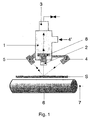
- FIG. 1 represents the functional diagram of the measuring device used to implement the method of the invention.
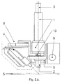
- Figure 2.a is a schematic plan view of the measuring device of Figure 1.
- Figure 2.b. is a schematic representation in elevation of the device of FIG.
- Figures 3.a and 3.b show digital images obtained with the measuring device described in Figure 1 in line projection with global illumination.
- Figures 3.c and 3.e show overall surface images.
- Figures 3.d and 3.f represent topographic surveys obtained from a line projection scan.
- Figures 4.a and 4.b show schematically the principle of triangulation used.
- Figure 5 shows the curve connecting the computed 2D arithmetic roughness to the mechanically measured roughness for a series of samples.
- the present invention relates to a method for topographic surveying and on-line evaluation of 2D and 3D roughness parameters of a running surface, preferably a steel surface.
- This reconstruction of topographic profile will use as supplement the oblique illumination previously described in the application N ° BE2002 / 0192 in the case for example of so-called random roughness, or "brightfield” lighting in the case for example of so-called deterministic roughness.
- an online microscope developed by the applicant (GaScope ®) and described in FIG 1 to acquire images of the surface.
- This microscope can use either an oblique illumination 4, for example at an inclination of between 5 and 40 °, and preferably at 20 °, or a "brightfield" illumination 4 '.
- the on-line measuring apparatus A described in FIGS. 1 and 2 for carrying out the method of the invention comprises at least one industrial microscope 1 equipped with a long working distance objective 2, preferably greater than 5 mm, a camera adaptation lens, a camera with an analog or digital output, for example a matrix camera 3, preferably CCD or C-MOS, a lighting comprising a laser used for oblique illumination 4 or "brightfield" 4 'as already mentioned, a micrometric line projection device (s) 8, a distance sensor 5 and a motor 9 acting on the displacement along the Z axis which is the optical axis of the microscope to allow the correct focusing of the system.
- a micrometric line projection device (s) 8 a distance sensor 5 and a motor 9 acting on the displacement along the Z axis which is the optical axis of the microscope to allow the correct focusing of the system.
- the microscope may advantageously be equipped with a filter 10 which will block the radiation of the distance sensor and pass for the illumination radiation of the surface and the projection of lines.
- FIG. 1 represents the case of a running steel strip, such that the band S is positioned by applying it to the surface of a cylinder 6 by traction and positioning the microscope in such a way that The optical axis of the system orthogonally crosses the axis 7 of the cylinder 6 and is included in an arc segment located between the first and the last line of contact between the web supporting the surface and the cylinder.
- the apparatus A is mounted on a set D comprising two elements B and C, such as motorized rotation tables, said set D making it possible to position the optical axis Z perpendicular to the plane containing the observed surface S (FIGS. 2).
- the assembly D is provided with an antivibration system for isolating said assembly of the metal frame as existing in the industrial line and subjected to the various vibrations often present in this type of industrial environment.
- the assembly can be placed advantageously on a positioning / parking system, for example a linear motorized axis, to protect the system during a line incident.
- the method of the invention uses a laser light source 4,4 'passing through one or more optical fibers and an optical system which, associated with a precise positioning assembly, for example two translation tables constitute the micrometric projection device 8.
- This device produces one or more micrometric lines having for example 3 ⁇ 2 ⁇ m in width and whose length is at least equal to the width of the field of view. These lines are projected at an angle of incidence of 45 ⁇ 20 ° with respect to the surface.
- the laser light source can advantageously be used in parallel for oblique illumination (see patent application BE2002 / 0192 ) in the case of so-called random roughness or as "brightfield” lighting (see patent application BE2001 / 0398 ) in the case of deterministic roughness.
- This dual use of the same source is achieved by means of a beamsplitter separating the incident energy into two, one transmitted and the other reflected.
- a combination of the two above-mentioned essential characteristics would then consist, for example in the case of deterministic roughness, in associating with each treated line a position in an arbitrarily chosen initial image.
- the width of the crater or craters at the location crossed by the line, as well as the distance between the centers of the hollows thus determined, making it possible to achieve this positioning.
- FIG. 4.a illustrates the principle of the triangulation measurement making it possible to determine the height variation ⁇ Z under oblique illumination of angle ⁇ with respect to the normal Z to the moving metal strip.
- This normal Z gives the observation direction of the camera 3, that is to say the optical axis of the system.
- Figure 4.b. represents the different levels of possible impacts X1, X2, X3 of a projected point on a surface respectively at a height Z1, Z2, Z3.
- FIG. 5 represents an example of a curve making it possible to relate the results obtained by the calculation above for the 2D roughness with the corresponding values measured mechanically in the case of a series of samples.
- Figures 3.a and 3.b are images obtained by line projection and with global lighting ("brightfield").
- Figures 3.c and 3.e are global surface images.
- Figures 3.d and 3.f are the corresponding 3D topographic surveys shown in a perspective view. These records correspond respectively to a standard case and a case of roughness. These topographic surveys are obtained by moving the observed sample by a known step, by analyzing each image thus obtained and by reconstructing an XYZ mapping of the surface.
Landscapes
- Physics & Mathematics (AREA)
- General Physics & Mathematics (AREA)
- Length Measuring Devices By Optical Means (AREA)
- Length Measuring Devices With Unspecified Measuring Means (AREA)
Applications Claiming Priority (2)
| Application Number | Priority Date | Filing Date | Title |
|---|---|---|---|
| BE2002/0688A BE1015227A3 (fr) | 2002-11-29 | 2002-11-29 | Procede et dispositif pour la determination en ligne de la topographie micrometrique de produits en mouvement. |
| EP03447229A EP1429114A3 (de) | 2002-11-29 | 2003-09-18 | Verfahren und Vorrichtung zur online Bestimmung der mikrometrischen Topographie von laufeneden Produkten |
Related Parent Applications (2)
| Application Number | Title | Priority Date | Filing Date |
|---|---|---|---|
| EP03447229.0 Division | 2003-09-18 | ||
| EP03447229A Division EP1429114A3 (de) | 2002-11-29 | 2003-09-18 | Verfahren und Vorrichtung zur online Bestimmung der mikrometrischen Topographie von laufeneden Produkten |
Publications (2)
| Publication Number | Publication Date |
|---|---|
| EP1806558A1 true EP1806558A1 (de) | 2007-07-11 |
| EP1806558B1 EP1806558B1 (de) | 2012-10-31 |
Family
ID=32315128
Family Applications (2)
| Application Number | Title | Priority Date | Filing Date |
|---|---|---|---|
| EP03447229A Ceased EP1429114A3 (de) | 2002-11-29 | 2003-09-18 | Verfahren und Vorrichtung zur online Bestimmung der mikrometrischen Topographie von laufeneden Produkten |
| EP07008505A Expired - Lifetime EP1806558B1 (de) | 2002-11-29 | 2003-09-18 | Verfahren und Vorrichtung zur online Bestimmung der mikrometrischen Topographie von laufenden Produkten |
Family Applications Before (1)
| Application Number | Title | Priority Date | Filing Date |
|---|---|---|---|
| EP03447229A Ceased EP1429114A3 (de) | 2002-11-29 | 2003-09-18 | Verfahren und Vorrichtung zur online Bestimmung der mikrometrischen Topographie von laufeneden Produkten |
Country Status (3)
| Country | Link |
|---|---|
| EP (2) | EP1429114A3 (de) |
| BE (1) | BE1015227A3 (de) |
| ES (1) | ES2398665T3 (de) |
Cited By (1)
| Publication number | Priority date | Publication date | Assignee | Title |
|---|---|---|---|---|
| EP2517799A1 (de) | 2011-04-26 | 2012-10-31 | Centre de Recherches Métallurgiques asbl - Centrum voor Research in de Metallurgie vzw | Vorrichtung und Verfahren für die industrielle online Mikrotopografie und Welligkeitsmessungen bewegender Produkte |
Families Citing this family (5)
| Publication number | Priority date | Publication date | Assignee | Title |
|---|---|---|---|---|
| FR2873205B1 (fr) * | 2004-07-19 | 2007-05-18 | Plastic Omnium Cie | Procede et poste de controle de peinture de piece de carrosserie de vehicules automobiles |
| FR2873204B1 (fr) * | 2004-07-19 | 2007-04-27 | Plastic Omnium Cie | Appareil de mesure pour le controle de pieces de carrosserie peintes, muni d'un dispositif anti-deterioration |
| US7289216B2 (en) * | 2004-07-19 | 2007-10-30 | Compagnie Plastic Omnium | Station for inspecting the painting of motor vehicle parts |
| RU2680608C1 (ru) * | 2017-11-23 | 2019-02-25 | Федеральное государственное бюджетное образовательное учреждение высшего образования "Чувашская государственная сельскохозяйственная академия" | Способ профилирования дневной поверхности почвы на элементарной площадке в полевых условиях |
| CN110702008B (zh) * | 2019-11-11 | 2025-06-24 | 深圳市泰斯特尔系统科技有限公司 | 一种机器视觉和扫描检测装置及其工作方法 |
Citations (10)
| Publication number | Priority date | Publication date | Assignee | Title |
|---|---|---|---|---|
| US3843227A (en) * | 1969-02-08 | 1974-10-22 | Nippon Kogaku Kk | Light dissecting optical system |
| US3908079A (en) * | 1974-02-15 | 1975-09-23 | Gen Electric | Surface roughness measurement instrument |
| US4650333A (en) | 1984-04-12 | 1987-03-17 | International Business Machines Corporation | System for measuring and detecting printed circuit wiring defects |
| BE905862A (fr) | 1985-12-05 | 1987-06-03 | Centre Rech Metallurgique | Procede de mesure en continu de la rugosite de la surface d'un produit lamine a froid. |
| LU87483A1 (fr) | 1988-03-25 | 1989-08-30 | Centre Rech Metallurgique | Procede de reglage de la rugosite d'un produit plat lamine |
| LU87630A1 (fr) | 1988-12-05 | 1990-03-13 | Centre Rech Metallurgique | Dispositif de mesure de la rugosite de la surface d'un produit metallique |
| EP0484310A2 (de) | 1990-10-29 | 1992-05-06 | CENTRE DE RECHERCHES METALLURGIQUES CENTRUM VOOR RESEARCH IN DE METALLURGIE Association sans but lucratif | Vorrichtung zum Messen der Rauhigkeit eines sich bewegenden Metallerzeugnisses |
| US5266791A (en) * | 1991-10-17 | 1993-11-30 | Fuji Photo Optical Co., Ltd. | Autofocus binocular stereomicroscope |
| US5311286A (en) | 1992-04-01 | 1994-05-10 | Materials Technologies Corporation | Apparatus and method for optically measuring a surface |
| US20040233421A1 (en) | 2001-05-08 | 2004-11-25 | Wolfgang Weinhold | Method and device for examining an object in a contactless manner, especially for examining the surface form of the same |
-
2002
- 2002-11-29 BE BE2002/0688A patent/BE1015227A3/fr not_active IP Right Cessation
-
2003
- 2003-09-18 EP EP03447229A patent/EP1429114A3/de not_active Ceased
- 2003-09-18 ES ES07008505T patent/ES2398665T3/es not_active Expired - Lifetime
- 2003-09-18 EP EP07008505A patent/EP1806558B1/de not_active Expired - Lifetime
Patent Citations (10)
| Publication number | Priority date | Publication date | Assignee | Title |
|---|---|---|---|---|
| US3843227A (en) * | 1969-02-08 | 1974-10-22 | Nippon Kogaku Kk | Light dissecting optical system |
| US3908079A (en) * | 1974-02-15 | 1975-09-23 | Gen Electric | Surface roughness measurement instrument |
| US4650333A (en) | 1984-04-12 | 1987-03-17 | International Business Machines Corporation | System for measuring and detecting printed circuit wiring defects |
| BE905862A (fr) | 1985-12-05 | 1987-06-03 | Centre Rech Metallurgique | Procede de mesure en continu de la rugosite de la surface d'un produit lamine a froid. |
| LU87483A1 (fr) | 1988-03-25 | 1989-08-30 | Centre Rech Metallurgique | Procede de reglage de la rugosite d'un produit plat lamine |
| LU87630A1 (fr) | 1988-12-05 | 1990-03-13 | Centre Rech Metallurgique | Dispositif de mesure de la rugosite de la surface d'un produit metallique |
| EP0484310A2 (de) | 1990-10-29 | 1992-05-06 | CENTRE DE RECHERCHES METALLURGIQUES CENTRUM VOOR RESEARCH IN DE METALLURGIE Association sans but lucratif | Vorrichtung zum Messen der Rauhigkeit eines sich bewegenden Metallerzeugnisses |
| US5266791A (en) * | 1991-10-17 | 1993-11-30 | Fuji Photo Optical Co., Ltd. | Autofocus binocular stereomicroscope |
| US5311286A (en) | 1992-04-01 | 1994-05-10 | Materials Technologies Corporation | Apparatus and method for optically measuring a surface |
| US20040233421A1 (en) | 2001-05-08 | 2004-11-25 | Wolfgang Weinhold | Method and device for examining an object in a contactless manner, especially for examining the surface form of the same |
Non-Patent Citations (1)
| Title |
|---|
| P. BECKMAN; A. SPIZZICHINO: "The scattering of electromagnetic waves from rough surfaces", 1963, PERGAMON PRESS |
Cited By (1)
| Publication number | Priority date | Publication date | Assignee | Title |
|---|---|---|---|---|
| EP2517799A1 (de) | 2011-04-26 | 2012-10-31 | Centre de Recherches Métallurgiques asbl - Centrum voor Research in de Metallurgie vzw | Vorrichtung und Verfahren für die industrielle online Mikrotopografie und Welligkeitsmessungen bewegender Produkte |
Also Published As
| Publication number | Publication date |
|---|---|
| EP1429114A2 (de) | 2004-06-16 |
| BE1015227A3 (fr) | 2004-11-09 |
| ES2398665T3 (es) | 2013-03-20 |
| EP1429114A3 (de) | 2005-11-16 |
| EP1806558B1 (de) | 2012-10-31 |
Similar Documents
| Publication | Publication Date | Title |
|---|---|---|
| EP3218769B1 (de) | Analyseverfahren mit holographischer bestimmung einer position eines biologischen partikels | |
| EP1364181B9 (de) | Verfahren und einrichtung zur schnellen interferenziellen mikroskopischen abbildung eines objekts | |
| EP0985902B1 (de) | Interferometrische Vorrichtung zum Sichtbarmachung von Optischen Reflexion- und/oder Transmissionscharakteristiken im inneren eines Objektes | |
| EP2556164B1 (de) | Verfahren für den nachweis von clustern aus biologischen partikeln | |
| EP0732579B1 (de) | Verfahren zum Erkennen und Beurteilen von Fehlern in semi-reflektierender Oberflächenschicht | |
| BE1013663A6 (fr) | Appareil et procede pour examiner la forme de gemmes. | |
| EP3069185B1 (de) | Dreidimensionale fokussierungsvorrichtung und verfahren für ein mikroskop | |
| EP3394560A1 (de) | Vorrichtung und verfahren zur messung der höhe in gegenwart von dünnschichten | |
| EP1771714B1 (de) | Verfahren zur Prüfung einer optischen Komponente der ophthalmischen Industrie | |
| EP3394591B1 (de) | Beobachtungsverfahren einer probe in einer linsenlosen abbildung | |
| EP1580524A2 (de) | Verfahren und Vorrichtung zur Charakterisierung von Strukturschäden mittels Moiré- Schatten | |
| EP1084379A1 (de) | Verfahren und vorrichtung zur optoelektronischen formerfassung durch axiale beleuchtung | |
| EP1806558B1 (de) | Verfahren und Vorrichtung zur online Bestimmung der mikrometrischen Topographie von laufenden Produkten | |
| WO2014009519A1 (fr) | Procédé et système de reconstruction de propriétés optiques d'objets diffractants baignant dans un milieu liquide | |
| EP1157261B1 (de) | Verfahren und vorrichtung zur analyse einer hochdynamischen wellenfront | |
| WO2004017020A1 (fr) | Dispositif pour mesurer des variations dans le relief d'un objet | |
| EP1430271B1 (de) | Verfahren und einrichtung zur messung mindestens einer geometrischen grösse einer optisch reflektierenden oberfläche | |
| EP3724725A1 (de) | Verfahren zur kalibrierung einer analysevorrichtung und zugehörige vorrichtung | |
| FR3018603A1 (fr) | Dispositif d'analyse et d'imagerie d'une surface par deflectometrie et procede correspondant | |
| EP4483138B1 (de) | Systeme und verfahren zur analyse der oberflächenqualität eines substrats mit parallelen flächen | |
| EP3903098B1 (de) | Verfahren zur charakterisierung einer probe durch phasenbildgebung | |
| EP3114459B1 (de) | Verfahren und system zur charakterisierung eines adhäsionstatus von partikeln wie etwa zellen | |
| EP3080592A1 (de) | Verfahren und vorrichtung zur analyse der oberfläche eines substrats | |
| EP0053992A1 (de) | Verfahren und Einrichtung zur optischen Kontrolle der Oberflächenzustände von Metallgütern | |
| FR3146520A1 (fr) | Procédé et système de contrôle de pellicule d’huile sur tôle d’emboutissage pour véhicule automobile |
Legal Events
| Date | Code | Title | Description |
|---|---|---|---|
| PUAI | Public reference made under article 153(3) epc to a published international application that has entered the european phase |
Free format text: ORIGINAL CODE: 0009012 |
|
| AC | Divisional application: reference to earlier application |
Ref document number: 1429114 Country of ref document: EP Kind code of ref document: P |
|
| AK | Designated contracting states |
Kind code of ref document: A1 Designated state(s): AT BE BG CH CY CZ DE DK EE ES FI FR GB GR HU IE IT LI LU MC NL PT RO SE SI SK TR |
|
| 17P | Request for examination filed |
Effective date: 20071010 |
|
| 17Q | First examination report despatched |
Effective date: 20071105 |
|
| AKX | Designation fees paid |
Designated state(s): AT BE BG CH CY CZ DE DK EE ES FI FR GB GR HU IE IT LI LU MC NL PT RO SE SI SK TR |
|
| GRAP | Despatch of communication of intention to grant a patent |
Free format text: ORIGINAL CODE: EPIDOSNIGR1 |
|
| GRAJ | Information related to disapproval of communication of intention to grant by the applicant or resumption of examination proceedings by the epo deleted |
Free format text: ORIGINAL CODE: EPIDOSDIGR1 |
|
| GRAP | Despatch of communication of intention to grant a patent |
Free format text: ORIGINAL CODE: EPIDOSNIGR1 |
|
| GRAS | Grant fee paid |
Free format text: ORIGINAL CODE: EPIDOSNIGR3 |
|
| GRAP | Despatch of communication of intention to grant a patent |
Free format text: ORIGINAL CODE: EPIDOSNIGR1 |
|
| GRAA | (expected) grant |
Free format text: ORIGINAL CODE: 0009210 |
|
| AC | Divisional application: reference to earlier application |
Ref document number: 1429114 Country of ref document: EP Kind code of ref document: P |
|
| AK | Designated contracting states |
Kind code of ref document: B1 Designated state(s): AT BE BG CH CY CZ DE DK EE ES FI FR GB GR HU IE IT LI LU MC NL PT RO SE SI SK TR |
|
| REG | Reference to a national code |
Ref country code: CH Ref legal event code: EP Ref country code: GB Ref legal event code: FG4D Free format text: NOT ENGLISH |
|
| REG | Reference to a national code |
Ref country code: AT Ref legal event code: REF Ref document number: 582248 Country of ref document: AT Kind code of ref document: T Effective date: 20121115 |
|
| REG | Reference to a national code |
Ref country code: IE Ref legal event code: FG4D Free format text: LANGUAGE OF EP DOCUMENT: FRENCH |
|
| REG | Reference to a national code |
Ref country code: DE Ref legal event code: R096 Ref document number: 60342508 Country of ref document: DE Effective date: 20121227 |
|
| REG | Reference to a national code |
Ref country code: NL Ref legal event code: T3 |
|
| REG | Reference to a national code |
Ref country code: ES Ref legal event code: FG2A Ref document number: 2398665 Country of ref document: ES Kind code of ref document: T3 Effective date: 20130320 |
|
| PG25 | Lapsed in a contracting state [announced via postgrant information from national office to epo] |
Ref country code: FI Free format text: LAPSE BECAUSE OF FAILURE TO SUBMIT A TRANSLATION OF THE DESCRIPTION OR TO PAY THE FEE WITHIN THE PRESCRIBED TIME-LIMIT Effective date: 20121031 Ref country code: SE Free format text: LAPSE BECAUSE OF FAILURE TO SUBMIT A TRANSLATION OF THE DESCRIPTION OR TO PAY THE FEE WITHIN THE PRESCRIBED TIME-LIMIT Effective date: 20121031 |
|
| PG25 | Lapsed in a contracting state [announced via postgrant information from national office to epo] |
Ref country code: SI Free format text: LAPSE BECAUSE OF FAILURE TO SUBMIT A TRANSLATION OF THE DESCRIPTION OR TO PAY THE FEE WITHIN THE PRESCRIBED TIME-LIMIT Effective date: 20121031 Ref country code: CY Free format text: LAPSE BECAUSE OF FAILURE TO SUBMIT A TRANSLATION OF THE DESCRIPTION OR TO PAY THE FEE WITHIN THE PRESCRIBED TIME-LIMIT Effective date: 20121031 Ref country code: GR Free format text: LAPSE BECAUSE OF FAILURE TO SUBMIT A TRANSLATION OF THE DESCRIPTION OR TO PAY THE FEE WITHIN THE PRESCRIBED TIME-LIMIT Effective date: 20130201 Ref country code: PT Free format text: LAPSE BECAUSE OF FAILURE TO SUBMIT A TRANSLATION OF THE DESCRIPTION OR TO PAY THE FEE WITHIN THE PRESCRIBED TIME-LIMIT Effective date: 20130228 |
|
| PG25 | Lapsed in a contracting state [announced via postgrant information from national office to epo] |
Ref country code: BG Free format text: LAPSE BECAUSE OF FAILURE TO SUBMIT A TRANSLATION OF THE DESCRIPTION OR TO PAY THE FEE WITHIN THE PRESCRIBED TIME-LIMIT Effective date: 20130131 Ref country code: SK Free format text: LAPSE BECAUSE OF FAILURE TO SUBMIT A TRANSLATION OF THE DESCRIPTION OR TO PAY THE FEE WITHIN THE PRESCRIBED TIME-LIMIT Effective date: 20121031 Ref country code: EE Free format text: LAPSE BECAUSE OF FAILURE TO SUBMIT A TRANSLATION OF THE DESCRIPTION OR TO PAY THE FEE WITHIN THE PRESCRIBED TIME-LIMIT Effective date: 20121031 Ref country code: DK Free format text: LAPSE BECAUSE OF FAILURE TO SUBMIT A TRANSLATION OF THE DESCRIPTION OR TO PAY THE FEE WITHIN THE PRESCRIBED TIME-LIMIT Effective date: 20121031 Ref country code: CZ Free format text: LAPSE BECAUSE OF FAILURE TO SUBMIT A TRANSLATION OF THE DESCRIPTION OR TO PAY THE FEE WITHIN THE PRESCRIBED TIME-LIMIT Effective date: 20121031 |
|
| PG25 | Lapsed in a contracting state [announced via postgrant information from national office to epo] |
Ref country code: RO Free format text: LAPSE BECAUSE OF FAILURE TO SUBMIT A TRANSLATION OF THE DESCRIPTION OR TO PAY THE FEE WITHIN THE PRESCRIBED TIME-LIMIT Effective date: 20121031 |
|
| PLBE | No opposition filed within time limit |
Free format text: ORIGINAL CODE: 0009261 |
|
| STAA | Information on the status of an ep patent application or granted ep patent |
Free format text: STATUS: NO OPPOSITION FILED WITHIN TIME LIMIT |
|
| 26N | No opposition filed |
Effective date: 20130801 |
|
| REG | Reference to a national code |
Ref country code: DE Ref legal event code: R097 Ref document number: 60342508 Country of ref document: DE Effective date: 20130801 |
|
| PG25 | Lapsed in a contracting state [announced via postgrant information from national office to epo] |
Ref country code: MC Free format text: LAPSE BECAUSE OF FAILURE TO SUBMIT A TRANSLATION OF THE DESCRIPTION OR TO PAY THE FEE WITHIN THE PRESCRIBED TIME-LIMIT Effective date: 20121031 |
|
| REG | Reference to a national code |
Ref country code: CH Ref legal event code: PL |
|
| REG | Reference to a national code |
Ref country code: IE Ref legal event code: MM4A |
|
| PG25 | Lapsed in a contracting state [announced via postgrant information from national office to epo] |
Ref country code: CH Free format text: LAPSE BECAUSE OF NON-PAYMENT OF DUE FEES Effective date: 20130930 Ref country code: IE Free format text: LAPSE BECAUSE OF NON-PAYMENT OF DUE FEES Effective date: 20130918 Ref country code: LI Free format text: LAPSE BECAUSE OF NON-PAYMENT OF DUE FEES Effective date: 20130930 |
|
| PGFP | Annual fee paid to national office [announced via postgrant information from national office to epo] |
Ref country code: LU Payment date: 20140924 Year of fee payment: 12 |
|
| PGFP | Annual fee paid to national office [announced via postgrant information from national office to epo] |
Ref country code: GB Payment date: 20140924 Year of fee payment: 12 |
|
| PGFP | Annual fee paid to national office [announced via postgrant information from national office to epo] |
Ref country code: FR Payment date: 20140922 Year of fee payment: 12 |
|
| PGFP | Annual fee paid to national office [announced via postgrant information from national office to epo] |
Ref country code: NL Payment date: 20140922 Year of fee payment: 12 |
|
| PG25 | Lapsed in a contracting state [announced via postgrant information from national office to epo] |
Ref country code: TR Free format text: LAPSE BECAUSE OF FAILURE TO SUBMIT A TRANSLATION OF THE DESCRIPTION OR TO PAY THE FEE WITHIN THE PRESCRIBED TIME-LIMIT Effective date: 20121031 |
|
| PG25 | Lapsed in a contracting state [announced via postgrant information from national office to epo] |
Ref country code: HU Free format text: LAPSE BECAUSE OF FAILURE TO SUBMIT A TRANSLATION OF THE DESCRIPTION OR TO PAY THE FEE WITHIN THE PRESCRIBED TIME-LIMIT; INVALID AB INITIO Effective date: 20030918 |
|
| PG25 | Lapsed in a contracting state [announced via postgrant information from national office to epo] |
Ref country code: LU Free format text: LAPSE BECAUSE OF NON-PAYMENT OF DUE FEES Effective date: 20150918 |
|
| GBPC | Gb: european patent ceased through non-payment of renewal fee |
Effective date: 20150918 |
|
| REG | Reference to a national code |
Ref country code: NL Ref legal event code: MM Effective date: 20151001 |
|
| REG | Reference to a national code |
Ref country code: FR Ref legal event code: ST Effective date: 20160531 |
|
| PG25 | Lapsed in a contracting state [announced via postgrant information from national office to epo] |
Ref country code: GB Free format text: LAPSE BECAUSE OF NON-PAYMENT OF DUE FEES Effective date: 20150918 |
|
| PG25 | Lapsed in a contracting state [announced via postgrant information from national office to epo] |
Ref country code: FR Free format text: LAPSE BECAUSE OF NON-PAYMENT OF DUE FEES Effective date: 20150930 Ref country code: NL Free format text: LAPSE BECAUSE OF NON-PAYMENT OF DUE FEES Effective date: 20151001 |
|
| PGFP | Annual fee paid to national office [announced via postgrant information from national office to epo] |
Ref country code: IT Payment date: 20220825 Year of fee payment: 20 Ref country code: DE Payment date: 20220818 Year of fee payment: 20 Ref country code: AT Payment date: 20220819 Year of fee payment: 20 |
|
| PGFP | Annual fee paid to national office [announced via postgrant information from national office to epo] |
Ref country code: BE Payment date: 20220822 Year of fee payment: 20 |
|
| PGFP | Annual fee paid to national office [announced via postgrant information from national office to epo] |
Ref country code: ES Payment date: 20221003 Year of fee payment: 20 |
|
| P01 | Opt-out of the competence of the unified patent court (upc) registered |
Effective date: 20230413 |
|
| REG | Reference to a national code |
Ref country code: DE Ref legal event code: R071 Ref document number: 60342508 Country of ref document: DE |
|
| REG | Reference to a national code |
Ref country code: ES Ref legal event code: FD2A Effective date: 20230926 |
|
| REG | Reference to a national code |
Ref country code: BE Ref legal event code: MK Effective date: 20230918 |
|
| PG25 | Lapsed in a contracting state [announced via postgrant information from national office to epo] |
Ref country code: ES Free format text: LAPSE BECAUSE OF EXPIRATION OF PROTECTION Effective date: 20230919 |
|
| REG | Reference to a national code |
Ref country code: AT Ref legal event code: MK07 Ref document number: 582248 Country of ref document: AT Kind code of ref document: T Effective date: 20230918 |