EP1807708B1 - Capteur de courant de batterie pour véhicule automobile - Google Patents
Capteur de courant de batterie pour véhicule automobile Download PDFInfo
- Publication number
- EP1807708B1 EP1807708B1 EP05800153A EP05800153A EP1807708B1 EP 1807708 B1 EP1807708 B1 EP 1807708B1 EP 05800153 A EP05800153 A EP 05800153A EP 05800153 A EP05800153 A EP 05800153A EP 1807708 B1 EP1807708 B1 EP 1807708B1
- Authority
- EP
- European Patent Office
- Prior art keywords
- battery current
- current sensor
- measuring
- fact
- sensor
- Prior art date
- Legal status (The legal status is an assumption and is not a legal conclusion. Google has not performed a legal analysis and makes no representation as to the accuracy of the status listed.)
- Expired - Lifetime
Links
Images

Classifications
-
- H—ELECTRICITY
- H01—ELECTRIC ELEMENTS
- H01R—ELECTRICALLY-CONDUCTIVE CONNECTIONS; STRUCTURAL ASSOCIATIONS OF A PLURALITY OF MUTUALLY-INSULATED ELECTRICAL CONNECTING ELEMENTS; COUPLING DEVICES; CURRENT COLLECTORS
- H01R12/00—Structural associations of a plurality of mutually-insulated electrical connecting elements, specially adapted for printed circuits, e.g. printed circuit boards [PCB], flat or ribbon cables, or like generally planar structures, e.g. terminal strips, terminal blocks; Coupling devices specially adapted for printed circuits, flat or ribbon cables, or like generally planar structures; Terminals specially adapted for contact with, or insertion into, printed circuits, flat or ribbon cables, or like generally planar structures
- H01R12/50—Fixed connections
- H01R12/51—Fixed connections for rigid printed circuits or like structures
- H01R12/55—Fixed connections for rigid printed circuits or like structures characterised by the terminals
- H01R12/58—Fixed connections for rigid printed circuits or like structures characterised by the terminals terminals for insertion into holes
- H01R12/585—Terminals having a press fit or a compliant portion and a shank passing through a hole in the printed circuit board
-
- G—PHYSICS
- G01—MEASURING; TESTING
- G01R—MEASURING ELECTRIC VARIABLES; MEASURING MAGNETIC VARIABLES
- G01R1/00—Details of instruments or arrangements of the types included in groups G01R5/00 - G01R13/00 and G01R31/00
- G01R1/20—Modifications of basic electric elements for use in electric measuring instruments; Structural combinations of such elements with such instruments
- G01R1/203—Resistors used for electric measuring, e.g. decade resistors standards, resistors for comparators, series resistors, shunts
-
- G—PHYSICS
- G01—MEASURING; TESTING
- G01R—MEASURING ELECTRIC VARIABLES; MEASURING MAGNETIC VARIABLES
- G01R19/00—Arrangements for measuring currents or voltages or for indicating presence or sign thereof
- G01R19/0092—Measuring current only
-
- H—ELECTRICITY
- H01—ELECTRIC ELEMENTS
- H01R—ELECTRICALLY-CONDUCTIVE CONNECTIONS; STRUCTURAL ASSOCIATIONS OF A PLURALITY OF MUTUALLY-INSULATED ELECTRICAL CONNECTING ELEMENTS; COUPLING DEVICES; CURRENT COLLECTORS
- H01R11/00—Individual connecting elements providing two or more spaced connecting locations for conductive members which are, or may be, thereby interconnected, e.g. end pieces for wires or cables supported by the wire or cable and having means for facilitating electrical connection to some other wire, terminal, or conductive member, blocks of binding posts
- H01R11/11—End pieces or tapping pieces for wires, supported by the wire and for facilitating electrical connection to some other wire, terminal or conductive member
- H01R11/28—End pieces consisting of a ferrule or sleeve
- H01R11/281—End pieces consisting of a ferrule or sleeve for connections to batteries
- H01R11/287—Intermediate parts between battery post and cable end piece
-
- G—PHYSICS
- G01—MEASURING; TESTING
- G01R—MEASURING ELECTRIC VARIABLES; MEASURING MAGNETIC VARIABLES
- G01R31/00—Arrangements for testing electric properties; Arrangements for locating electric faults; Arrangements for electrical testing characterised by what is being tested not provided for elsewhere
- G01R31/36—Arrangements for testing, measuring or monitoring the electrical condition of accumulators or electric batteries, e.g. capacity or state of charge [SoC]
- G01R31/364—Battery terminal connectors with integrated measuring arrangements
-
- G—PHYSICS
- G01—MEASURING; TESTING
- G01R—MEASURING ELECTRIC VARIABLES; MEASURING MAGNETIC VARIABLES
- G01R31/00—Arrangements for testing electric properties; Arrangements for locating electric faults; Arrangements for electrical testing characterised by what is being tested not provided for elsewhere
- G01R31/36—Arrangements for testing, measuring or monitoring the electrical condition of accumulators or electric batteries, e.g. capacity or state of charge [SoC]
- G01R31/382—Arrangements for monitoring battery or accumulator variables, e.g. SoC
-
- H—ELECTRICITY
- H01—ELECTRIC ELEMENTS
- H01H—ELECTRIC SWITCHES; RELAYS; SELECTORS; EMERGENCY PROTECTIVE DEVICES
- H01H1/00—Contacts
- H01H1/58—Electric connections to or between contacts; Terminals
- H01H2001/5877—Electric connections to or between contacts; Terminals with provisions for direct mounting on a battery pole
-
- H—ELECTRICITY
- H01—ELECTRIC ELEMENTS
- H01R—ELECTRICALLY-CONDUCTIVE CONNECTIONS; STRUCTURAL ASSOCIATIONS OF A PLURALITY OF MUTUALLY-INSULATED ELECTRICAL CONNECTING ELEMENTS; COUPLING DEVICES; CURRENT COLLECTORS
- H01R13/00—Details of coupling devices of the kinds covered by groups H01R12/70 or H01R24/00 - H01R33/00
- H01R13/66—Structural association with built-in electrical component
- H01R13/665—Structural association with built-in electrical component with built-in electronic circuit
- H01R13/6683—Structural association with built-in electrical component with built-in electronic circuit with built-in sensor
Definitions
- the present invention relates to a battery current sensor for a motor vehicle, with a measuring sensor inserted into the battery circuit and with a measuring sensor connected to the measuring circuit, in which at least parts of the measuring circuit are arranged on a circuit carrier which is fixedly connected electrically and mechanically connected to the measuring sensor via connecting means ,
- a battery current sensor which is mechanically arranged directly on a pole terminal of the battery, is from the DE 199 61 311 A1 known.
- the measuring sensor is designed as a measuring resistor and connected via solder connections to a printed circuit board.
- the contact surfaces of the measuring sensor are made of copper, while the actual measuring resistor consists of manganin;
- the measuring sensor thus formed should thereby have the same temperature expansion coefficient as the board material used.
- a battery current sensor according to the preamble is known from DE 203 18 266 U1 known.
- a measuring electronics unit is electrically conductively connected by resilient contact elements with a measuring resistor via a solder joint.
- a fastening device for fastening and / or contacting an electrical unit which has a surface mountable mounting unit.
- the fastening unit may comprise holding elements which may be designed as substantially elastically deformable units and especially as spring elements.
- the problem underlying the invention is that a current measuring resistor in a motor vehicle during operation is subject to very high temperature fluctuations.
- a motor vehicle which has been parked for a long time at a very low outside temperature, so that its battery current sensor has already cooled to the outside temperature. If this vehicle is now started, several hundred amperes flow through the battery current sensor during the starting process, whereby the measuring resistor in particular heats up considerably. The occurring temperature jump can easily be more than 100 ° C.
- thermo expansion of the measuring resistor Associated with this temperature jump is a non-negligible thermal expansion of the measuring resistor. If the circuit carrier carrying the evaluation circuit is fixed, that is not connected to the measuring resistor via flexible lines, which is preferred for reasons of cost-effective and production-wise simple design of a battery current sensor, then the problem arises, the varying temperature expansion of the measuring resistor and the circuit carrier as well as possible equalize.
- a known solution consists, as mentioned above, is to provide as possible for the measuring resistor and the circuit substrate materials with similar coefficients of thermal expansion.
- the disadvantage here is that this greatly limits the selection of the materials to be used and as a result usually has an increased cost in manufacturing.
- a particular disadvantage is that the described problem is solved only incomplete by this known measure, since the temperature compensation between the measuring resistor and the circuit carrier requires a certain amount of time, so that can not be completely avoided thermally induced mechanical stresses. Furthermore, it is, for the protection of sensitive electronic component, also not desirable that the circuit carrier takes the sometimes quite high temperatures of the measuring resistor.
- the connecting means each have at least one resilient press-fit, via which they are connected to the circuit carrier and / or to the measuring sensor.
- the connecting means allow due to their resilient properties, resulting in particular by the spring action of the press-in, a mechanically fixed, yet non-rigid mechanical and electrical connection between the circuit carrier and the measuring sensor.
- a mechanically fixed, yet non-rigid mechanical and electrical connection between the circuit carrier and the measuring sensor are avoided in a simple and cost-effective manner.
- a mechanical connection between the measuring sensor and the circuit carrier can be achieved by the press-in, which has a relatively low thermal coupling. This makes it possible, on the one hand, for the temperature of the circuit carrier to be adjusted over a longer period of time to the average temperature of the measuring sensor, while on the other hand temperature peaks of the measuring sensor, such as occur at a vehicle start, can not cause excessive heating of the circuit substrate and arranged thereon temperature-sensitive components.
- press-in contacts allows a particularly simple and also reversible mounting of the circuit substrate to the measuring sensor.
- the measuring sensor itself can be advantageously formed by a simple metal strip.
- a measuring device connected to the metal strip evaluates a dependent on the flow of current through the metal strip physical quantity, such as resulting from the current flow magnetic field or heating.
- a particularly simple and proven method of Current measurement is to consider a portion of the metal strip as a measuring resistor, and to detect the voltage dropping there.
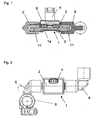
- FIG. 1 a battery current sensor constructed according to the invention is shown in a sectional view.
- the battery current sensor consists of a measuring sensor (1), with a formed by a metal strip measuring resistor (1 a) having in its central region a Kunststoffumspritzung (3), which forms part of a housing (2).
- the housing (2) has as a further housing part a housing cover (9), which is connected to the plastic extrusion (3), preferably by means of a laser welding, and which has a molded-on connector basket as part of a connector (4).
- the measuring resistor (1 a) has at its end portions on simple cylindrical projections (11) about whose central axis connecting elements (5, 6) are rotatably arranged. After determining the relative position of the connecting elements (5, 6) relative to the measuring sensor whose positions are locked by squeezing the joints.
- a first electrical connection means (5) is designed as a battery pole terminal (8) having an annular clamping element for connection to a cylindrical or cone-shaped battery pole.
- a second electrical connection means (6) which may be designed as a screw, plug or clamp connector, establishes the electrical and mechanical connection to a vehicle cable, not shown in the figure.
- the entire battery current flows through the measuring resistor (1 a), wherein the arranged within the plastic housing measuring circuit arrangement evaluates the voltage drop across the overmolded portion of the measuring resistor (1 a).
- a measurement signal corresponding to the current flow through the measuring resistor (1a) can be removed from the plug connector (4), which is formed on the cover (9) of the housing (2).
- the connecting means (5, 6) via the cylindrical projections (11) are first rotatably connected to the measuring sensor (1), the positioning of the connecting means (5, 6) relative to the measuring sensor (1) adapted very flexibly to the respective vehicle-specific circumstances become.
- vehicle-specific adapted connection means can be provided without structural changes to the measuring sensor (1) would have to be made. This makes a particularly simple and cost-effective adaptation of the battery current sensor to different vehicles possible.
- the rotatable connection between the connecting means (5, 6) and the measuring sensor for example by squeezing the connecting elements finally fixed.
- FIG. 3 shows some details of the battery sensor in a sectional drawing.
- the measuring sensor (1) integrally forms a strip-shaped measuring resistor (1a), at which a voltage proportional to the battery current drops, which is evaluated by a measuring circuit arrangement.
- The, not shown in the figure components of the measuring circuit arrangement are in this case arranged on a circuit carrier (10), which may be in particular a printed circuit board or a ceramic substrate.
- the measuring circuit receives the evaluation signal to be evaluated from the measuring sensor (1) via connecting means (7) between the measuring resistor (1 a) and the circuit carrier (10).
- connecting means (7) are provided for this, which connect the measuring resistor (1a) and the circuit carrier (10) both electrically and mechanically.
- the connecting means (7) are formed here as metal parts bent at right angles, of which in each case one connecting section (13) is fixed, for example via a solder connection or preferably via a welded connection, to the measuring resistor (1a).
- the with the circuit substrate (10) connected portions of the connecting elements (7) are formed as press-in contacts (12) which are inserted into recesses (15) of the circuit substrate with electrically conductive edge regions.
- the measuring circuit arrangement arranged on the circuit carrier (10) receives the voltage drop to be evaluated from the measuring resistor (1a). It is advantageous that possibly in the connection region of the press-fit contacts (12) and the circuit carrier (10) resulting minor contact resistance for the measurement result are not critical, since the voltage drop across the measuring resistor (1a) is preferably evaluated by a high-impedance measuring circuit arrangement.
- the thermal expansion of the measuring resistor (1a) which changes during operation due to changing temperature of the measuring resistor (1a) or the measuring sensor (1) does not lead to mechanical stresses in the connection to the circuit carrier (10).
- FIG. 5 shows a connecting element (7) enlarged in two views.
- the press-fit contact (12) inserted into a recess (15) of the circuit carrier (10) has the shape of an eyelet and, due to its resilient properties, is capable of thermal length changes of the measuring resistor (1a, see FIG FIG. 4 ) in its transverse direction.
- An at least limited resilient region (14) between the press-in contact (12) and the connecting portion (13) of the connecting element (7) compensates for the thermal change in length in the longitudinal direction of the measuring sensor (1).
- the embodiments of the invention are not limited to this embodiment.
- embodiments are possible in which the connecting means are firmly connected to the circuit carrier and resiliently connected to the measuring resistor.
- both sides of the connecting means are provided with resilient press-fit.
Landscapes
- Physics & Mathematics (AREA)
- General Physics & Mathematics (AREA)
- Measuring Instrument Details And Bridges, And Automatic Balancing Devices (AREA)
- Secondary Cells (AREA)
- Measurement Of Current Or Voltage (AREA)
- Control Of Electric Motors In General (AREA)
- Transmission And Conversion Of Sensor Element Output (AREA)
Claims (11)
- Détecteur de courant de batterie pour un véhicule automobile, avec un capteur de mesure (1), incorporé dans le circuit électrique de la batterie, et avec un circuit de mesure, relié au capteur de mesure (1), dans lequel au moins des éléments du circuit de mesure sont disposés sur un support de circuit (10), qui, fixement positionné, est raccordé électriquement et mécaniquement au capteur de mesure (1), par l'intermédiaire de moyens de liaison élastiques (7), qui, en raison de leurs propriétés élastiques, sont capables de compenser des changements de longueur thermiques du capteur de mesure (1), dans la direction transversale de celui-ci, caractérisé en ce que les moyens de liaison élastiques (7) présentent, chacun, au moins un contact à implanter par pression (12) élastique, par l'intermédiaire duquel ils sont reliés au support de circuit (10) et / ou au capteur de mesure (1).
- Détecteur de courant de batterie selon la revendication 1, caractérisé en ce que les moyens de liaison (7) présentent une section de liaison (13) pour la réalisation d'une liaison fixe au capteur de mesure (1) ou au support de circuit (10).
- Détecteur de courant de batterie selon la revendication 2, caractérisé en ce que la liaison fixe est une liaison brasée ou soudée.
- Détecteur de courant de batterie selon la revendication 1, caractérisé en ce que le contact à implanter par pression (12) forme une oreille élastique.
- Détecteur de courant de batterie selon la revendication 1, caractérisé en ce que le moyen de liaison (7) est conçu en tant que pièce métallique coudée.
- Détecteur de courant de batterie selon la revendication 1, caractérisé en ce que le moyen de liaison (7) est conçu en tant que pièce métallique, coudée. à angle droit.
- Détecteur de courant de batterie selon la revendication 2, caractérisé en ce que le moyen de liaison (7) présente, entre le contact à implanter par pression (12) et la section de liaison (13), une zone élastique (14).
- Détecteur de courant de batterie selon la revendication 1, caractérisé en ce que le support de circuit (10) est conçu en tant que plaquette de circuit imprimés ou en tant que substrat en céramique.
- Détecteur de courant de batterie selon l'une ou plusieurs des revendications précédentes, caractérisé en ce que plusieurs moyens de liaison (7) sont prévus et que les contacts à implanter par pression (12) sont en liaison avec le support de circuit et que les sections de liaison (13) sont reliées fixement au capteur de mesure (1).
- Détecteur de courant de batterie selon la revendication 1, caractérisé en ce que le capteur de mesure (1) est une résistance de mesure (1a).
- Détecteur de courant de batterie selon la revendication 10, caractérisé en ce que la résistance de mesure (1a) est formée par une bande métallique.
Applications Claiming Priority (2)
| Application Number | Priority Date | Filing Date | Title |
|---|---|---|---|
| DE102004053648A DE102004053648A1 (de) | 2004-11-03 | 2004-11-03 | Batteriestromsensor für ein Kraftfahrzeug |
| PCT/EP2005/011678 WO2006048232A1 (fr) | 2004-11-03 | 2005-11-02 | Capteur de courant de batterie pour véhicule automobile |
Publications (2)
| Publication Number | Publication Date |
|---|---|
| EP1807708A1 EP1807708A1 (fr) | 2007-07-18 |
| EP1807708B1 true EP1807708B1 (fr) | 2009-08-05 |
Family
ID=35645883
Family Applications (1)
| Application Number | Title | Priority Date | Filing Date |
|---|---|---|---|
| EP05800153A Expired - Lifetime EP1807708B1 (fr) | 2004-11-03 | 2005-11-02 | Capteur de courant de batterie pour véhicule automobile |
Country Status (8)
| Country | Link |
|---|---|
| US (1) | US7671755B2 (fr) |
| EP (1) | EP1807708B1 (fr) |
| JP (1) | JP2008519250A (fr) |
| CN (1) | CN100580460C (fr) |
| AT (1) | ATE438862T1 (fr) |
| DE (2) | DE102004053648A1 (fr) |
| ES (1) | ES2329700T3 (fr) |
| WO (1) | WO2006048232A1 (fr) |
Cited By (3)
| Publication number | Priority date | Publication date | Assignee | Title |
|---|---|---|---|---|
| WO2013037549A1 (fr) | 2011-09-16 | 2013-03-21 | Robert Bosch Gmbh | Résistance de mesure pour capteur de courant et unité capteur de courant |
| DE102013200580A1 (de) | 2013-01-16 | 2014-07-17 | Robert Bosch Gmbh | Messanordnung mit einem Messwiderstand |
| CN104583783B (zh) * | 2013-06-20 | 2018-09-11 | 古河电气工业株式会社 | 电池状态检测装置及其制造方法 |
Families Citing this family (35)
| Publication number | Priority date | Publication date | Assignee | Title |
|---|---|---|---|---|
| DE102004040575A1 (de) * | 2004-08-21 | 2006-02-23 | Abb Patent Gmbh | Einrichtung zum Messen von elektrischem Strom, Spannung und Temperatur an einem aus starrem Material bestehenden elektrischen Leiter |
| FR2879751B1 (fr) * | 2004-12-20 | 2007-02-23 | Johnson Controls Tech Co | Dispositif de mesure d'un courant circulant dans un cable |
| DE102005039587A1 (de) * | 2005-08-19 | 2007-02-22 | Robert Bosch Gmbh | Batteriesensoreinheit |
| DE102005057117A1 (de) * | 2005-11-30 | 2007-06-14 | Siemens Ag | Vorrichtung zum Erfassen einer elektrischen Größe eines Akkumulators und Verfahren zur Herstellung derselbigen |
| DE102006036247A1 (de) * | 2006-02-16 | 2007-08-23 | Kromberg & Schubert Gmbh & Co. Kg | Anschlusseinrichtung |
| US7688022B2 (en) | 2006-02-17 | 2010-03-30 | Lear Corporation | Energy management system for a vehicle |
| FR2903498B1 (fr) * | 2006-07-07 | 2008-10-17 | Valeo Electronique Sys Liaison | Capteur de surveillance de batterie resistant aux variations de temperatures. |
| DE102006038373A1 (de) * | 2006-08-12 | 2008-02-14 | Robert Bosch Gmbh | Elektrische Vorrichtung |
| DE102006053021A1 (de) | 2006-11-10 | 2008-05-15 | Hella Kgaa Hueck & Co. | Kraftfahrzeugsensor, insbesondere Batteriesensor mit Messwiderstand |
| DE102007017530A1 (de) * | 2007-04-13 | 2008-10-16 | Continental Automotive Gmbh | Kontaktierungssystem mit Vibrationsdämpfer für Strommessungsanordnungen |
| US8476864B2 (en) | 2007-06-13 | 2013-07-02 | Lear Corporation | Battery monitoring system |
| US7911319B2 (en) | 2008-02-06 | 2011-03-22 | Vishay Dale Electronics, Inc. | Resistor, and method for making same |
| EP2378293B1 (fr) * | 2010-03-31 | 2012-12-19 | Schniewindt GmbH & Co. KG | Dispositif de mesure destiné à mesurer un courant circulant dans un rail conducteur |
| DE102010028381A1 (de) * | 2010-04-29 | 2011-11-03 | Robert Bosch Gmbh | Elektronische Vorrichtung mit Presspassverbindung |
| DE102010029867B4 (de) | 2010-06-09 | 2023-03-23 | Zf Friedrichshafen Ag | Elektronische Baugruppe |
| JP2012177656A (ja) * | 2011-02-28 | 2012-09-13 | Yazaki Corp | シャント抵抗式電流センサ |
| JP5926495B2 (ja) * | 2011-04-05 | 2016-05-25 | 矢崎総業株式会社 | シャント抵抗式電流センサ |
| WO2013121872A1 (fr) | 2012-02-14 | 2013-08-22 | コーア株式会社 | Structure de connexion de borne pour résistance |
| DE102012203446A1 (de) * | 2012-03-05 | 2013-09-05 | Robert Bosch Gmbh | Elektronischer Batteriesensor |
| JP5918023B2 (ja) * | 2012-05-22 | 2016-05-18 | 矢崎総業株式会社 | シャント抵抗式電流センサ |
| DE102013210128A1 (de) * | 2013-03-05 | 2014-09-11 | Continental Automotive Gmbh | Einstückig ausgebildete Stromsensorvorrichtung |
| DE102013208375A1 (de) * | 2013-05-07 | 2014-11-13 | Continental Teves Ag & Co. Ohg | Mechanisches Halteelement zum Halten eines Stromsensors an einer Fahrzeugbatterie |
| DE102013104756B4 (de) | 2013-05-08 | 2025-07-31 | HELLA GmbH & Co. KGaA | Anordnung einer Sensorelektronik an einer Polklemme einer Batterie sowie Verfahren zur Herstellung einer derartigen Anordnung |
| EP2811305A1 (fr) * | 2013-06-04 | 2014-12-10 | Itron France | Dispositif de mesure d'électricité de barre omnibus |
| CN104604017B (zh) * | 2013-07-03 | 2018-05-25 | 古河电气工业株式会社 | 电池状态检测装置及其制造方法 |
| DE102014207759A1 (de) * | 2013-07-03 | 2015-01-08 | Continental Automotive Gmbh | Stromsensor-Shunt mit Bohrungen für Press-Fit-Pins |
| US9858784B2 (en) | 2014-09-29 | 2018-01-02 | Roost, Inc. | Battery-powered device having a battery and loud sound detector using passive sensing |
| US20160093924A1 (en) * | 2014-09-29 | 2016-03-31 | Zlick, Inc. | Communication-connected battery with expansion capability |
| DE102015216789A1 (de) * | 2015-09-02 | 2017-03-02 | Continental Automotive Gmbh | Anschlussvorrichtung zum Anschließen eines Messgerätes an einen Anschlusspol eines Energiespeichers eines Kraftfahrzeugs |
| DE102016204942A1 (de) * | 2016-03-24 | 2017-11-16 | Continental Automotive Gmbh | Deckel für ein Gehäuse, Batteriesensor und Verfahren zum Herstellen eines Batteriesensors |
| US20190369143A1 (en) * | 2018-06-05 | 2019-12-05 | Yazaki Corporation | Current sensor |
| DE102019121980A1 (de) * | 2019-01-22 | 2020-07-23 | Roman Nachsel | Hochstrom-Bauelement |
| JP7485721B2 (ja) * | 2022-05-11 | 2024-05-16 | 矢崎総業株式会社 | 電流検出装置 |
| EP4340133A1 (fr) * | 2022-09-13 | 2024-03-20 | TE Connectivity Germany GmbH | Élément de contact pour une résistance shunt, ensemble shunt et dispositif de mesure électrique |
| EP4700395A1 (fr) | 2024-08-22 | 2026-02-25 | Pollmann International GmbH | Système de mise en contact pour mettre en contact un module électronique avec une carte de circuit imprimé et résistance de mesure dotée d'un tel système de mise en contact |
Family Cites Families (16)
| Publication number | Priority date | Publication date | Assignee | Title |
|---|---|---|---|---|
| US4513499A (en) * | 1982-11-15 | 1985-04-30 | Frank Roldan | Method of making compliant pins |
| JPH0431740Y2 (fr) * | 1986-09-26 | 1992-07-30 | ||
| DE3865206D1 (de) * | 1988-11-07 | 1991-10-31 | Burndy Electra Nv | Kontaktstift. |
| JPH0483175A (ja) * | 1990-07-25 | 1992-03-17 | Mitsubishi Electric Corp | 電流検出装置 |
| DE19508133C2 (de) * | 1995-03-08 | 1997-02-13 | Kostal Leopold Gmbh & Co Kg | Stiftförmiges Kontaktelement |
| US5980267A (en) * | 1996-06-28 | 1999-11-09 | Intel Corporation | Connector scheme for a power pod power delivery system |
| JPH10208798A (ja) * | 1997-01-23 | 1998-08-07 | Kel Corp | 基板接続装置およびこの基板接続装置を用いたアクチュエータ取付ユニット |
| WO1999054744A1 (fr) * | 1998-04-17 | 1999-10-28 | Menico Ag | Pince amperemetrique pour batterie |
| US6304062B1 (en) * | 1999-10-28 | 2001-10-16 | Powersmart, Inc. | Shunt resistance device for monitoring battery state of charge |
| DE19961311A1 (de) * | 1999-12-18 | 2001-07-26 | Bayerische Motoren Werke Ag | Batteriesensorvorrichtung |
| DE10027519C2 (de) * | 2000-06-06 | 2002-04-25 | Siemens Ag | Trennschaltereinrichtung mit geringem Platzbedarf |
| ATE388505T1 (de) * | 2000-09-22 | 2008-03-15 | Shinetsu Polymer Co | Federelement, druckklemmenverbinder und halter mit sonde für elektroakustische komponente |
| JP3985182B2 (ja) * | 2000-11-01 | 2007-10-03 | 住友電装株式会社 | 電流センサ付きバッテリターミナル |
| CN2540637Y (zh) * | 2002-04-12 | 2003-03-19 | 大连第一互感器厂 | 电子式电流电压组合传感器 |
| JP3906786B2 (ja) * | 2002-11-27 | 2007-04-18 | 住友電装株式会社 | 回路基板用コネクタおよび端子圧入治具 |
| DE20318266U1 (de) * | 2003-11-26 | 2004-02-19 | Hella Kg Hueck & Co. | Vorrichtung zur Strommessung |
-
2004
- 2004-11-03 DE DE102004053648A patent/DE102004053648A1/de not_active Withdrawn
-
2005
- 2005-11-02 DE DE502005007864T patent/DE502005007864D1/de not_active Expired - Lifetime
- 2005-11-02 CN CN200580037411A patent/CN100580460C/zh not_active Expired - Fee Related
- 2005-11-02 JP JP2007538354A patent/JP2008519250A/ja active Pending
- 2005-11-02 AT AT05800153T patent/ATE438862T1/de not_active IP Right Cessation
- 2005-11-02 EP EP05800153A patent/EP1807708B1/fr not_active Expired - Lifetime
- 2005-11-02 ES ES05800153T patent/ES2329700T3/es not_active Expired - Lifetime
- 2005-11-02 WO PCT/EP2005/011678 patent/WO2006048232A1/fr not_active Ceased
-
2007
- 2007-04-20 US US11/788,701 patent/US7671755B2/en not_active Expired - Fee Related
Cited By (8)
| Publication number | Priority date | Publication date | Assignee | Title |
|---|---|---|---|---|
| WO2013037549A1 (fr) | 2011-09-16 | 2013-03-21 | Robert Bosch Gmbh | Résistance de mesure pour capteur de courant et unité capteur de courant |
| DE102012211733A1 (de) | 2011-09-16 | 2013-03-21 | Robert Bosch Gmbh | Messwiderstand für Stromsensor und Stromsensoreinheit |
| DE102012211701A1 (de) | 2011-09-16 | 2013-03-21 | Robert Bosch Gmbh | Messwiderstand für Stromsensor und Stromsensoreinheit |
| DE102012211749A1 (de) | 2011-09-16 | 2013-03-21 | Robert Bosch Gmbh | Messwiderstand für Stromsensor und Stromsensoreinheit |
| WO2013037548A1 (fr) | 2011-09-16 | 2013-03-21 | Robert Bosch Gmbh | Résistance de mesure pour capteur de courant et unité capteur de courant |
| WO2013037552A1 (fr) | 2011-09-16 | 2013-03-21 | Robert Bosch Gmbh | Résistance de mesure pour capteur de courant et unité capteur de courant |
| DE102013200580A1 (de) | 2013-01-16 | 2014-07-17 | Robert Bosch Gmbh | Messanordnung mit einem Messwiderstand |
| CN104583783B (zh) * | 2013-06-20 | 2018-09-11 | 古河电气工业株式会社 | 电池状态检测装置及其制造方法 |
Also Published As
| Publication number | Publication date |
|---|---|
| DE102004053648A1 (de) | 2006-05-04 |
| CN101052885A (zh) | 2007-10-10 |
| US7671755B2 (en) | 2010-03-02 |
| EP1807708A1 (fr) | 2007-07-18 |
| US20070200720A1 (en) | 2007-08-30 |
| CN100580460C (zh) | 2010-01-13 |
| WO2006048232A1 (fr) | 2006-05-11 |
| JP2008519250A (ja) | 2008-06-05 |
| ATE438862T1 (de) | 2009-08-15 |
| DE502005007864D1 (de) | 2009-09-17 |
| ES2329700T3 (es) | 2009-11-30 |
Similar Documents
| Publication | Publication Date | Title |
|---|---|---|
| EP1807708B1 (fr) | Capteur de courant de batterie pour véhicule automobile | |
| DE102007033182B4 (de) | Kraftfahrzeugbatteriesensorelement sowie Verfahren zur Herstellung eines Kraftfahrzeugbatteriesensorelements | |
| DE112013000968B4 (de) | Anschlussverbindungsaufbau für einen Widerstand | |
| DE202010005756U1 (de) | Elektronisches Bauelement, insbesondere Stromsensor | |
| DE102019203498B3 (de) | Passiver Stromsensor mit vereinfachter Geometrie | |
| EP1920264B1 (fr) | Capteur de batterie | |
| DE2815879A1 (de) | Vorrichtung zur ueberwachung der zusammensetzung der abgase eines verbrennungsprozesses | |
| EP0972288A1 (fr) | Procede pour produire un dispositif de detection destine a la mesure de temperatures | |
| DE112019002516T5 (de) | Nebenschlusswiderstands-Halterungsstruktur | |
| DE102004055849A1 (de) | Batteriesensorvorrichtung | |
| DE102017221612A1 (de) | Stromsensor und Verfahren zum Messen eines elektrischen Stroms | |
| DE29724000U1 (de) | Elektrischer Sensor, insbesondere Temperatur-Sensor, mit Leiterplatte | |
| DE102018123609B3 (de) | Temperaturmesseinrichtung, Steckverbinder, Herstellungsverfahren sowie Temperaturmessverfahren | |
| DE102005021959A1 (de) | Batteriestromsensor für ein Kraftfahrzeug | |
| DE102007006050B4 (de) | Anschlusseinrichtung | |
| DE102013220516B4 (de) | Messeinrichtung | |
| EP4012727A2 (fr) | Résistance de mesure, agencement de résistance et son procédé de fabrication | |
| EP4143515A1 (fr) | Réseau de capteurs pour un fluide, réservoir de fluide et utilisation du réseau de capteurs | |
| WO2000047963A1 (fr) | Capteur et son procede de fabrication | |
| EP3671241A1 (fr) | Module de résistance pour un capteur de batterie et capteur de batterie | |
| DE19746075A1 (de) | Meßwertaufnehmer zur Erfassung der elektrischen Leitfähigkeit eines flüssigen Mediums | |
| DE102011121902A1 (de) | Widerstand, insbesondere Strommesswiderstand | |
| DE102006054369A1 (de) | Sensoranordnung | |
| DE19715080C1 (de) | Thermometeranordnung mit einem Thermoelement | |
| DE102012105534A1 (de) | Vorrichtung zur Erfassung der Temperatur in einem Raum und ein Verfahren zur Herstellung einer solchen Vorrichtung |
Legal Events
| Date | Code | Title | Description |
|---|---|---|---|
| PUAI | Public reference made under article 153(3) epc to a published international application that has entered the european phase |
Free format text: ORIGINAL CODE: 0009012 |
|
| 17P | Request for examination filed |
Effective date: 20070413 |
|
| AK | Designated contracting states |
Kind code of ref document: A1 Designated state(s): AT BE BG CH CY CZ DE DK EE ES FI FR GB GR HU IE IS IT LI LT LU LV MC NL PL PT RO SE SI SK TR |
|
| 17Q | First examination report despatched |
Effective date: 20070831 |
|
| DAX | Request for extension of the european patent (deleted) | ||
| GRAP | Despatch of communication of intention to grant a patent |
Free format text: ORIGINAL CODE: EPIDOSNIGR1 |
|
| GRAS | Grant fee paid |
Free format text: ORIGINAL CODE: EPIDOSNIGR3 |
|
| GRAA | (expected) grant |
Free format text: ORIGINAL CODE: 0009210 |
|
| AK | Designated contracting states |
Kind code of ref document: B1 Designated state(s): AT BE BG CH CY CZ DE DK EE ES FI FR GB GR HU IE IS IT LI LT LU LV MC NL PL PT RO SE SI SK TR |
|
| REG | Reference to a national code |
Ref country code: GB Ref legal event code: FG4D Free format text: NOT ENGLISH |
|
| REG | Reference to a national code |
Ref country code: CH Ref legal event code: EP |
|
| REG | Reference to a national code |
Ref country code: IE Ref legal event code: FG4D |
|
| REF | Corresponds to: |
Ref document number: 502005007864 Country of ref document: DE Date of ref document: 20090917 Kind code of ref document: P |
|
| REG | Reference to a national code |
Ref country code: ES Ref legal event code: FG2A Ref document number: 2329700 Country of ref document: ES Kind code of ref document: T3 |
|
| LTIE | Lt: invalidation of european patent or patent extension |
Effective date: 20090805 |
|
| PG25 | Lapsed in a contracting state [announced via postgrant information from national office to epo] |
Ref country code: FI Free format text: LAPSE BECAUSE OF FAILURE TO SUBMIT A TRANSLATION OF THE DESCRIPTION OR TO PAY THE FEE WITHIN THE PRESCRIBED TIME-LIMIT Effective date: 20090805 Ref country code: SE Free format text: LAPSE BECAUSE OF FAILURE TO SUBMIT A TRANSLATION OF THE DESCRIPTION OR TO PAY THE FEE WITHIN THE PRESCRIBED TIME-LIMIT Effective date: 20090805 Ref country code: IS Free format text: LAPSE BECAUSE OF FAILURE TO SUBMIT A TRANSLATION OF THE DESCRIPTION OR TO PAY THE FEE WITHIN THE PRESCRIBED TIME-LIMIT Effective date: 20091205 Ref country code: LT Free format text: LAPSE BECAUSE OF FAILURE TO SUBMIT A TRANSLATION OF THE DESCRIPTION OR TO PAY THE FEE WITHIN THE PRESCRIBED TIME-LIMIT Effective date: 20090805 |
|
| NLV1 | Nl: lapsed or annulled due to failure to fulfill the requirements of art. 29p and 29m of the patents act | ||
| PG25 | Lapsed in a contracting state [announced via postgrant information from national office to epo] |
Ref country code: NL Free format text: LAPSE BECAUSE OF FAILURE TO SUBMIT A TRANSLATION OF THE DESCRIPTION OR TO PAY THE FEE WITHIN THE PRESCRIBED TIME-LIMIT Effective date: 20090805 Ref country code: LV Free format text: LAPSE BECAUSE OF FAILURE TO SUBMIT A TRANSLATION OF THE DESCRIPTION OR TO PAY THE FEE WITHIN THE PRESCRIBED TIME-LIMIT Effective date: 20090805 Ref country code: SI Free format text: LAPSE BECAUSE OF FAILURE TO SUBMIT A TRANSLATION OF THE DESCRIPTION OR TO PAY THE FEE WITHIN THE PRESCRIBED TIME-LIMIT Effective date: 20090805 Ref country code: PL Free format text: LAPSE BECAUSE OF FAILURE TO SUBMIT A TRANSLATION OF THE DESCRIPTION OR TO PAY THE FEE WITHIN THE PRESCRIBED TIME-LIMIT Effective date: 20090805 |
|
| REG | Reference to a national code |
Ref country code: IE Ref legal event code: FD4D |
|
| PG25 | Lapsed in a contracting state [announced via postgrant information from national office to epo] |
Ref country code: BG Free format text: LAPSE BECAUSE OF FAILURE TO SUBMIT A TRANSLATION OF THE DESCRIPTION OR TO PAY THE FEE WITHIN THE PRESCRIBED TIME-LIMIT Effective date: 20091105 Ref country code: PT Free format text: LAPSE BECAUSE OF FAILURE TO SUBMIT A TRANSLATION OF THE DESCRIPTION OR TO PAY THE FEE WITHIN THE PRESCRIBED TIME-LIMIT Effective date: 20091205 |
|
| PG25 | Lapsed in a contracting state [announced via postgrant information from national office to epo] |
Ref country code: RO Free format text: LAPSE BECAUSE OF FAILURE TO SUBMIT A TRANSLATION OF THE DESCRIPTION OR TO PAY THE FEE WITHIN THE PRESCRIBED TIME-LIMIT Effective date: 20090805 Ref country code: EE Free format text: LAPSE BECAUSE OF FAILURE TO SUBMIT A TRANSLATION OF THE DESCRIPTION OR TO PAY THE FEE WITHIN THE PRESCRIBED TIME-LIMIT Effective date: 20090805 Ref country code: DK Free format text: LAPSE BECAUSE OF FAILURE TO SUBMIT A TRANSLATION OF THE DESCRIPTION OR TO PAY THE FEE WITHIN THE PRESCRIBED TIME-LIMIT Effective date: 20090805 Ref country code: IE Free format text: LAPSE BECAUSE OF FAILURE TO SUBMIT A TRANSLATION OF THE DESCRIPTION OR TO PAY THE FEE WITHIN THE PRESCRIBED TIME-LIMIT Effective date: 20090805 Ref country code: CZ Free format text: LAPSE BECAUSE OF FAILURE TO SUBMIT A TRANSLATION OF THE DESCRIPTION OR TO PAY THE FEE WITHIN THE PRESCRIBED TIME-LIMIT Effective date: 20090805 |
|
| BERE | Be: lapsed |
Owner name: LEOPOLD KOSTAL G.M.B.H. & CO. KG Effective date: 20091130 |
|
| PG25 | Lapsed in a contracting state [announced via postgrant information from national office to epo] |
Ref country code: SK Free format text: LAPSE BECAUSE OF FAILURE TO SUBMIT A TRANSLATION OF THE DESCRIPTION OR TO PAY THE FEE WITHIN THE PRESCRIBED TIME-LIMIT Effective date: 20090805 |
|
| PLBE | No opposition filed within time limit |
Free format text: ORIGINAL CODE: 0009261 |
|
| STAA | Information on the status of an ep patent application or granted ep patent |
Free format text: STATUS: NO OPPOSITION FILED WITHIN TIME LIMIT |
|
| PG25 | Lapsed in a contracting state [announced via postgrant information from national office to epo] |
Ref country code: MC Free format text: LAPSE BECAUSE OF NON-PAYMENT OF DUE FEES Effective date: 20091130 |
|
| REG | Reference to a national code |
Ref country code: CH Ref legal event code: PL |
|
| 26N | No opposition filed |
Effective date: 20100507 |
|
| PG25 | Lapsed in a contracting state [announced via postgrant information from national office to epo] |
Ref country code: CH Free format text: LAPSE BECAUSE OF NON-PAYMENT OF DUE FEES Effective date: 20091130 Ref country code: GR Free format text: LAPSE BECAUSE OF FAILURE TO SUBMIT A TRANSLATION OF THE DESCRIPTION OR TO PAY THE FEE WITHIN THE PRESCRIBED TIME-LIMIT Effective date: 20091106 Ref country code: BE Free format text: LAPSE BECAUSE OF NON-PAYMENT OF DUE FEES Effective date: 20091130 Ref country code: LI Free format text: LAPSE BECAUSE OF NON-PAYMENT OF DUE FEES Effective date: 20091130 |
|
| PG25 | Lapsed in a contracting state [announced via postgrant information from national office to epo] |
Ref country code: AT Free format text: LAPSE BECAUSE OF NON-PAYMENT OF DUE FEES Effective date: 20091102 |
|
| PG25 | Lapsed in a contracting state [announced via postgrant information from national office to epo] |
Ref country code: LU Free format text: LAPSE BECAUSE OF NON-PAYMENT OF DUE FEES Effective date: 20091102 |
|
| PG25 | Lapsed in a contracting state [announced via postgrant information from national office to epo] |
Ref country code: HU Free format text: LAPSE BECAUSE OF FAILURE TO SUBMIT A TRANSLATION OF THE DESCRIPTION OR TO PAY THE FEE WITHIN THE PRESCRIBED TIME-LIMIT Effective date: 20100206 |
|
| PG25 | Lapsed in a contracting state [announced via postgrant information from national office to epo] |
Ref country code: TR Free format text: LAPSE BECAUSE OF FAILURE TO SUBMIT A TRANSLATION OF THE DESCRIPTION OR TO PAY THE FEE WITHIN THE PRESCRIBED TIME-LIMIT Effective date: 20090805 |
|
| PG25 | Lapsed in a contracting state [announced via postgrant information from national office to epo] |
Ref country code: CY Free format text: LAPSE BECAUSE OF FAILURE TO SUBMIT A TRANSLATION OF THE DESCRIPTION OR TO PAY THE FEE WITHIN THE PRESCRIBED TIME-LIMIT Effective date: 20090805 |
|
| REG | Reference to a national code |
Ref country code: FR Ref legal event code: PLFP Year of fee payment: 11 |
|
| PGFP | Annual fee paid to national office [announced via postgrant information from national office to epo] |
Ref country code: GB Payment date: 20151116 Year of fee payment: 11 Ref country code: IT Payment date: 20151104 Year of fee payment: 11 |
|
| PGFP | Annual fee paid to national office [announced via postgrant information from national office to epo] |
Ref country code: FR Payment date: 20151113 Year of fee payment: 11 Ref country code: ES Payment date: 20151111 Year of fee payment: 11 |
|
| REG | Reference to a national code |
Ref country code: DE Ref legal event code: R084 Ref document number: 502005007864 Country of ref document: DE |
|
| GBPC | Gb: european patent ceased through non-payment of renewal fee |
Effective date: 20161102 |
|
| REG | Reference to a national code |
Ref country code: FR Ref legal event code: ST Effective date: 20170731 |
|
| PG25 | Lapsed in a contracting state [announced via postgrant information from national office to epo] |
Ref country code: IT Free format text: LAPSE BECAUSE OF NON-PAYMENT OF DUE FEES Effective date: 20161102 Ref country code: FR Free format text: LAPSE BECAUSE OF NON-PAYMENT OF DUE FEES Effective date: 20161130 |
|
| PG25 | Lapsed in a contracting state [announced via postgrant information from national office to epo] |
Ref country code: GB Free format text: LAPSE BECAUSE OF NON-PAYMENT OF DUE FEES Effective date: 20161102 |
|
| PG25 | Lapsed in a contracting state [announced via postgrant information from national office to epo] |
Ref country code: ES Free format text: LAPSE BECAUSE OF NON-PAYMENT OF DUE FEES Effective date: 20161103 |
|
| REG | Reference to a national code |
Ref country code: ES Ref legal event code: FD2A Effective date: 20181123 |
|
| PGFP | Annual fee paid to national office [announced via postgrant information from national office to epo] |
Ref country code: DE Payment date: 20191122 Year of fee payment: 15 |
|
| REG | Reference to a national code |
Ref country code: DE Ref legal event code: R081 Ref document number: 502005007864 Country of ref document: DE Owner name: KOSTAL AUTOMOBIL ELEKTRIK GMBH & CO. KG, DE Free format text: FORMER OWNER: LEOPOLD KOSTAL GMBH & CO. KG, 58513 LUEDENSCHEID, DE |
|
| REG | Reference to a national code |
Ref country code: DE Ref legal event code: R119 Ref document number: 502005007864 Country of ref document: DE |
|
| PG25 | Lapsed in a contracting state [announced via postgrant information from national office to epo] |
Ref country code: DE Free format text: LAPSE BECAUSE OF NON-PAYMENT OF DUE FEES Effective date: 20210601 |