EP1812705B1 - Vehicule a moteur turbo diesel et recyclage des gaz d'echappement - Google Patents
Vehicule a moteur turbo diesel et recyclage des gaz d'echappement Download PDFInfo
- Publication number
- EP1812705B1 EP1812705B1 EP05802362A EP05802362A EP1812705B1 EP 1812705 B1 EP1812705 B1 EP 1812705B1 EP 05802362 A EP05802362 A EP 05802362A EP 05802362 A EP05802362 A EP 05802362A EP 1812705 B1 EP1812705 B1 EP 1812705B1
- Authority
- EP
- European Patent Office
- Prior art keywords
- exhaust gas
- exhaust
- valve
- flap
- branch valve
- Prior art date
- Legal status (The legal status is an assumption and is not a legal conclusion. Google has not performed a legal analysis and makes no representation as to the accuracy of the status listed.)
- Revoked
Links
Images


Classifications
-
- F—MECHANICAL ENGINEERING; LIGHTING; HEATING; WEAPONS; BLASTING
- F02—COMBUSTION ENGINES; HOT-GAS OR COMBUSTION-PRODUCT ENGINE PLANTS
- F02D—CONTROLLING COMBUSTION ENGINES
- F02D9/00—Controlling engines by throttling air or fuel-and-air induction conduits or exhaust conduits
- F02D9/04—Controlling engines by throttling air or fuel-and-air induction conduits or exhaust conduits concerning exhaust conduits
-
- F—MECHANICAL ENGINEERING; LIGHTING; HEATING; WEAPONS; BLASTING
- F02—COMBUSTION ENGINES; HOT-GAS OR COMBUSTION-PRODUCT ENGINE PLANTS
- F02M—SUPPLYING COMBUSTION ENGINES IN GENERAL WITH COMBUSTIBLE MIXTURES OR CONSTITUENTS THEREOF
- F02M26/00—Engine-pertinent apparatus for adding exhaust gases to combustion-air, main fuel or fuel-air mixture, e.g. by exhaust gas recirculation [EGR] systems
- F02M26/02—EGR systems specially adapted for supercharged engines
- F02M26/04—EGR systems specially adapted for supercharged engines with a single turbocharger
- F02M26/06—Low pressure loops, i.e. wherein recirculated exhaust gas is taken out from the exhaust downstream of the turbocharger turbine and reintroduced into the intake system upstream of the compressor
-
- F—MECHANICAL ENGINEERING; LIGHTING; HEATING; WEAPONS; BLASTING
- F02—COMBUSTION ENGINES; HOT-GAS OR COMBUSTION-PRODUCT ENGINE PLANTS
- F02M—SUPPLYING COMBUSTION ENGINES IN GENERAL WITH COMBUSTIBLE MIXTURES OR CONSTITUENTS THEREOF
- F02M26/00—Engine-pertinent apparatus for adding exhaust gases to combustion-air, main fuel or fuel-air mixture, e.g. by exhaust gas recirculation [EGR] systems
- F02M26/02—EGR systems specially adapted for supercharged engines
- F02M26/09—Constructional details, e.g. structural combinations of EGR systems and supercharger systems; Arrangement of the EGR and supercharger systems with respect to the engine
- F02M26/10—Constructional details, e.g. structural combinations of EGR systems and supercharger systems; Arrangement of the EGR and supercharger systems with respect to the engine having means to increase the pressure difference between the exhaust and intake system, e.g. venturis, variable geometry turbines, check valves using pressure pulsations or throttles in the air intake or exhaust system
-
- F—MECHANICAL ENGINEERING; LIGHTING; HEATING; WEAPONS; BLASTING
- F02—COMBUSTION ENGINES; HOT-GAS OR COMBUSTION-PRODUCT ENGINE PLANTS
- F02M—SUPPLYING COMBUSTION ENGINES IN GENERAL WITH COMBUSTIBLE MIXTURES OR CONSTITUENTS THEREOF
- F02M26/00—Engine-pertinent apparatus for adding exhaust gases to combustion-air, main fuel or fuel-air mixture, e.g. by exhaust gas recirculation [EGR] systems
- F02M26/13—Arrangement or layout of EGR passages, e.g. in relation to specific engine parts or for incorporation of accessories
- F02M26/14—Arrangement or layout of EGR passages, e.g. in relation to specific engine parts or for incorporation of accessories in relation to the exhaust system
- F02M26/16—Arrangement or layout of EGR passages, e.g. in relation to specific engine parts or for incorporation of accessories in relation to the exhaust system with EGR valves located at or near the connection to the exhaust system
-
- F—MECHANICAL ENGINEERING; LIGHTING; HEATING; WEAPONS; BLASTING
- F02—COMBUSTION ENGINES; HOT-GAS OR COMBUSTION-PRODUCT ENGINE PLANTS
- F02M—SUPPLYING COMBUSTION ENGINES IN GENERAL WITH COMBUSTIBLE MIXTURES OR CONSTITUENTS THEREOF
- F02M26/00—Engine-pertinent apparatus for adding exhaust gases to combustion-air, main fuel or fuel-air mixture, e.g. by exhaust gas recirculation [EGR] systems
- F02M26/52—Systems for actuating EGR valves
- F02M26/59—Systems for actuating EGR valves using positive pressure actuators; Check valves therefor
- F02M26/61—Systems for actuating EGR valves using positive pressure actuators; Check valves therefor in response to exhaust pressure
-
- F—MECHANICAL ENGINEERING; LIGHTING; HEATING; WEAPONS; BLASTING
- F02—COMBUSTION ENGINES; HOT-GAS OR COMBUSTION-PRODUCT ENGINE PLANTS
- F02M—SUPPLYING COMBUSTION ENGINES IN GENERAL WITH COMBUSTIBLE MIXTURES OR CONSTITUENTS THEREOF
- F02M26/00—Engine-pertinent apparatus for adding exhaust gases to combustion-air, main fuel or fuel-air mixture, e.g. by exhaust gas recirculation [EGR] systems
- F02M26/65—Constructional details of EGR valves
- F02M26/70—Flap valves; Rotary valves; Sliding valves; Resilient valves
-
- F—MECHANICAL ENGINEERING; LIGHTING; HEATING; WEAPONS; BLASTING
- F02—COMBUSTION ENGINES; HOT-GAS OR COMBUSTION-PRODUCT ENGINE PLANTS
- F02B—INTERNAL-COMBUSTION PISTON ENGINES; COMBUSTION ENGINES IN GENERAL
- F02B29/00—Engines characterised by provision for charging or scavenging not provided for in groups F02B25/00, F02B27/00 or F02B33/00 - F02B39/00; Details thereof
- F02B29/04—Cooling of air intake supply
- F02B29/0406—Layout of the intake air cooling or coolant circuit
-
- Y—GENERAL TAGGING OF NEW TECHNOLOGICAL DEVELOPMENTS; GENERAL TAGGING OF CROSS-SECTIONAL TECHNOLOGIES SPANNING OVER SEVERAL SECTIONS OF THE IPC; TECHNICAL SUBJECTS COVERED BY FORMER USPC CROSS-REFERENCE ART COLLECTIONS [XRACs] AND DIGESTS
- Y02—TECHNOLOGIES OR APPLICATIONS FOR MITIGATION OR ADAPTATION AGAINST CLIMATE CHANGE
- Y02T—CLIMATE CHANGE MITIGATION TECHNOLOGIES RELATED TO TRANSPORTATION
- Y02T10/00—Road transport of goods or passengers
- Y02T10/10—Internal combustion engine [ICE] based vehicles
- Y02T10/12—Improving ICE efficiencies
Definitions
- the present invention relates to a vehicle according to the preamble of claim 1.
- Such a vehicle is out of the EP 1 340 904 A1 known.
- the relevant state of the art further includes the US 5,740,785 as well as the EP 1 621 755 A2 ,
- the present invention relates to a vehicle with a diesel engine according to the preamble of claim 1.
- the prior art is diesel engines equipped with a turbocharger, a charge air cooler and an exhaust gas recirculation device.
- Modern diesel vehicles are increasingly equipped with soot particle filters.
- the exhaust gas "branched off" into the intake tract usually takes place before the exhaust gas turbocharger.
- the "recirculated” exhaust gas is then usually fed into the intake tract after the intercooler.
- the problem here is on the one hand, that the recirculated exhaust gas is contaminated with diesel particles. Since the removal of the recirculating exhaust gas takes place in front of the exhaust gas turbocharger, further reduces the flowing over the turbine of the exhaust gas turbocharger mass flow, which adversely affects the dynamics of the exhaust gas turbocharger.
- Another disadvantage is that when an introduction of the exhaust gas after the intercooler of the intercooler can not be used to cool the exhaust gas.
- the object of the invention is to provide a vehicle with a turbo diesel engine with an improved exhaust gas recirculation device.
- the invention is based on a vehicle with a diesel engine and a turbocharger.
- the compressor of the turbocharger is located in the intake tract of the diesel engine, sucks the fresh air, compressed and fed via a charge air cooler to the diesel engine.
- the compressor rotationally coupled turbine of the exhaust gas turbocharger is arranged in the exhaust tract of the diesel engine with the compressor rotationally coupled turbine of the exhaust gas turbocharger.
- a soot particle filter is arranged after the turbine of the exhaust gas turbocharger.
- a "branch valve” is arranged, which is also referred to below as "scoop valve".
- the exhaust tract an exhaust gas partial volume flow can be removed and fed to the intake. Since the branching or scooping valve is arranged after the soot particle filter, the exhaust gas supplied to the intake tract is free or virtually free of soot particles, which has the advantage that the recirculated exhaust gas does not contaminate the intake tract. Another advantage is that the entire exhaust gas volume flow flows through the turbine of the exhaust gas turbocharger, so that the kinetic energy of the exhaust gas can be optimally utilized.
- the exhaust branched off via the branch valve or scoop valve can be supplied to the intake tract upstream of the compressor, for example. Alternatively, the exhaust gas to be recirculated can also be supplied to the intake tract directly via the compressor housing.
- the branch valve or scoop valve preferably has an unconfirmed basic position in which it tightly seals the fluid connection to the intake tract, so that the entire exhaust gas emitted by the engine can flow unhindered into the exhaust system.
- the "exhaust gas recirculation channel" i. the fluid connection between the branch valve and the intake tract more and more open while the exhaust passage in the direction of the tailpipe more and more closed, so that the exhaust back pressure increases and thus the purging gradient and ultimately the representable exhaust gas recirculation rate is increased.
- the branch or scoop valve and the lines for the return of exhaust gas from the exhaust tract into the intake tract and the radiator for cooling the recirculated exhaust gas are attached directly to the particulate filter.
- the exhaust manifold, the exhaust gas turbocharger, the soot particle filter and the branch or scoop valve form a preassembled or preassembled structural unit.
- FIG. 1 shows a schematic representation of a turbo diesel engine 1 with an intake tract 2 and an exhaust tract 3.
- a compressor 4 is arranged, which is rotationally coupled to a turbine 5, which is arranged in the exhaust tract 3.
- the compressor 4 and the turbine 5 form an exhaust turbocharger.
- the turbine 5 is traversed by exhaust gas of the diesel engine 1 and drives the compressor 4.
- the compressor 4 sucks fresh air via an air filter (not shown here), compresses it and feeds the compressed fresh air via a charge air cooler 6, in which the compressed fresh air is cooled, to the diesel engine 1.
- a soot particle filter 7 is arranged after the turbine 5, which filters out a large part of the soot particles contained in the exhaust gas.
- a branching or scooping valve 8 is arranged downstream of the soot particle filter.
- the branching or scooping valve 8 has a basic position in which the entire exhaust gas volume flow flows out of the exhaust gas tract via a tailpipe not shown here in detail.
- Via a connecting line 9, the branch or scoop valve is connected to the intake tract 2.
- the connecting line 9 opens in the intake in front of the compressor 4 in the intake tract. With increasing opening of the branching or scoop valve 8, the flow path to the connecting line 9 is increasingly opened and the flow cross-section towards the tailpipe increasingly closed.
- the scoop valve 8 is an electronically controllable scoop valve whose valve position is controlled in dependence on various engine or operating state parameters. Since the recirculated exhaust gas is taken from the exhaust tract 3 after the soot particle filter 7, it can be fed to the intake tract 2 easily before the compressor 4 and the intercooler 6.
- FIG. 2 shows a variant of the invention.
- the branch or scoop valve 8 is connected via the connecting line 9 directly to the compressor 4.
- the recirculated exhaust gas is thus introduced directly via the compressor housing (not shown) in the compressor 4.
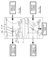
- FIG. 3 shows a schematic representation of a cross section of the branch or scoop valve 8.
- the branch or the scoop valve 8 has a pivotally mounted flap 10. In a basic position, the flap 10 blocks the fluid connection between the exhaust gas tract and the connecting line 9 (see. FIG. 1 . 2 ).
- the branch or scoop valve 8 can be partially or completely opened by an electronics.
- a partial volume flow 11 of the exhaust gas flow rate is diverted and fed via a connecting line 9 to the intake tract 2.
- the remaining exhaust gas volume flow 12 flows past the flap 10 in the direction of a tailpipe not shown here.
- FIG. 4 shows the branch or the scoop valve 8 of FIG. 3 in perspective view.
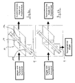
- FIGS. 5a and 5b show an embodiment of a branch or scoop valve 8, which is designed as a "centrally mounted flap" 10.
- the flap 10 has a first flap wing 10a and a transversely projecting flap arm 10b, at the free end of a flap plate 10c is arranged.
- the flap plate 10c is provided for closing the connecting line 9 (see. Fig. 5a ).
- the flap 10 is mounted on a pivot axis 13.
- the pivot axis is connected approximately in the middle of the flap wing 10a with the flap wing 10a.
- the Figures 6a and 6b show an embodiment with a rotatable or pivotally arranged double flap.
- the double flap 10 is supported by an adjusting shaft 14.
- the adjusting shaft 14 passes through the channel connecting the exhaust gas turbocharger with the exhaust system obliquely.
- the double flap 10 has a first flap wing 10a and a second flap wing 10b.
- the flap wing 10a is provided for closing or opening the channel connecting the exhaust gas turbocharger to the exhaust system.
- the flap wing 10b is for closing or opening the connecting channel 9 (see. Fig. 1 ) intended.
- the two flap wings 10a, 10b are not arranged perpendicular with respect to the adjusting axis 14, but at an angle with respect to the adjusting axis 14, ie the angle between the adjusting axis 14 and the planes of the flap wings 10a, 10b is not equal to 90 °.
- the planes of the flap wings 10a, 10b with the adjusting axis 14 each enclose an angle of approximately 45 °. Due to the oblique Anornung the flap wings 10a, 10b on the adjusting axis 14 lift the Flow forces substantially, allowing an adjustment with low actuating forces.
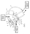
- FIG. 7 shows an embodiment in which in the exhaust passage, which the turbocharger 7 (see. Fig. 1 ) connects to the exhaust system, a branch or scoop valve 8 is arranged, which is designed as a pivotable flap 10.
- the flap 10 is pivotally mounted at its "end" on a pivot axis 13.
- the flap 10 In the in FIG. 7 shown position, the flap 10 is almost completely open. In this open position, the majority of the volume flow coming from the exhaust gas turbocharger is conducted into the connecting line 9. About the connecting line 9, the "branched off exhaust gas” is directed into the intake tract (see. Fig. 1 ).
- the exhaust passage which is the turbocharger 7 (see. Fig. 1 ) connects to the exhaust system, shut off from the connection channel. In this "blocking position" the exhaust gas coming from the exhaust gas turbocharger is completely discharged via the exhaust system to the environment, ie there is no exhaust gas directed to the intake.
- the flap 10 is connected to a control lever 15. By pivoting the control lever 15, the flap 10 can be opened or closed.
- the adjusting lever 15 in turn is connected via a hinge 16 hingedly connected to an actuating rod 17.
- the control rod 17 is connected to the diaphragm 18 of a first pressure cell 19, which has a first pressure chamber 20 and a second pressure chamber 21.
- the control rod 17 is further connected to the diaphragm (not visible) of a second pressure cell 22, which also, according to the pressure cell 19 has a first, ie upper pressure chamber 23 and a second, ie lower pressure chamber, in the illustration shown here through the wall the second pressure cell 22 is covered.
- the control rod thus extends through the two pressure cans 19, 22 therethrough.
- the first pressure chamber 23 of the second pressure cell 22 has a vacuum port 24 which is connected to the engine (not shown).
- the second pressure cell 22 is provided for controlling the position of the flap 10. If the negative pressure in the pressure chamber 23 is large, that is, if the absolute pressure in the pressure chamber 23 is small, then the pressure prevailing in the second, not to be recognized pressure chamber pushes the diaphragm of the second pressure cell and the associated control rod 10 relatively far " to the top ", which causes the flap 10 in the in FIG. 7 shown opening position is pivoted. Conversely, in the pressure chamber 23, a greater pressure prevails, the control rod is moved downward, which causes the flap 10 is further or completely closed.
- the flap 10 is opened, formed in an exhaust passage portion 25, which, seen in the flow direction of the exhaust gas, is located in front of the flap 10, an overpressure with respect to an exhaust passage portion 26, which, viewed in the flow direction of the exhaust gas, is located after the flap 10 .
- an overpressure with respect to an exhaust passage portion 26, which, viewed in the flow direction of the exhaust gas, is located after the flap 10 If the flap 10 is to be closed, then the moment created by the dynamic pressure arising at the flap 10 must be overcome.
- a pressure compensation device is provided, which is essentially formed by the first pressure cell 19.
- the first pressure chamber 20 of the first pressure cell 19 is connected via a hose 27 with the exhaust gas passage portion 25, which, viewed in the flow direction of the exhaust gas, is located in front of the flap 10.
- the second pressure chamber 21 of the first pressure cell 19 is connected via a hose 28 to the exhaust gas passage section 26, which, viewed in the flow direction of the exhaust gas, lies after the flap 10.
- the flap 10 When the flap 10 is open (see. Fig. 7 ) prevails in the pressure chamber 20 thus prevailing in the exhaust duct section 25 pressure and in the pressure chamber 21 of the pressure prevailing in the exhaust duct section 26 pressure.
- Of the Pressure in the pressure chamber 20 is thus greater than the pressure in the pressure chamber 21 when the flap 10 is open.
- the pressure difference exerts on the control rod 17 a downwardly acting force, which counteracts the "momentum" via the lever 15.
- the flap 10 can thus be closed with a relatively small closing moment.
Landscapes
- Engineering & Computer Science (AREA)
- Chemical & Material Sciences (AREA)
- Combustion & Propulsion (AREA)
- Mechanical Engineering (AREA)
- General Engineering & Computer Science (AREA)
- Exhaust-Gas Circulating Devices (AREA)
- Supercharger (AREA)
Claims (6)
- Véhicule comportant un moteur Diesel (1) ayant les caractéristiques suivantes:- un collecteur d'admission (2) par l'intermédiaire duquel de l'air frais est aspiré à travers un compresseur (4) d'un turbocompresseur de gaz d'échappement (4, 5) pour être comprimé et être fourni au moteur Diesel (1) par l'intermédiaire d'un radiateur d'air d'alimentation (6),- une installation de gaz d'échappement (3) dans laquelle les gaz d'échappement sortant du moteur Diesel (1) entraînent une turbine (5) du turbocompresseur de gaz d'échappement (4, 5) couplée en rotation au compresseur (4) et en aval de la turbine (5) les gaz d'échappement traversent un filtre à particules (7),- une vanne (8) installée en aval du filtre à particules (7) dans le sens de passage des gaz d'échappement, et qui coopère par liaison fluidique avec le collecteur d'admission (2),- la vanne (8) fournissant au collecteur d'admission (2) un débit volumique partiel des gaz d'échappement,caractérisé en ce que
la vanne (8) est une vanne de dérivation (8) montée dans l'installation de gaz d'échappement (3) et par l'intermédiaire de la vanne de dérivation (8) on prélève une fraction de débit volumique de gaz d'échappement du conduit de gaz d'échappement de l'installation de gaz d'échappement (3) pour fournir cette fraction de gaz d'échappement au collecteur d'admission (2), et
la vanne de dérivation (8) présente une position de base non actionnée dans laquelle elle ferme la communication de fluide vers le collecteur d'admission (2). - Véhicule selon la revendication 1,
caractérisé en ce que
la vanne de dérivation est branchée sur le collecteur d'admission (2) en amont du compresseur (4) selon le sens de passage de l'air aspiré par le collecteur d'admission (2). - Véhicule selon la revendication 1,
caractérisé en ce que
la vanne de dérivation (8) est reliée par une liaison fluidique directement avec le compresseur (4) par une conduite de liaison (9). - Véhicule selon l'une des revendications précédentes,
caractérisé en ce que
la vanne de dérivation (8) présente plusieurs positions d'ouverture et l'ouverture croissante de la vanne de dérivation (8) augmente la section de passage de la liaison fluidique vers le collecteur d'admission et en même temps diminue la section de passage de l'installation de gaz d'échappement (3) vers le tuyau d'échappement et réciproquement. - Véhicule selon l'une des revendications précédentes,
caractérisé en ce que
la vanne de dérivation (8) comporte un volet de vanne (10), basculant, et la position basculée du volet de vanne définit la section de passage vers le collecteur d'admission (2) et la section de passage vers le tuyau d'échappement de l'installation de gaz d'échappement (3). - Véhicule selon l'une des revendications précédentes,
caractérisé par
un collecteur d'échappement relié au moteur Diesel (1) et qui avec le turbocompresseur de gaz d'échappement (4, 5), le filtre à particules (7) et la vanne de dérivation (8) sont reliés en un ensemble de construction.
Applications Claiming Priority (2)
| Application Number | Priority Date | Filing Date | Title |
|---|---|---|---|
| DE102004055846.9A DE102004055846B4 (de) | 2004-11-19 | 2004-11-19 | Fahrzeug mit Turbo-Dieselmotor und Abgasrückführung |
| PCT/EP2005/011330 WO2006056279A1 (fr) | 2004-11-19 | 2005-10-21 | Vehicule a moteur turbo diesel et recyclage des gaz d'echappement |
Publications (2)
| Publication Number | Publication Date |
|---|---|
| EP1812705A1 EP1812705A1 (fr) | 2007-08-01 |
| EP1812705B1 true EP1812705B1 (fr) | 2008-10-01 |
Family
ID=35519913
Family Applications (1)
| Application Number | Title | Priority Date | Filing Date |
|---|---|---|---|
| EP05802362A Revoked EP1812705B1 (fr) | 2004-11-19 | 2005-10-21 | Vehicule a moteur turbo diesel et recyclage des gaz d'echappement |
Country Status (4)
| Country | Link |
|---|---|
| US (1) | US20070220886A1 (fr) |
| EP (1) | EP1812705B1 (fr) |
| DE (2) | DE102004055846B4 (fr) |
| WO (1) | WO2006056279A1 (fr) |
Families Citing this family (14)
| Publication number | Priority date | Publication date | Assignee | Title |
|---|---|---|---|---|
| KR101299523B1 (ko) * | 2005-02-07 | 2013-08-23 | 보그워너 인코포레이티드 | 디젤 엔진용 배기 스로틀-egr 밸브 모듈 |
| CN101405500B (zh) | 2006-03-22 | 2015-07-08 | 博格华纳公司 | 双构件低压egr模块 |
| DE102006055226A1 (de) | 2006-11-21 | 2008-05-29 | Pierburg Gmbh | Abgassteuereinrichtung für eine Verbrennungskraftmaschine |
| DE102007051659A1 (de) * | 2007-10-26 | 2009-04-30 | Behr Gmbh & Co. Kg | Vorrichtung und Verfahren zur Rückführung von Abgas eines Verbrennungsmotors |
| EP2085601B1 (fr) * | 2008-02-04 | 2011-05-25 | Kamtec Inc. | Clapet de recyclage des gaz d'échappement pour véhicule |
| DE102008008721A1 (de) * | 2008-02-12 | 2009-08-20 | Knorr-Bremse Systeme für Nutzfahrzeuge GmbH | Verfahren und Vorrichtung zum Versorgen eines Kompressors mit Druckluft bei einer Verbrennungskraftmaschine |
| DE102009031535A1 (de) | 2009-07-02 | 2010-01-28 | Daimler Ag | Abgasrückführeinrichtung für ein Fahrzeug |
| DE102009053464A1 (de) * | 2009-11-16 | 2011-05-19 | Volkswagen Ag | Ventileinrichtung zum wahlweise Öffnen oder Verschließen einer Überströmfläche |
| KR20130060186A (ko) * | 2010-04-14 | 2013-06-07 | 보르그워너 인코퍼레이티드 | 다기능 밸브 |
| FR2981701A1 (fr) * | 2011-10-20 | 2013-04-26 | Valeo Sys Controle Moteur Sas | Vanne de circulation de gaz d'echappement d'un moteur, notamment moteur de vehicule automobile |
| FR2998026B1 (fr) * | 2012-11-12 | 2015-06-26 | Valeo Sys Controle Moteur Sas | Vanne, notamment pour circuit d'air de moteur thermique |
| WO2014172749A2 (fr) * | 2013-04-26 | 2014-10-30 | Theodore Valerio | Dissipateur thermique et système de dissipation thermique pour module d'éclairage |
| DE102014217456B3 (de) * | 2014-09-02 | 2015-08-06 | Continental Automotive Gmbh | Verfahren zur Ermittlung eines Ansteuersignals für den Aktuator des Wastegates eines Abgasturboladers eines Kraftfahrzeugs |
| FR3046435B1 (fr) * | 2016-01-06 | 2019-05-10 | Valeo Systemes De Controle Moteur | Vanne de regulation de gaz d'echappement |
Citations (1)
| Publication number | Priority date | Publication date | Assignee | Title |
|---|---|---|---|---|
| EP1621755A2 (fr) * | 2004-07-28 | 2006-02-01 | Bayerische Motoren Werke Aktiengesellschaft | Recyclage des gaz d'échappement propre et à basse pression |
Family Cites Families (23)
| Publication number | Priority date | Publication date | Assignee | Title |
|---|---|---|---|---|
| CH610987A5 (fr) * | 1975-08-29 | 1979-05-15 | Bbc Brown Boveri & Cie | |
| JP2607175B2 (ja) * | 1990-08-31 | 1997-05-07 | 日野自動車工業株式会社 | ターボ過給エンジンのegr装置 |
| JPH09228901A (ja) * | 1995-12-21 | 1997-09-02 | Denso Corp | Egr制御弁およびそれを用いた排気ガス再循環装置 |
| SE511035C2 (sv) * | 1996-04-25 | 1999-07-26 | Volvo Ab | Överladdad förbränningsmotor |
| JP3852142B2 (ja) * | 1996-10-24 | 2006-11-29 | いすゞ自動車株式会社 | 排気還流装置 |
| US5740785A (en) * | 1997-06-09 | 1998-04-21 | Southwest Research Institute | Two way-high pressure loop, exhaust gas recirculation valve |
| US6138649A (en) * | 1997-09-22 | 2000-10-31 | Southwest Research Institute | Fast acting exhaust gas recirculation system |
| SE521713C2 (sv) * | 1998-11-09 | 2003-12-02 | Stt Emtec Ab | Förfarande och anordning för ett EGR-system, samt dylik ventil |
| US6089019A (en) * | 1999-01-15 | 2000-07-18 | Borgwarner Inc. | Turbocharger and EGR system |
| JP2001280200A (ja) * | 2000-03-30 | 2001-10-10 | Aisin Seiki Co Ltd | エンジンの排気ガス循環装置 |
| EP1213468A3 (fr) * | 2000-12-07 | 2003-11-26 | Caterpillar Inc. | Système de recyclage de gaz d'échappement avec une vanne de contre-pression dans le collecteur d'échappement |
| WO2002101223A1 (fr) * | 2001-06-08 | 2002-12-19 | Siemens Vdo Automotive Inc. | Systeme de recirculation de gaz d'echappement |
| US6494041B1 (en) * | 2001-07-02 | 2002-12-17 | Borgwarner, Inc. | Total pressure exhaust gas recirculation duct |
| FR2836700A1 (fr) * | 2002-03-01 | 2003-09-05 | Renault | Systeme a basse pression de recirculation des gaz d'echappement |
| DE50310803D1 (de) * | 2003-03-06 | 2009-01-02 | Ford Global Tech Llc | Brennkraftmaschine mit einem Abgasturbolader und einem Abgasrückführsystem |
| JP4207695B2 (ja) * | 2003-07-02 | 2009-01-14 | マツダ株式会社 | エンジンのegr制御装置 |
| JP2006022770A (ja) * | 2004-07-09 | 2006-01-26 | Toyota Motor Corp | 内燃機関の排気浄化装置 |
| GB2416565B (en) * | 2004-07-23 | 2008-02-13 | Visteon Global Tech Inc | Pressure boosted IC engine with exhaust gas recirculation |
| DE102004040893A1 (de) * | 2004-08-24 | 2006-03-02 | Bayerische Motoren Werke Ag | Abgasturbolader |
| DE102005002518B3 (de) * | 2005-01-19 | 2006-08-03 | Pierburg Gmbh | Abgasrückführungssystem für eine Brennkraftmaschine sowie Abgasrückführungsverfahren |
| KR101299523B1 (ko) * | 2005-02-07 | 2013-08-23 | 보그워너 인코포레이티드 | 디젤 엔진용 배기 스로틀-egr 밸브 모듈 |
| DE112006003134T5 (de) * | 2005-12-02 | 2008-10-23 | Borgwarner Inc., Auburn Hills | Kombination aus AGR-Ventil und -Kühlerbypass |
| US7469691B2 (en) * | 2005-12-09 | 2008-12-30 | Borgwarner Inc. | Exhaust gas recirculation cooler bypass |
-
2004
- 2004-11-19 DE DE102004055846.9A patent/DE102004055846B4/de not_active Expired - Fee Related
-
2005
- 2005-10-21 DE DE502005005567T patent/DE502005005567D1/de not_active Expired - Lifetime
- 2005-10-21 WO PCT/EP2005/011330 patent/WO2006056279A1/fr not_active Ceased
- 2005-10-21 EP EP05802362A patent/EP1812705B1/fr not_active Revoked
-
2007
- 2007-05-18 US US11/802,078 patent/US20070220886A1/en not_active Abandoned
Patent Citations (1)
| Publication number | Priority date | Publication date | Assignee | Title |
|---|---|---|---|---|
| EP1621755A2 (fr) * | 2004-07-28 | 2006-02-01 | Bayerische Motoren Werke Aktiengesellschaft | Recyclage des gaz d'échappement propre et à basse pression |
Also Published As
| Publication number | Publication date |
|---|---|
| US20070220886A1 (en) | 2007-09-27 |
| DE102004055846A1 (de) | 2006-05-24 |
| DE102004055846B4 (de) | 2016-12-15 |
| EP1812705A1 (fr) | 2007-08-01 |
| DE502005005567D1 (de) | 2008-11-13 |
| WO2006056279A1 (fr) | 2006-06-01 |
Similar Documents
| Publication | Publication Date | Title |
|---|---|---|
| EP1812705B1 (fr) | Vehicule a moteur turbo diesel et recyclage des gaz d'echappement | |
| DE102010008012B4 (de) | Niederdruck-Abgasrückführungsvorrichtung | |
| EP2247839B1 (fr) | Turbocompresseur avec un dispositif d'actionnement pour ouvrir et fermer un canal de limitation de pression de suralimentation | |
| EP1766209B1 (fr) | Moteur a combustion interne pourvu d'une turbosoufflante a gaz d'echappement | |
| DE102010004657B4 (de) | Frischgasversorgungsvorrichtung für eine Verbrennungsmaschine und Verfahren zum Betrieb einer solchen Frischgasversorgungsvorrichtung | |
| EP1238194A1 (fr) | Dispositif de recirculation de gaz d'echappement | |
| DE102014200698A1 (de) | Niederdruck-EGR-Ventil | |
| DE10258022A1 (de) | Brennkraftmaschine mit einem Abgasturbolader | |
| EP1844222B1 (fr) | Moteur a combustion interne a double suralimentation, et procede pour faire fonctionner ce moteur | |
| DE102006054117B4 (de) | Im Teil- und Volllastbetrieb gesteuerte Kurbelgehäuse-Belüftung einer Brennkraftmaschine | |
| WO2009056214A1 (fr) | Moteur à combustion interne doté d'un turbocompresseur | |
| EP0095789B1 (fr) | Procédé et installation pour la commande de la recirculation des gaz d'échappement dans un compresseur à ondes de pression pour un moteur à combustion interne | |
| DE102008020745A1 (de) | Abgasstromführungseinrichtung und Brennkraftmaschine mit einer Abgasstromführungseinrichtung | |
| DE102010045503B4 (de) | Vorrichtung zur Abgasrückführung an einer Brennkraftmaschine mit kombinierter Stauklappe und Bypassventil | |
| DE102015015536B4 (de) | Brennkraftmaschine mit einer Frischluftanlage, mit einer Abgasanlage und mit mindestens einem Abgasturbolader | |
| EP1762716B1 (fr) | Frein d'échappement avec une conduite de bypass | |
| EP1838958A1 (fr) | Vehicule a systeme de recyclage des gaz d'echappement | |
| EP2401494B1 (fr) | Dispositif d'aération de réservoir | |
| DE102005044741B4 (de) | Abgasrückführeinrichtung | |
| EP2405111A1 (fr) | Moteur à combustion interne doté d'un dispositif de chargement pour comprimer un gaz de fonctionnement | |
| EP1801383B1 (fr) | Moteur à combustion interne doté d'un chargement de registre | |
| DE10303701B4 (de) | Verfahren und Vorrichtung zum Steuern einer Brennkraftmaschine | |
| DE10244536A1 (de) | Brennkraftmaschine mit einem Verdichter und Verfahren hierzu | |
| DE102006024783A1 (de) | Zweistufige Abgasturboladeranordnung | |
| DE102018006413A1 (de) | Verbrennungskraftmaschine für einen Kraftwagen mit einem Abgaskrümmer und mit einem Abgasrückführventil |
Legal Events
| Date | Code | Title | Description |
|---|---|---|---|
| PUAI | Public reference made under article 153(3) epc to a published international application that has entered the european phase |
Free format text: ORIGINAL CODE: 0009012 |
|
| 17P | Request for examination filed |
Effective date: 20070331 |
|
| AK | Designated contracting states |
Kind code of ref document: A1 Designated state(s): DE FR GB IT |
|
| 17Q | First examination report despatched |
Effective date: 20080111 |
|
| DAX | Request for extension of the european patent (deleted) | ||
| RBV | Designated contracting states (corrected) |
Designated state(s): DE FR GB IT |
|
| GRAP | Despatch of communication of intention to grant a patent |
Free format text: ORIGINAL CODE: EPIDOSNIGR1 |
|
| GRAS | Grant fee paid |
Free format text: ORIGINAL CODE: EPIDOSNIGR3 |
|
| GRAA | (expected) grant |
Free format text: ORIGINAL CODE: 0009210 |
|
| AK | Designated contracting states |
Kind code of ref document: B1 Designated state(s): DE FR GB IT |
|
| REG | Reference to a national code |
Ref country code: GB Ref legal event code: FG4D Free format text: NOT ENGLISH |
|
| REF | Corresponds to: |
Ref document number: 502005005567 Country of ref document: DE Date of ref document: 20081113 Kind code of ref document: P |
|
| PLBI | Opposition filed |
Free format text: ORIGINAL CODE: 0009260 |
|
| 26 | Opposition filed |
Opponent name: PIERBURG GMBH Effective date: 20090619 |
|
| PLAX | Notice of opposition and request to file observation + time limit sent |
Free format text: ORIGINAL CODE: EPIDOSNOBS2 |
|
| PLBB | Reply of patent proprietor to notice(s) of opposition received |
Free format text: ORIGINAL CODE: EPIDOSNOBS3 |
|
| APBM | Appeal reference recorded |
Free format text: ORIGINAL CODE: EPIDOSNREFNO |
|
| APBP | Date of receipt of notice of appeal recorded |
Free format text: ORIGINAL CODE: EPIDOSNNOA2O |
|
| APAH | Appeal reference modified |
Free format text: ORIGINAL CODE: EPIDOSCREFNO |
|
| APBQ | Date of receipt of statement of grounds of appeal recorded |
Free format text: ORIGINAL CODE: EPIDOSNNOA3O |
|
| REG | Reference to a national code |
Ref country code: DE Ref legal event code: R103 Ref document number: 502005005567 Country of ref document: DE Ref country code: DE Ref legal event code: R064 Ref document number: 502005005567 Country of ref document: DE |
|
| APBU | Appeal procedure closed |
Free format text: ORIGINAL CODE: EPIDOSNNOA9O |
|
| PGFP | Annual fee paid to national office [announced via postgrant information from national office to epo] |
Ref country code: FR Payment date: 20131028 Year of fee payment: 9 Ref country code: GB Payment date: 20131031 Year of fee payment: 9 Ref country code: DE Payment date: 20131031 Year of fee payment: 9 |
|
| PGFP | Annual fee paid to national office [announced via postgrant information from national office to epo] |
Ref country code: IT Payment date: 20131029 Year of fee payment: 9 |
|
| RAP2 | Party data changed (patent owner data changed or rights of a patent transferred) |
Owner name: BAYERISCHE MOTOREN WERKE AKTIENGESELLSCHAFT |
|
| RDAF | Communication despatched that patent is revoked |
Free format text: ORIGINAL CODE: EPIDOSNREV1 |
|
| RDAG | Patent revoked |
Free format text: ORIGINAL CODE: 0009271 |
|
| STAA | Information on the status of an ep patent application or granted ep patent |
Free format text: STATUS: PATENT REVOKED |
|
| 27W | Patent revoked |
Effective date: 20131129 |
|
| GBPR | Gb: patent revoked under art. 102 of the ep convention designating the uk as contracting state |
Effective date: 20131129 |
|
| REG | Reference to a national code |
Ref country code: DE Ref legal event code: R107 Ref document number: 502005005567 Country of ref document: DE Effective date: 20141030 |