EP1816417A2 - Dispositif d'expansion - Google Patents
Dispositif d'expansion Download PDFInfo
- Publication number
- EP1816417A2 EP1816417A2 EP07002526A EP07002526A EP1816417A2 EP 1816417 A2 EP1816417 A2 EP 1816417A2 EP 07002526 A EP07002526 A EP 07002526A EP 07002526 A EP07002526 A EP 07002526A EP 1816417 A2 EP1816417 A2 EP 1816417A2
- Authority
- EP
- European Patent Office
- Prior art keywords
- differential pressure
- spring
- valve
- control valve
- expansion device
- Prior art date
- Legal status (The legal status is an assumption and is not a legal conclusion. Google has not performed a legal analysis and makes no representation as to the accuracy of the status listed.)
- Withdrawn
Links
Images







Classifications
-
- F—MECHANICAL ENGINEERING; LIGHTING; HEATING; WEAPONS; BLASTING
- F25—REFRIGERATION OR COOLING; COMBINED HEATING AND REFRIGERATION SYSTEMS; HEAT PUMP SYSTEMS; MANUFACTURE OR STORAGE OF ICE; LIQUEFACTION SOLIDIFICATION OF GASES
- F25B—REFRIGERATION MACHINES, PLANTS OR SYSTEMS; COMBINED HEATING AND REFRIGERATION SYSTEMS; HEAT PUMP SYSTEMS
- F25B41/00—Fluid-circulation arrangements
- F25B41/30—Expansion means; Dispositions thereof
- F25B41/31—Expansion valves
- F25B41/33—Expansion valves with the valve member being actuated by the fluid pressure, e.g. by the pressure of the refrigerant
- F25B41/335—Expansion valves with the valve member being actuated by the fluid pressure, e.g. by the pressure of the refrigerant via diaphragms
-
- F—MECHANICAL ENGINEERING; LIGHTING; HEATING; WEAPONS; BLASTING
- F25—REFRIGERATION OR COOLING; COMBINED HEATING AND REFRIGERATION SYSTEMS; HEAT PUMP SYSTEMS; MANUFACTURE OR STORAGE OF ICE; LIQUEFACTION SOLIDIFICATION OF GASES
- F25B—REFRIGERATION MACHINES, PLANTS OR SYSTEMS; COMBINED HEATING AND REFRIGERATION SYSTEMS; HEAT PUMP SYSTEMS
- F25B41/00—Fluid-circulation arrangements
- F25B41/30—Expansion means; Dispositions thereof
- F25B41/31—Expansion valves
- F25B41/36—Expansion valves with the valve member being actuated by bimetal elements or shape-memory elements influenced by fluids, e.g. by the refrigerant
-
- F—MECHANICAL ENGINEERING; LIGHTING; HEATING; WEAPONS; BLASTING
- F25—REFRIGERATION OR COOLING; COMBINED HEATING AND REFRIGERATION SYSTEMS; HEAT PUMP SYSTEMS; MANUFACTURE OR STORAGE OF ICE; LIQUEFACTION SOLIDIFICATION OF GASES
- F25B—REFRIGERATION MACHINES, PLANTS OR SYSTEMS; COMBINED HEATING AND REFRIGERATION SYSTEMS; HEAT PUMP SYSTEMS
- F25B2309/00—Gas cycle refrigeration machines
- F25B2309/06—Compression machines, plants or systems characterised by the refrigerant being carbon dioxide
- F25B2309/061—Compression machines, plants or systems characterised by the refrigerant being carbon dioxide with cycle highest pressure above the supercritical pressure
-
- F—MECHANICAL ENGINEERING; LIGHTING; HEATING; WEAPONS; BLASTING
- F25—REFRIGERATION OR COOLING; COMBINED HEATING AND REFRIGERATION SYSTEMS; HEAT PUMP SYSTEMS; MANUFACTURE OR STORAGE OF ICE; LIQUEFACTION SOLIDIFICATION OF GASES
- F25B—REFRIGERATION MACHINES, PLANTS OR SYSTEMS; COMBINED HEATING AND REFRIGERATION SYSTEMS; HEAT PUMP SYSTEMS
- F25B2341/00—Details of ejectors not being used as compression device; Details of flow restrictors or expansion valves
- F25B2341/06—Details of flow restrictors or expansion valves
- F25B2341/068—Expansion valves combined with a sensor
- F25B2341/0683—Expansion valves combined with a sensor the sensor is disposed in the suction line and influenced by the temperature or the pressure of the suction gas
-
- F—MECHANICAL ENGINEERING; LIGHTING; HEATING; WEAPONS; BLASTING
- F25—REFRIGERATION OR COOLING; COMBINED HEATING AND REFRIGERATION SYSTEMS; HEAT PUMP SYSTEMS; MANUFACTURE OR STORAGE OF ICE; LIQUEFACTION SOLIDIFICATION OF GASES
- F25B—REFRIGERATION MACHINES, PLANTS OR SYSTEMS; COMBINED HEATING AND REFRIGERATION SYSTEMS; HEAT PUMP SYSTEMS
- F25B2500/00—Problems to be solved
- F25B2500/18—Optimization, e.g. high integration of refrigeration components
-
- F—MECHANICAL ENGINEERING; LIGHTING; HEATING; WEAPONS; BLASTING
- F25—REFRIGERATION OR COOLING; COMBINED HEATING AND REFRIGERATION SYSTEMS; HEAT PUMP SYSTEMS; MANUFACTURE OR STORAGE OF ICE; LIQUEFACTION SOLIDIFICATION OF GASES
- F25B—REFRIGERATION MACHINES, PLANTS OR SYSTEMS; COMBINED HEATING AND REFRIGERATION SYSTEMS; HEAT PUMP SYSTEMS
- F25B2600/00—Control issues
- F25B2600/25—Control of valves
- F25B2600/2505—Fixed-differential control valves
-
- F—MECHANICAL ENGINEERING; LIGHTING; HEATING; WEAPONS; BLASTING
- F25—REFRIGERATION OR COOLING; COMBINED HEATING AND REFRIGERATION SYSTEMS; HEAT PUMP SYSTEMS; MANUFACTURE OR STORAGE OF ICE; LIQUEFACTION SOLIDIFICATION OF GASES
- F25B—REFRIGERATION MACHINES, PLANTS OR SYSTEMS; COMBINED HEATING AND REFRIGERATION SYSTEMS; HEAT PUMP SYSTEMS
- F25B40/00—Subcoolers, desuperheaters or superheaters
Definitions
- the present invention relates to an expansion device according to the preamble of claim 1, particularly for a refrigeration cycle for an automotive air conditioner.
- component elements In a known refrigeration cycle using carbon dioxide as refrigerant from the viewpoint of global environmental problems, component elements have to have pressure resistant structures to withstand the high carbon dioxide operating pressure.
- control for reducing the pressure in the compressor and/or the expansion device is carried out, or the compressor and the expansion device are configured to lower the operating pressure.
- the high pressure-side inlet pressure is compared with atmospheric pressure.
- the expansion device opens a valve to lower the high pressure-side pressure.
- a bellows externally receives the inlet pressure for contracting when the pressure of refrigerant rises too much.
- the bellows inside is open to the atmosphere.
- a valve mechanism is opened as the bellows contracts proportionally to lower the high inlet pressure.
- the bellows senses the high pressure-side pressure in terms of absolute pressure.
- the expansion device known fro JP-A-2004-142701 is a differential pressure control valve which does not sense the high pressure-side pressure in terms of absolute pressure, but operates in response to the differential pressure between an inlet pressure and an outlet pressure. When the differential pressure exceeds a predetermined pressure value, the expansion device opens the differential pressure control valve to lower the inlet pressure.
- the pressure on the high-pressure side is high with high cooling power and even if the compressor is operating with maximum displacement, when the pressure on the high-pressure side exceeds the predetermined pressure value, there is no need to control the compressor discharge pressure to decrease. This allows to operate the compressor efficiently with high discharge pressure and to maintain high cooling power in the refrigeration cycle.
- the expansion device using the bellows senses high pressure-side pressure in terms of absolute pressure for control, it is necessary to reckon with a breakdown of the pressure-withstanding property of the bellows that directly receives the high pressure.
- the value of high pressure-side pressure corresponds to the sum of the low pressure side-pressure and the differential pressure between the inlet pressure and the outlet pressure. If then the low pressure side-pressure undergoes a change, the high pressure-side pressure is directly influenced by the change, which makes it impossible to control the high pressure-side pressure in terms of absolute pressure.
- the expansion device corrects the predetermined value of the differential pressure at which the differential pressure control valve opens, according to a change in the temperature or the pressure of the refrigerant on the downstream side, detected by the actuator.
- the expansion device corrects the set differential pressure of the differential pressure control valve by using the temperature or the pressure on the low-pressure side. This enables the differential pressure control valve to operate as if it sensed the inlet pressure on the high-pressure side in terms of absolute pressure, without being influenced by the pressure on the low pressure side in spite of the differential pressure control valve operating in response to the differential pressure.
- the inlet pressure exceeds the predetermined pressure value depending on the operating condition of the compressor, the spring yields to suddenly open the differential pressure control valve to reduce the inlet pressure. As a consequence, the inlet pressure is held at the predetermined pressure, i.e. it is positively avoided that the pressure on the high-pressure side becomes abnormally high.
- the refrigeration cycle in Fig. 1 comprises a compressor 1, a gas cooler 2 for cooling compressed refrigerant, an expansion device 3 for throttling and expanding the cooled refrigerant, an evaporator 4 for evaporating the expanded refrigerant, an accumulator 5 for storing surplus refrigerant in the refrigeration cycle and separating gaseous phase refrigerant for compressor 1, and an internal heat exchanger 6 for performing a heat exchange between refrigerant flowing from the gas cooler 2 to the expansion device 3 and refrigerant flowing from the accumulator 5 to the compressor 1.
- Arrows indicate flows of refrigerant.
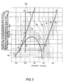
- gaseous phase refrigerant is compressed by the compressor 1 (A - B) into high-temperature, high-pressure refrigerant which then is cooled by the gas cooler 2 (B - C), is throttled and expanded by the expansion device 3 (C - D) into low-temperature, low-pressure refrigerant which then is evaporated by the evaporator 4 (D - A).
- the refrigerant changes into a two-phase gas-liquid state, and when evaporated in the evaporator 4, cools air in the vehicle compartment by depriving the air of latent heat of vaporization.
- the internal heat exchanger 6 in Fig. 3 has a high-pressure passage 12 in a body 11 for high-pressure refrigerant from the gas cooler 2, and a low-pressure passage for low-pressure refrigerant from the accumulator 5.
- the expansion device 3 is disposed in a mounting hole 13 at the end of the high pressure passage 12.
- a pipe 14 communicating with the evaporator 14 is fitted with locking screws 10 to an open end of the mounting hole 13.
- the pipe 14 inner diameter is slightly smaller than the outer diameter of a body 21 of the expansion device 3.
- a central portion of the body 21 has a circumferentially refrigerant-introducing groove 22 which is open to the high-pressure passage 12, and is formed with a refrigerant inlet 23 extending toward the centre of the body 21.
- An axially formed valve hole 24 communicating with the refrigerant inlet 23 is provided in the centre of a lower portion of the body 21.
- a movable valve element 25 is disposed downstream of the valve hole 24.
- the valve element 25 outer diameter is larger than the valve hole 24 inner diameter.
- the pressure from the refrigerant inlet 23 acts in valve-opening direction.
- the valve element 24 is urged in valve-opening direction by a shape-memory alloy spring 26 forming a temperature-sensing section.
- the spring load may be adjusted by axially adjusting the relative position of a spring-receiving member 27 externally fixedly fitted on the valve element 25.
- An orifice 28 in the body 21 bypasses the valve hole 24.
- the body 21 axially movably holds a shaft 29 the lower end of which extends through the valve hole 24 and is rigidly press-fitted into the valve element 25.
- An upper shaft end has a large-diameter engaging portion sitting on a spring-receiving member 30 of a spring 31 urging the shaft 29 and the valve element 25 in valve-closing direction.
- the expansion device 3 is a differential pressure control valve which opens and closes by the differential pressure between the pressures upstream and downstream of the valve hole 24.
- the load of the spring 31 is set such as to yield to open the differential pressure control valve when the inlet side pressure exceeds an upper limit of a control range of the spring load, e.g. 13 MPa.
- the spring load may be adjusted by the amount of press-fitting the shaft 29 into the valve element 25.
- a feature of the shape-memory alloy spring 26 is that the spring load is reversibly changed with respect to the cycle of the temperature, i.e. that the spring load is small at temperatures lower than the transformation temperature and becomes larger in proportion to a change in temperature at temperatures higher than the transformation temperature (transformation between austenitic/martensitic phases of the alloy). Therefore, the shape-memory alloy spring 26 serves as a temperature-sensing actuator or a low temperature-side temperature-sensing section generating a spring load corresponding to the refrigerant temperature on the low-pressure side to control the pressure on the high-pressure side.
- An 0-ring 32 seals between the high-pressure passage 12 and the pipe 14.
- an O-ring 33 between the body 11 and the pipe 14 seals between the low-pressure side and the atmosphere.
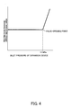
- the expansion device 3 has a fixed restriction passage cross-sectional area determined by the orifice 28.
- the force of the spring 31 in valve-closing direction is overcome.
- the valve element 25 is lifted.
- the valve hole 24 has a sufficiently larger diameter than the orifice 28.
- the shape-memory alloy spring 26 senses the expansion device outlet temperature. When the outlet temperature is high, the shape-memory alloy spring 26 acts in valve-opening direction, but when the outlet temperature is low the spring 26 acts in valve-closing direction. More specifically, when the outlet temperature of the refrigerant is higher than the martensitic/transformation temperature of the shape-memory alloy, the alloy is changed into an austenite or austenitic phase meaning that the spring load largely changes corresponding with temperature. Then the spring load in valve opening direction on valve element 25 changes according to changes in the outlet temperature.
- the outlet temperature is 10°C (see Fig. 2)
- the low pressure side-pressure is approximately 4.6 MPa.
- the shape-memory alloy spring 26 generates a spring load corresponding to this pressure when the temperature is 10°C.
- the differential pressure control valve opens at a differential pressure of 8.4 MPa.
- the inlet pressure is specifically set to be 13 MPa, which is obtained by adding 8.4 MP (the differential pressure as a relative value with respect to 4.6 MPa, which corresponds to the outlet temperature) to 4.6 MPa.
- pressure in the refrigeration cycle changes in the order of A - B - C - D - A.
- the expansion device 3 senses the differential pressure and the outlet temperature, and performs a temperature-dependent correction of the differential pressure by adding the differential pressure to a pressure corresponding to the outlet temperature, i.e. the expansion device 3 operates as if the inlet pressure is controlled by absolute pressure.
- the differential pressure control valve serves simply as a suddenly opening pressure relief valve to maintain the inlet pressure at 13 MPa, preventing an abnormal inlet pressure rise.
- the expansion device 3a (second embodiment in Fig. 5) senses the inlet temperature such that the refrigeration cycle can be operated more efficiently.
- the body 21 has an upper portion with a one piece tubular cylinder accommodating the spring 31 that is deformed by the inlet pressure tending to exceed 13 MPa and opening the differential pressure control valve, and a shape-memory alloy spring 41 for sensing the inlet temperature.
- the springs 31, 41 are arranged in series with a spring receiving member 43 in-between.
- a biasing spring 42 for adjusting the characteristic of the shape-memory alloy spring 41 is arranged parallel with the shape-memory alloy spring 41.
- the spring 31 is disposed between the spring-receiving member 43 through which the shaft 29 loosely extends and the bottom of the tubular cylinder.
- An upward motion of the spring-receiving member 43 is restricted by an adjustment member 44 press-fitted into the cylinder, and a downward motion is restricted by a stopper 45 rigidly fixed to the shaft 29.
- the adjustment member 44 is press-fitted into the cylinder until it reaches a position where it is brought into abutment with the spring 31 which is fully extended to a no spring-load status. Even when a force of the inlet pressure in the valve-opening direction acts via the shaft 29 on the spring 31, the shape-memory alloy spring 41 and the biasing spring 42, the spring 31 is not deformed as long as the inlet pressure is not higher than 13 Mpa. First, and when the inlet pressure exceeds 13 MPa, the spring 31 will yield to quickly open the differential pressure control valve.
- the shape-memory alloy spring 41 senses the inlet temperature.
- the shape-memory alloy spring 41 has a small spring load, and therefore the synthetic load of the shape-memory alloy spring 41 and the spring 42 is small, and the differential pressure for opening the differential pressure control valve is set to a small value.
- the synthetic load of the shape-memory alloy spring 41 and the spring 42 becomes larger, and hence the differential pressure for opening the valve is set to a larger value, i.e.
- the shape-memory alloy spring 41 is in a stiffened state between the spring-receiving member 30 and the spring-receiving member 43 when the inlet temperature is not lower than a predetermined temperature at which a change in the spring load of the shape-memory alloy spring 41 with respect to a change in the temperature is saturated.
- the differential pressure control valve opens by the differential pressure to a very small opening degree just corresponding to the orifice 28. Refrigerant is allowed to flow, causing adiabatic expansion. At this time, the inlet pressure is controlled to a pressure determined by the differential pressure across the differential pressure control valve and a pressure corresponding to the outlet temperature.
- the inlet temperature is sensed by the shape-memory alloy spring 41 so as to shift a predetermined value of the differential pressure subjected to temperature-dependent correction by the shape-memory alloy spring 26, according to a change in the inlet temperature.
- This makes it possible to control the temperature and the pressure at the inlet, that is, a temperature and a pressure at point C in Fig. 2, along a control line CL approximated to an optimal control line that is considered to be capable of enhancing the cooling power while maintaining a high performance coefficient of the refrigeration cycle.
- the expansion device 3b (third embodiment in Fig. 6) differs from the second embodiment in that the positional relationship between the spring 31, the shape-memory alloy spring 41, and the spring 42 is reversed.
- the shape-memory alloy spring 41 When the inlet temperature is low, the shape-memory alloy spring 41 has a small spring load. A valve-opening force generated on the valve element 25 by the differential pressure is transmitted via the shaft 29, the spring-receiving member 30, the spring 31, and the spring-receiving member 43, to bend the shape-memory alloy spring 41.
- the differential pressure control valve opens to a very small opening degree. At this time the inlet pressure is controlled to a pressure corresponding to the differential pressure across the differential pressure control valve and the outlet temperature. Further, the inlet temperature is controlled by the shape-memory alloy spring 41 along the control line CL approximated to the optimal control line.
- the spring 31 senses that the pressure tends exceed 13 MPa, the differential pressure control valve will be suddenly opened.
- the expansion device 3c in Fig. 7 has the same basic construction as the second embodiment, the expansion device 3c differs in that the spring 31, the shape-memory alloy spring 41, and the spring 42 can be assembled and adjusted more easily.
- the spring-receiving member 43 penetrated by the shaft 29 is integral with a hollow cylindrical body accommodating the shape-memory alloy spring 41 and the spring 42.
- a stopper 45 for adjusting both spring loads via the spring-receiving member 30 is press-fitted into the hollow cylindrical body.
- the spring-receiving member 43 is placed on an upper portion of the spring 31.
- the adjustment member 44 is rigidly fixed to the body 21 and accommodates the spring 31 and the spring-receiving member 43.
- the shape-memory alloy spring 41 and the spring 42 are assembled while adjusting their spring loads in advance.
- the shape-memory alloy spring 41 and the spring 42, and the spring-receiving member 30 are placed in the hollow cylindrical body of the spring receiving member 43 in the mentioned order.
- the stopper 45 is press-fitted into the hollow cylindrical body until it reaches a predetermined position, to adjust both spring loads and to complete a high temperature-side temperature-sensing section.
- This high temperature-side temperature-sensing section is placed on the spring 31 disposed in an upper space of the body 21.
- the hollow cylindrical adjustment member 44 having an upper inwardly bent portion is put on from above until an upper portion of the body 21 is partially press-fitted into a lower portion of the adjustment member 44.
- the adjustment member 44 then is further pushed down until the bent portion abuts at an upper end of the spring-receiving member 43,. Then, the adjustment member 44 is fitted to the body 21.
- the spring load of the spring 31 may be adjusted as desired.
- the shaft 29 is inserted from above and is press-fitted by a predetermined amount into the valve element 25 to which is applied the adjusted spring load of the shape-memory alloy spring 26, such that the differential pressure control valve is made open to a predetermined minimum opening degree by the shape-memory alloy spring 26.
- the expansion device 3d in Fig. 8 differs from the fourth embodiment in that in place of the high temperature-side temperature-sensing section a single spring 42a is provided for opening the differential pressure control valve by a differential pressure lower than 13 MPa.
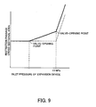
- the expansion device 3d is characterized in that it has (Fig. 9) two valve-opening points at which the differential pressure control valve opens in response to changes in the inlet pressure on the upstream side.
- the expansion device 3d opens to the predetermined minimum opening degree, and then has a fixed restriction passage cross-sectional area.
- the inlet pressure becomes higher, and first exceeds a predetermined value set by the spring 42a, the spring 42a will yield and the differential pressure control valve opens.
- the restriction passage cross-sectional area then increases proportionally.
- the differential pressure control valve suddenly opens to prevent the inlet pressure from rising above 13 MPa.
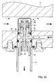
- the expansion device 3e in Fig. 10 has the construction of the second embodiment, the expansion device 3e has a high temperature-side temperature-sensing section for sensing the internal heat exchanger inlet temperature that is, the temperature at the outlet of the gas cooler 2.
- a refrigerant inlet passage 46 into which high-pressure refrigerant is introduced from the gas cooler 2 is formed in the high-pressure passage 12 in the body 11 of the internal heat exchanger 6 such that it passes in the vicinity of the mounting hole 13 for the expansion device 3e.
- the mounting hole 13 extends to the refrigerant inlet passage 46 such that the high temperature-side temperature-sensing section is located within the refrigerant inlet passage 46.
- An O-ring 47 on the periphery of the body 21 prevents leakage between the refrigerant inlet passage 46 and the refrigerant inlet 23.
- the operation is similar to the expansion device 3a but the high temperature-side temperature-sensing section senses the refrigerant temperature at the gas cooler outlet in the internal heat exchanger inlet passage 46.
- the expansion device 3f in Fig. 11 differs from the sixth embodiment by a simpler construction of the high temperature-side temperature-sensing section.
- the stopper 45 in the high temperature-side temperature-sensing section of the expansion device 3e is eliminated, but the shape-memory alloy spring 41 and the spring 42 are arranged in series with the spring 31 for sensing high pressure.
- the shape-memory alloy spring 41 acts in the direction of increasing the spring load of the high pressure-sensing spring 31, and hence the expansion device 3f has the characteristic that it opens the differential pressure control valve in response to changes in the inlet pressure at a valve-opening point not sharply but more smoothly.
- the expansion device 3g in Fig. 12 differs from the first embodiment in that the spring 31 is disposed on the downstream side.
- the valve element 25 is disposed downstream of the valve hole 24 in the body 21.
- the high pressure-sensing spring 31 urges the movable piston 51 integral with the valve element 25 in valve-closing direction.
- the shape-memory alloy spring 26 of the low temperature-side temperature-sensing section urges the piston 51 in valve-opening direction.
- the load of the spring 31 is adjusted by an adjustment screw 52.
- the spring 31 yields in response to the differential pressure between the upstream and downstream pressures, whereby a predetermined value of the differential pressure, required for opening the differential pressure control valve, is subjected to correction dependent on the downstream side outlet temperature as sensed by the shape-memory alloy spring 26, whereby when the upstream side pressure is high, the inlet pressure is always held at 13 MPa as set by the spring 31.
- the orifice 28 is formed in the valve element 25 and allows a minimum flow rate when the differential pressure control valve is fully closed.
- a strainer 53 is disposed upstream of the valve hole.
- the expansion device 3h in Fig. 13 has incorporated a "second" differential pressure control valve in the "first" differential pressure control valve.
- the two differential pressure control valves have different valve-opening points and function in parallel.
- the orifice 28 in the valve element 25 of the first differential pressure control valve is a valve hole of the second differential pressure control valve.
- a valve element 61 disposed on the downstream side co-acts with the valve hole.
- a piston 62 integral with the valve element is axially movably accommodated in the piston 51 of the first differential pressure control valve.
- the piston 62 is urged by the spring 63 in valve-closing direction.
- the spring load of the spring 63 is adjusted by an adjustment screw 64 in the piston 51.
- a bypassing orifice 65 is provided which allows a minimum flow rate when the first and second differential pressure control valves are fully closed.
- the expansion device 3h has the characteristic shown in Fig. 9, i.e. has two valve-opening points at which the expansion device 3h opens in response to changes in the upstream side inlet pressure.
- the shape-memory alloy spring 26 senses the downstream side outlet temperature to correct the predetermined value of differential pressure required for opening the first differential pressure control valve, whereby the inlet pressure is sensed as a pseudo absolute pressure.
- the expansion device 3h has a fixed restriction passage cross-sectional area determined by the cross-sectional area of the orifice 65 of the second differential pressure control valve.
- the second differential pressure control valve opens, and as the differential pressure increases further, the restriction passage cross-sectional area also increases proportionally.
- the first differential pressure control valve starts to open.
- the inlet pressure tends to exceed 13 MPa set by the spring 31
- the first differential pressure control valve suddenly opens. This causes the inlet pressure to decrease, and prevents an increase above 13 MPa.
- the low temperature-side temperature-sensing section corrects the predetermined value of the valve-opening differential pressure for opening the differential pressure control valve according to changes in the downstream side temperature of the differential pressure control valve.
- the predetermined value of the valve-opening differential pressure can be corrected not only according to changes in the downstream side temperature but also according to changes in the downstream side pressure of the differential pressure control valve. This is because the refrigerant at the outlet of the expansion device is in a saturated liquid state, meaning that the temperature and the pressure of refrigerant are constant without undergoing any change, as shown by line D-A or D'-A' of the FIG. 2 Mollier chart. Therefore, if the temperature is also determined, the pressure is determined.
- the evaporation pressure of refrigerant is constant, and moreover between the temperature and the pressure a linear relation holds, so that it is possible to consider that sensing the outlet pressure is equivalent to sensing the temperature at the outlet of the expansion device.
- This allows to provide an expansion device with the same function as in the first to ninth embodiments by replacing the low temperature-side temperature-sensing section by a low temperature-side pressure-sensing section which senses the pressure at the outlet of the expansion device, to correct the predetermined value of the valve-opening differential pressure according to changes in the downstream side pressure of the differential pressure control valve.
- expansion devices with such a low temperature-side pressure-sensing section will be explained.
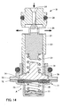
- the expansion device 3i in Fig. 14 has a low temperature-side pressure-sensing section (in place of the shape-memory alloy spring 26 as the low temperature-side temperature-sensing section of the expansion device 3g according to the eighth embodiment).
- a power element 71 is fixed in a hollow cylindrical portion of the body 21. When high pressure is sensed, the power element 71 acts in the direction of decreasing the spring load of the high pressure-sensing spring 31 which sets the valve-opening differential pressure for opening the differential pressure control valve, to thereby serve as a pressure-sensing actuator that corrects a predetermined value of the valve-opening differential pressure in a decreasing direction.
- the power element 71 contains a diaphragm 74 (e.g. a thin metal plate) between an outer housing 72 having a centre projected outward and an inner housing 73 having a central opening and a hub connected to the body 21.
- the outer peripheries of the housings 72 and 73 and the diaphragm 74 are welded together either under high-pressure gas or in a vacuum atmosphere.
- a hermetically sealed space between the outer housing 72 and the diaphragm 74 accommodates a disc spring 75, a spring 76, and a spring receiving member 77.
- the load of the disc spring 75 is adjusted by combining a plurality of disc springs (three in the illustrated example) having respective appropriate spring loads.
- the spring load of the spring 76 is adjusted by plastically inwardly deforming an end face of the outer housing 72 to change the position of the spring-receiving member 77 in the direction of compressing the spring 76.
- a displacement-transmitting member 78 is disposed for transmitting the displacement of the diaphragm 74 to the spring 31.
- a step-shaped stopper 79 is formed on an inner wall of the housing 73 and restricts the motion of the displacement-transmitting member 78 in the direction of increasing the spring load of the spring 31. This inhibits the expansion device from correcting the predetermined value of the differential pressure when the compressor 1 is operating in a state in which the pressure of refrigerant on the downstream side of the differential pressure control valve is low.
- the cut-off part may be dispensed with as the threaded connection does not completely seal.
- the expansion device 3i has a fixed restriction passage cross-sectional area determined by orifice 28.
- the differential pressure control valve overcomes the urging closing force of the spring 31 and opens.
- the valve hole 24 has a sufficiently larger diameter than the orifice 28. Therefore, when the inlet pressure exceeds the set valve-opening point, the restriction passage cross-sectional area of the expansion device 3i suddenly increases. This sudden increase causes the inlet pressure to always remain not higher than corresponding with the valve-opening point.
- the power element 71 on the low-pressure side of the differential pressure control valve senses the outlet pressure of the expansion device 3i.
- the shape of a central portion of the disc spring 75 that receives the pressure via the diaphragm 74 is changed to become concave inward (downward, as viewed in Fig. 14) such that the disc spring 75 acts in the direction of decreasing the valve-opening differential pressure.
- the shape of the central portion of the disc spring 75 is inflated outward (upward, as viewed in Fig. 14) such that the disc spring 75 acts in the direction of increasing the valve-opening differential pressure. That is, the power element 71 corrects the predetermined value of the valve-opening differential pressure, by applying load to the valve element 25 in valve-opening direction corresponding to the outlet pressure of the differential pressure control valve.
- the expansion device 3i senses the differential pressure, and the outlet pressure, and pressure correction is performed by adding the differential pressure to the outlet pressure.
- the expansion device 3i the operates as if it controlled the inlet pressure by absolute pressure.
- the differential pressure control valve suddenly opens, serving simply as a pressure relief valve, so that the inlet pressure is controlled to be held at 13 MPa.
- the power element 71 can detect the outlet pressure of the expansion device 3i as an absolute value, and therefore it is possible to accurately monitor the inlet pressure of the expansion device 3i by the absolute pressure.
- the chamber accommodating the disc spring 75 is charged with a high-pressure gas, it is possible to employ a disc spring 75 having a small spring load only since the high-pressure gas charge acts as an additional air spring.
- the stopper 79 restricts the motion of the displacement-transmitting member 78 such that when the expansion device 3i is separately placed as a part, the high-pressure gas does not inflate the diaphragm 74 excessively toward the differential pressure control valve.
- the shape-memory alloy spring 26 of Fig. 13 is changed to the low temperature-side temperature-sensing section shown in Fig. 14. More specifically, in the expansion device 3j, the power element 71, which when sensing a high pressure, corrects the spring load of the spring 35 urging the first differential pressure control valve in valve-closing direction, in decreasing direction, is screwed into the hollow cylindrical portion of the body 21. Further, the orifice 28 of the valve element 25 of the first differential pressure control valve is provided with the lateral orifice 65 which allows a minimum flow rate even when the first and second differential pressure control valves are fully closed.
- the power element 71 senses the downstream side outlet pressure to correct the predetermined value of the differential pressure required for opening the first differential pressure control valve, whereby the inlet pressure is sensed as a pseudo absolute pressure.
- the expansion device 3j has a fixed restriction passage cross-sectional area determined by the orifice 65 of the second differential pressure control valve.
Landscapes
- Engineering & Computer Science (AREA)
- Physics & Mathematics (AREA)
- Mechanical Engineering (AREA)
- Thermal Sciences (AREA)
- General Engineering & Computer Science (AREA)
- Fluid Mechanics (AREA)
- Temperature-Responsive Valves (AREA)
- Air-Conditioning For Vehicles (AREA)
Applications Claiming Priority (2)
| Application Number | Priority Date | Filing Date | Title |
|---|---|---|---|
| JP2006029557 | 2006-02-07 | ||
| JP2006254254A JP2007240138A (ja) | 2006-02-07 | 2006-09-20 | 膨張装置 |
Publications (1)
| Publication Number | Publication Date |
|---|---|
| EP1816417A2 true EP1816417A2 (fr) | 2007-08-08 |
Family
ID=38117056
Family Applications (1)
| Application Number | Title | Priority Date | Filing Date |
|---|---|---|---|
| EP07002526A Withdrawn EP1816417A2 (fr) | 2006-02-07 | 2007-02-06 | Dispositif d'expansion |
Country Status (3)
| Country | Link |
|---|---|
| US (1) | US20070180854A1 (fr) |
| EP (1) | EP1816417A2 (fr) |
| JP (1) | JP2007240138A (fr) |
Cited By (2)
| Publication number | Priority date | Publication date | Assignee | Title |
|---|---|---|---|---|
| CN102102923A (zh) * | 2009-12-22 | 2011-06-22 | 株式会社不二工机 | 膨胀阀 |
| WO2012072076A3 (fr) * | 2010-11-30 | 2012-11-01 | Danfoss A/S | Soupape de détente à degré d'ouverture variable |
Families Citing this family (4)
| Publication number | Priority date | Publication date | Assignee | Title |
|---|---|---|---|---|
| US20080202156A1 (en) * | 2007-02-26 | 2008-08-28 | Youngkee Baek | Air-conditioning system for vehicles |
| JP5209412B2 (ja) * | 2008-08-22 | 2013-06-12 | サンデン株式会社 | 蒸気圧縮式冷凍サイクル |
| JP5338611B2 (ja) * | 2009-10-19 | 2013-11-13 | 株式会社大林組 | 上下免震装置 |
| US12202319B2 (en) | 2022-06-15 | 2025-01-21 | Ford Global Technologies, Llc | System and method for refrigerant pressure and relief |
Family Cites Families (3)
| Publication number | Priority date | Publication date | Assignee | Title |
|---|---|---|---|---|
| JPH08320171A (ja) * | 1995-05-25 | 1996-12-03 | Fuji Koki Seisakusho:Kk | 開閉弁及びそれを用いた冷凍システム |
| JP2000241048A (ja) * | 1999-02-24 | 2000-09-08 | Saginomiya Seisakusho Inc | 感温膨張弁 |
| JP2001153499A (ja) * | 1999-11-30 | 2001-06-08 | Saginomiya Seisakusho Inc | 冷凍サイクル用制御弁 |
-
2006
- 2006-09-20 JP JP2006254254A patent/JP2007240138A/ja active Pending
-
2007
- 2007-02-02 US US11/701,497 patent/US20070180854A1/en not_active Abandoned
- 2007-02-06 EP EP07002526A patent/EP1816417A2/fr not_active Withdrawn
Cited By (4)
| Publication number | Priority date | Publication date | Assignee | Title |
|---|---|---|---|---|
| CN102102923A (zh) * | 2009-12-22 | 2011-06-22 | 株式会社不二工机 | 膨胀阀 |
| WO2012072076A3 (fr) * | 2010-11-30 | 2012-11-01 | Danfoss A/S | Soupape de détente à degré d'ouverture variable |
| CN103339453A (zh) * | 2010-11-30 | 2013-10-02 | 丹佛斯公司 | 具有可变开度的膨胀阀 |
| US9170039B2 (en) | 2010-11-30 | 2015-10-27 | Danfoss A/S | Expansion valve with variable opening degree |
Also Published As
| Publication number | Publication date |
|---|---|
| US20070180854A1 (en) | 2007-08-09 |
| JP2007240138A (ja) | 2007-09-20 |
Similar Documents
| Publication | Publication Date | Title |
|---|---|---|
| EP1892488A2 (fr) | Dispositif détendeur | |
| US20070209387A1 (en) | Expansion valve | |
| US20070180854A1 (en) | Expansion device | |
| US20080011363A1 (en) | Pressure Control Valve | |
| JP2010112616A (ja) | 温度式膨張弁 | |
| EP1659352A2 (fr) | Dispositif d'expansion | |
| EP3385645B1 (fr) | Climatiseur | |
| US20080127664A1 (en) | Thermostatic expansion valve for refrigeration or heat-pump circuits with thermally controlled safely function | |
| JPH10288411A (ja) | 蒸気圧縮式冷凍サイクル | |
| JP2004142701A (ja) | 冷凍サイクル | |
| JP2000241048A (ja) | 感温膨張弁 | |
| EP1785681A1 (fr) | Soupape de commande à haute pression | |
| US20100024453A1 (en) | Refrigeration cycle device | |
| JP2006292184A (ja) | 膨張装置 | |
| JP2008138812A (ja) | 差圧弁 | |
| KR20140076507A (ko) | 제어 밸브 | |
| JP2000186870A (ja) | 冷凍サイクル用制御弁 | |
| JP2009063233A (ja) | 冷凍サイクルの制御方法 | |
| JPH1163739A (ja) | 圧力制御弁 | |
| JP3920059B2 (ja) | 膨張弁 | |
| JP2007278616A (ja) | 膨張装置 | |
| JP2009008369A (ja) | 冷凍サイクル | |
| JP2007033021A (ja) | 温度差圧感知弁 | |
| JP2007024486A (ja) | 膨張装置 | |
| JP2007046808A (ja) | 膨張装置 |
Legal Events
| Date | Code | Title | Description |
|---|---|---|---|
| PUAI | Public reference made under article 153(3) epc to a published international application that has entered the european phase |
Free format text: ORIGINAL CODE: 0009012 |
|
| AK | Designated contracting states |
Kind code of ref document: A2 Designated state(s): AT BE BG CH CY CZ DE DK EE ES FI FR GB GR HU IE IS IT LI LT LU LV MC NL PL PT RO SE SI SK TR |
|
| AX | Request for extension of the european patent |
Extension state: AL BA HR MK YU |
|
| STAA | Information on the status of an ep patent application or granted ep patent |
Free format text: STATUS: THE APPLICATION HAS BEEN WITHDRAWN |
|
| 18W | Application withdrawn |
Effective date: 20081202 |