EP1817128B1 - Element de coupe, support de lames et meche creuse - Google Patents
Element de coupe, support de lames et meche creuse Download PDFInfo
- Publication number
- EP1817128B1 EP1817128B1 EP05818386A EP05818386A EP1817128B1 EP 1817128 B1 EP1817128 B1 EP 1817128B1 EP 05818386 A EP05818386 A EP 05818386A EP 05818386 A EP05818386 A EP 05818386A EP 1817128 B1 EP1817128 B1 EP 1817128B1
- Authority
- EP
- European Patent Office
- Prior art keywords
- cutting element
- cutting
- cutter support
- element according
- region
- Prior art date
- Legal status (The legal status is an assumption and is not a legal conclusion. Google has not performed a legal analysis and makes no representation as to the accuracy of the status listed.)
- Expired - Lifetime
Links
Images







Classifications
-
- B—PERFORMING OPERATIONS; TRANSPORTING
- B23—MACHINE TOOLS; METAL-WORKING NOT OTHERWISE PROVIDED FOR
- B23B—TURNING; BORING
- B23B51/00—Tools for drilling machines
- B23B51/04—Drills for trepanning
-
- B—PERFORMING OPERATIONS; TRANSPORTING
- B26—HAND CUTTING TOOLS; CUTTING; SEVERING
- B26F—PERFORATING; PUNCHING; CUTTING-OUT; STAMPING-OUT; SEVERING BY MEANS OTHER THAN CUTTING
- B26F1/00—Perforating; Punching; Cutting-out; Stamping-out; Apparatus therefor
- B26F1/16—Perforating by tool or tools of the drill type
-
- B—PERFORMING OPERATIONS; TRANSPORTING
- B23—MACHINE TOOLS; METAL-WORKING NOT OTHERWISE PROVIDED FOR
- B23B—TURNING; BORING
- B23B2226/00—Materials of tools or workpieces not comprising a metal
- B23B2226/33—Elastomers, e.g. rubber
-
- B—PERFORMING OPERATIONS; TRANSPORTING
- B23—MACHINE TOOLS; METAL-WORKING NOT OTHERWISE PROVIDED FOR
- B23B—TURNING; BORING
- B23B2226/00—Materials of tools or workpieces not comprising a metal
- B23B2226/39—Foam
-
- B—PERFORMING OPERATIONS; TRANSPORTING
- B23—MACHINE TOOLS; METAL-WORKING NOT OTHERWISE PROVIDED FOR
- B23B—TURNING; BORING
- B23B2226/00—Materials of tools or workpieces not comprising a metal
- B23B2226/61—Plastics not otherwise provided for, e.g. nylon
-
- B—PERFORMING OPERATIONS; TRANSPORTING
- B23—MACHINE TOOLS; METAL-WORKING NOT OTHERWISE PROVIDED FOR
- B23B—TURNING; BORING
- B23B2228/00—Properties of materials of tools or workpieces, materials of tools or workpieces applied in a specific manner
- B23B2228/28—Soft
-
- B—PERFORMING OPERATIONS; TRANSPORTING
- B23—MACHINE TOOLS; METAL-WORKING NOT OTHERWISE PROVIDED FOR
- B23B—TURNING; BORING
- B23B2240/00—Details of connections of tools or workpieces
- B23B2240/08—Brazed connections
-
- B—PERFORMING OPERATIONS; TRANSPORTING
- B23—MACHINE TOOLS; METAL-WORKING NOT OTHERWISE PROVIDED FOR
- B23B—TURNING; BORING
- B23B2240/00—Details of connections of tools or workpieces
- B23B2240/16—Welded connections
-
- B—PERFORMING OPERATIONS; TRANSPORTING
- B23—MACHINE TOOLS; METAL-WORKING NOT OTHERWISE PROVIDED FOR
- B23B—TURNING; BORING
- B23B2240/00—Details of connections of tools or workpieces
- B23B2240/21—Glued connections
-
- B—PERFORMING OPERATIONS; TRANSPORTING
- B23—MACHINE TOOLS; METAL-WORKING NOT OTHERWISE PROVIDED FOR
- B23B—TURNING; BORING
- B23B2250/00—Compensating adverse effects during turning, boring or drilling
- B23B2250/12—Cooling and lubrication
-
- B—PERFORMING OPERATIONS; TRANSPORTING
- B23—MACHINE TOOLS; METAL-WORKING NOT OTHERWISE PROVIDED FOR
- B23B—TURNING; BORING
- B23B2251/00—Details of tools for drilling machines
- B23B2251/02—Connections between shanks and removable cutting heads
-
- Y—GENERAL TAGGING OF NEW TECHNOLOGICAL DEVELOPMENTS; GENERAL TAGGING OF CROSS-SECTIONAL TECHNOLOGIES SPANNING OVER SEVERAL SECTIONS OF THE IPC; TECHNICAL SUBJECTS COVERED BY FORMER USPC CROSS-REFERENCE ART COLLECTIONS [XRACs] AND DIGESTS
- Y10—TECHNICAL SUBJECTS COVERED BY FORMER USPC
- Y10T—TECHNICAL SUBJECTS COVERED BY FORMER US CLASSIFICATION
- Y10T408/00—Cutting by use of rotating axially moving tool
- Y10T408/89—Tool or Tool with support
- Y10T408/895—Having axial, core-receiving central portion
-
- Y—GENERAL TAGGING OF NEW TECHNOLOGICAL DEVELOPMENTS; GENERAL TAGGING OF CROSS-SECTIONAL TECHNOLOGIES SPANNING OVER SEVERAL SECTIONS OF THE IPC; TECHNICAL SUBJECTS COVERED BY FORMER USPC CROSS-REFERENCE ART COLLECTIONS [XRACs] AND DIGESTS
- Y10—TECHNICAL SUBJECTS COVERED BY FORMER USPC
- Y10T—TECHNICAL SUBJECTS COVERED BY FORMER US CLASSIFICATION
- Y10T408/00—Cutting by use of rotating axially moving tool
- Y10T408/94—Tool-support
- Y10T408/95—Tool-support with tool-retaining means
Definitions
- the invention relates to a cutting element according to the preamble of claim 1 and a blade carrier for a hollow drill according to the preamble of claim 17. Furthermore, the invention relates to a hollow drill according to claim 22.
- Cutting elements, blade carriers and hollow drill of the type mentioned here are used in particular for producing holes in layers of thin sheet material such as paper, cardboard, plastic film, rubber, etc. or soft, resilient materials such as foam and polystyrene.
- a hollow drill is usually driven in rotation and cuts out the cuttings with a cutting element substantially circular.
- the hollow drill can also be used without additional rotary drive, wherein a punching of the cuttings takes place by means of the cutting element.
- the cut out cuttings are typically discharged through a drill sleeve or a pipe to the outside.
- the drill sleeve is also referred to below as a blade carrier.
- Cutting elements, blade carriers and hollow drills can also be summarized under the term drilling tools.
- Hollow drills are largely made of one piece of tool steel. The production takes place by cutting solid material.
- Hollow drill in which cutting element and blade carrier are designed as separate components, are already known. So is in the utility model DE 7005824 U1 a paper drill described in which the tube of the paper drill on the cutting side a cutting element forming hard metal crown is soldered. The joint between pipe and carbide crown is designed to fit one another conical. In this way, the soldering surface is considerably increased and the cone takes over a large part of the forces occurring.
- a cutting element which is attached to a separately manufactured pipe.
- the tube may be made of the same material as the cutting element or of another material.
- the tube can also be made by a different manufacturing process than the cutting element. The use of different manufacturing methods for the tube and the cutting element leads to a hollow drill with good mechanical properties.
- the cutting element is conical and has on its outside convex indentations.
- JP 11156617 A is a diamond-coated hollow drill is known in which the annular end in the axial direction is convex and concave.
- the hollow drill is operated in rotation.
- the concave and convex shapes serve to suppress vibrations during use of the hollow drill.
- the object of the invention is to provide a cutting element, a blade carrier and a hollow drill, which can be used efficiently for drilling.
- the cutting element is also referred to as drill bit or cutting edge.
- the blade carrier is also referred to as pipe support or pipe. The list of terms is not exhaustive.
- the cutting element according to the invention comprises a cutting region and a substantially cylindrical region and is characterized in that the essentially cylindrical region has indentations which are arranged on the inside at preferably regular intervals and open in the direction of the cutting region. This allows efficient use of the cutting element during drilling.
- the depressions can also be referred to as cavities.
- the depressions extend in the axial direction, wherein they are preferably arranged in the circumferential direction at a distance from one another.
- regular depressions creates a geometric shape, which is commonly referred to as polygon or polygon.
- the substantially cylindrical area can have a polygonal inner shape, wherein the edges are connected to each other via a respective recess.
- the edges can run straight; but they can also be convex, concave, wavy shaped. In this way results in a low friction on the inside of the cutting element.
- the polygonal inner shape preferably merges conically into a cylindrical inner shape at the side opposite the cutting region of the cutting element.
- the recesses are characterized by a helical course on the inside of the substantially cylindrical region.
- the helical course can also be referred to as a spiral course or as a course in twisted polygons.
- This configuration of the recesses makes it possible to prematurely form the drilling or cutting material at locations defined by the helix in order to reduce the axial pressures occurring during the cutting process.
- the configuration of the depressions leads to a targeted displacement of the contour lines on the inside of the substantially cylindrical region, through which a defined deformation, in particular a defined folding of the cutting material, can be initiated.
- the cutting region of the cutting element also has recesses, which preferably extend helically or spirally.
- Schneidgutverformungen can be effected, which lead to a minimization of the axial pressures occurring.
- a lubricant is incorporated in the substantially cylindrical region of the cutting element. This can be provided in particular in the wells. Particularly preferably, a lubricant is used, which passes into liquid state only when exceeding a certain limit temperature.
- the recesses in the substantially cylindrical portion of the cutting element are designed as cuts.
- tongues are formed in the cylindrical region of the cutting element, which tongues extend in the axial direction, in the opposite direction to the cutting region.
- the cuts are also referred to as slots or tongue slots. They can protrude into the cutting area.
- the tongues are pressed by the material to be cut outwards and thus against the cutter carrier.
- the cuts can also be provided in the cutting element-side region of the cutter carrier, so that the cutter carrier has tongues which extend in the axial direction.
- a permanent connection of cutting element and blade carrier, for example by means of soldering is not required in this embodiment.
- the cutting element designed in this way is replaceable. As soon as the cutting element becomes dull or the material to be cut is changed, the cutting element can advantageously be replaced by a new or different cutting element.
- this interchangeable cutting element it is also possible with this interchangeable cutting element to connect it permanently, for example, by soldering, gluing and / or laser welding to the blade carrier.
- a preferably likewise cylindrical ring is arranged in the substantially cylindrical area.
- the ring is made of steel in particular. But it can also be made of a different material, such as plastic.
- the ring is preferably used in the above-described exchangeable cutting element, to increase the compressive force on the tongues, if the cutting element is used to cut such soft materials (for example, very soft foams), which, taken separately, are too soft to squeeze the tongues outwardly against the blade carrier.
- the blade carrier according to the invention has an opening for the cutting element and is characterized by a conically executed region in which the cone angle opens in the opposite direction to the opening for the cutting element. Furthermore, elevations for receiving the depressions of the cutting element are provided on the inside of the cutter support, which are designed in particular as incisions. The elevations prevent twisting of the cutting element relative to the cutter carrier.
- the conical configuration of the cutter carrier makes it difficult to loosen or pull out the cutting element.
- the cone angle is 1 ° to 6 °, more preferably 1.5 ° to 3 °, wherein the cone angle is defined as the angle between the axis of the blade carrier and the tapered portion of the blade carrier.
- a cylindrical region which preferably has a smaller diameter than the conically shaped region at the point at which it is furthest from the opening for the cutting body, adjoins the conically executed region in the direction opposite to the opening for the cutting element Cutting element is removed. In this way, a connection point is created at the cutter carrier, by which a positive connection with the cutting element can be effected.
- the object is further achieved by a hollow drill according to claim 22.
- the hollow drill according to the invention is characterized by an inventive cutting element and a blade carrier according to the invention, which are designed as separate components.
- Cutting element and blade carrier can be releasably connected to each other via a clamping connection.
- the cutting element can also be connected to the blade carrier via an adhesive, soldering and / or welded connection, in particular by means of laser welding.
- the hollow drill has a shaft on which the hollow drill can be received, for example, by a drilling device, which is designed as a separate component.
- the shank is provided at the end of the blade carrier opposite the cutting element.
- the materials of cutting element, cutter support and shaft are each selected depending on the intended use of the component in question.
- Cutting element, blade carrier and shaft can also be produced by means of various manufacturing processes in such a separate construction. Of course, they can also be produced by the same manufacturing process.
- the separate production of the components cutting element, blade carrier and / or shank creates less material waste.
- additional energy can be saved.
- hardening can be dispensed with in the case of the blade carrier and the shaft.
- the material need not be optimized for as many of the enumerated properties as possible, but for the shank, for example, a material with low hardenability and coatability but low raw material price can be selected, while the cutting element has a material with high hardenability and good coatability but also high price could be chosen.
- the separate production of cutting element, blade carrier and shank can thus lead to a favorable production and long service life of the drilling tools. Coatings of the individual components, in particular the cutting element and / or the cutter carrier also lead to an increase in service life.
- a material is preferably selected, which allows a good clamping of the hollow drill in a spindle.
- a material is preferably selected which has a good fatigue strength.
- the material of the cutting element is selected with regard to an increase in service life or service life.
- these components can also be manufactured from one piece.
- FIG. 1 Representation (a) shows an exploded view of a cutting element 1, which is connected to a cutter support 2, which in turn is connected to a shaft 24.
- Cutting element 1, blade carrier 2 and shaft 24 are preferably components of a hollow drill.
- the cutting element 1 has a preferably conical cutting region 3 and a substantially cylindrical region 4 adjoining the cutting region 3, which preferably-if there is any conicity at all, wherein the bore inclination is preferably 1:50 to 1: 100 in order to move rapidly to allow free running of the cuttings.
- Representation (b) is a plan view of the embodiment shown in illustration (a).
- Diagram (d) shows an assembled perspective drawing of the embodiment shown in illustration (a).
- the internal geometry is configured in this form essentially star-shaped.
- 1 recesses 5 are provided on the inside of the cylindrical portion 4 of the cutting element, which extend in the axial direction and are arranged spaced from each other in the circumferential direction.
- the depressions 5 are connected to each other via a preferably formed as projecting into the cylindrical portion tip 6.
- the elevations 6 are shown as lines.
- the elevations 6 act practically as skids on which the material to be cut or the cuttings can slide along. This leads to a reduction of friction.
- the illustration (c) shows the region enclosed in the illustration (a) by a circle as a detail enlargement. It can be seen that the depressions 5 level out shortly before the side of the cutting element 4 facing away from the cutting region 3, that is, transition into a cylindrical inner shape.
- FIG. 2 shows a further embodiment of a cutting element 1.
- the cutting element 1 is composed of a preferably conical cutting region 3 and a substantially cylindrical portion 4 together.
- the cylindrical region has on the inside in the circumferential direction at a distance, in the direction of the cutting area opening recesses 5.
- the distances between the recesses 5 are preferably the same size.
- the recesses 5 are connected to each other via edges 7, which may be flat, concave, convex or wavy.
- the cylindrical region 4 thus has a polygonal inner shape in a first subregion 4.1.
- This polygonal inner shape is preferably conical in a partial region 4.2 with a cylindrical inner shape. In this transition preferably decreases the diameter of the cylindrical portion 4.
- the entire substantially cylindrical portion 4 may be conical. However, only the portion 4.1 may be conical and the portion 4.2 may have a constant diameter or vice versa.
- the polygonal inner shape and / or the conical shape cause a low coefficient of friction on the inside
- edges 7 lubricant is preferably incorporated, which may be selected such that it only becomes liquid when a certain limit temperature is exceeded.
- FIG. 3 shows a perspective view of another embodiment of a cutting element 1 with a preferably conical cutting area 3 and a subsequent to the cutting area 3 substantially cylindrical portion 4.
- the cylindrical portion 4 has depressions 5, which extend helically on the inside of the region 4. In diesem Fall ist die Ausbloodung 5 mit der Ausnaturalung 5 lbs.
- the recesses 5 may additionally extend at least partially in the axial direction.
- the depressions 5 can be connected to one another in a single helical depression 5.
- the depressions 5 are preferably arranged in a first subregion 4.1 of the cylindrical region 4, to which a second subregion 4. 2 adjoins the end opposite the cutting region 3, which preferably has a cylindrical inner shape.
- the portion 4.1 with the recesses 5 is preferably conical in the cylindrical portion 4.2, wherein the diameter of the portion 4.1 is reduced.
- the sub-area 4.2 can also be made conical.
- the helical configuration of the recesses 5 leads to a corresponding configuration of elevations on the inside of the cylindrical region 4 and in this way to a shift of contour lines on the inside.
- the material to be cut is formed prematurely during a cutting process. This leads to a reduction of the occurring axial pressures.
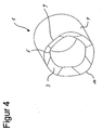
- FIG. 4 shows a further perspective embodiment of a cutting element 1 with a preferably conical cutting region 3 and a substantially cylindrical region 4.
- the illustrated embodiment differs from the embodiments shown in Figures 1 to 3 in particular by the fact that the cutting region has 3 recesses 9.
- the cylindrical region 4 can also be used in particular in the FIGS. 1 to 3 have recesses 5 shown.
- the depressions 9 preferably have a helical course and, when they are arranged adjacent to one another, can form a single helical depression 9.
- elevations 10 are formed, which cause material deformations and thus can minimize axial pressures occurring during cutting.
- This embodiment is particularly suitable for cutting rubber and soft materials.
- FIG. 5 a further embodiment of a cutting region 3 of a cutting element is shown.
- the cutting area 3 has concave depressions 9, between each of which a serrated elevation 10 is arranged.
- This embodiment of Cutting area 3 allows a good penetration of the cutting element in the material to be cut. You can be with the in the FIGS. 1 to 3 combine illustrated embodiments.
- FIG. 6 a further embodiment of a cutting element 1 is shown.
- the cutting element 1 has a preferably conical cutting region 3 and an essentially cylindrical region 4 adjoining the cutting region 3.
- the cylindrical region 4 has recesses, which are formed as cuts or slots 11.
- the slots 11 are preferably open on the outside of the cylindrical portion 4, that is, they extend to the outside of the cutting element 1.
- the cuts 11 are preferably arranged at a distance from each other in the circumferential direction on the inside of the cylindrical portion 4 and preferably extend in axial direction. They are connected to each other via wall segments 12, which are also referred to as tongues.
- the wall segments 12 may have a flat or domed surface.
- the incisions 11 can protrude into the cutting area 3.
- cutting element 1 represents an interchangeable cutting element, which can be fixed without a permanent connection-for example by means of loosening, gluing or welding- in a blade carrier. If the cutting element has become dull or the cutting material is changed, the cutting edge can be replaced by pulling out of the blade carrier.
- the cutting element 1 is pushed into a blade carrier and the tongues 12 are pressed by the material to be cut outwards and thus against the blade carrier.
- the cutting element 1 is held in particular by clamping forces in the blade carrier.
- FIGS. 1 to 6 Illustrated embodiments are possible. So that can be done in FIG. 6 cutting element 1 shown a cutting area 3 according to the FIGS. 4 and 5 exhibit. Likewise, the slots 11 of the FIG. 6 run helically. Additionally or alternatively, the tongues 12 in the sense of in the FIG. 1 illustrated embodiment pointing inward pointed.
- the recesses 5 may also have a helical course and / or be designed as incisions. Additionally or alternatively, the edges 7 may have tips pointing into the interior of the cylindrical area 4. Further combinations are possible.
- FIG. 7 shows a cutter support 2 with an opening 13 for receiving one of the in the FIGS. 1 to 6 illustrated cutting elements.
- the illustrated blade carrier 2 is particularly suitable for receiving a replaceable cutting element 1 FIG. 6 suitable.
- Such a cutting element 1 is in the FIG. 7 shown shortly before insertion in the blade carrier 2.
- FIG. 8 shows a further embodiment of a cutter support 2 and a cutting element 1 in here as a side view (a) designated longitudinal sectional view, partial perspective view (b) and plan view (c).
- the cutting element 1 consists of a cutting region 3 and a substantially cylindrical region 4.
- the substantially cylindrical region 4 preferably has a conical shape on its outside, which leads to an enlargement of the outside diameter in the opposite direction to the cutting region 3.
- the cutter support 2 has a conically executed region 18, in which the cone angle opens in the opposite direction to the opening for the cutting element 1.
- the cone angle is preferably 2 ° to 3 °.
- the outside of the cylindrical region 4 preferably runs at the same angle.
- the outer diameter of the cutting region 3 may correspond to the outer diameter of the cutter carrier 2.
- the cutting area 3 facing the end of the cylindrical portion 4 preferably has an outer diameter which corresponds approximately to the inner diameter of the cutting area side end of the cutter support 2.
- the outer diameter of the cylindrical region 4 on the side opposite the cutting region 3 preferably likewise corresponds approximately to the inner diameter on the end opposite the cutting region 3
- the cylindrical region 4 of the cutting element 1 and the conically executed region 18 of the cutter carrier are approximately the same length.
- a preferably cylindrical region 20, whose diameter is preferably smaller than the outer diameter of the cylindrical region 4 of the cutting element 1, follows.
- the illustrated blade carrier 2 is particularly suitable for receiving a removable blade, as for example in FIG. 6 is shown.
- elevations may be provided on the inside of the conical portion 18 of the cutter support 2, which serve to accommodate the provided between the tongues 12 slots 11.
- a preferably cylindrical ring in particular a steel ring, may be provided within the cylindrical region 4 of the cutting element 1.
- the ring 19 serves to reinforce the pressing force, which is exerted by the material to be cut on the tongues 12 and the cylindrical portion 4.
- the blade carrier 2 shown in side view and plan view preferably has a conical inner coating 21, shown by way of example.
- the diameter of the conical inner coating 21 increases preferably in the opposite direction to the opening 13, which serves to receive a cutting element 1.
- FIGS. 9 (c) and (d) is a blade carrier 2 according to the FIGS. 9 (a) and (b) shown in side view and top view, in which in the inner coating 21, a cutting element 1 is positively inserted.
- the introduction of the cutting element can for example take place in that an adhesive takes on both the role of the inner coating 21, as well as the adaptation of the cutting element 1 is used.
- the holding forces from the cutting element 1 to the inner coating 21, which preferably comprises an adhesive can be increased inter alia by the cutting element 1 having tongues (not shown) which extend in the longitudinal direction and in whose interstices the inner coating 21, preferably comprising an adhesive, intercalates can.
- the choice of the coating material of the inner coating 21 depends basically on the cuttings to be cut.
- the inner coatings are realized by low-melting solder and / or plastic, in particular by means of plastic injection molding, and / or curing adhesives and / or paints.
- materials such as Teflon, titanium nitrite, so-called TiAIN, and / or hard metal coatings or hard coatings are usually used.
- Common cutting materials and hard coatings can be used. Particular preference is given to using diamond coatings and / or coatings based on boron nitride. Preferably, monocrystalline diamond coatings are used.
- the diamond layers can be applied by the detonation coating method.
- the listed materials can also be used for a provided on the inside of the cutting element 3 coating.
- the cutter carrier 2 as in FIGS Figures 10 and 11 represented on its inside preferably a conically shaped joint 22, whose radius increases cutting area side.
- Representation (a) shows a side view
- representation (b) is a plan view of the joint. Accordingly, as out FIG. 11 it can be seen, the cutting element 1 in the substantially cylindrical portion 4 on the outside of a conically narrowing region 4.2, the cone angle of which corresponds to the joint 22.
- the length of the conical region 4.2 of the cutting element preferably corresponds approximately to the length of the joint 22 of the cutter carrier.
- Representation (c) shows the in the Figures 10 and 11 (a) and (b) shown cutter carrier and cutting elements before (left figure) and after (right figure) the assembly.
- the substantially cylindrical portion 4 of the cutting element 1 can, as in the FIGS. 1 to 6 and 8th be shown represented.
- Cutting element 1 and blade carrier 2 can by a self-locking clamping connection; be bonded together by gluing, soldering and / or laser or laser welding. Mixed forms of joining techniques are conceivable. When gluing or soldering 22 adhesive or solder is attached to the joint. For an alternative or additional laser connection, the cutting element 1 and the blade carrier 2 are welded together at a joint line 23, which preferably the cutting area-side end of the blade carrier equivalent. The choice of bonding method depends on the materials used and the costs to be considered. If the connection is made by gluing and laser welding, the material is thrown up and thickened later. When soldering, rework may be required.
- the opening angle that is, the angle between the in-plane side walls of the joint should preferably be less than 60 °. Since the cone angle, that is, the angle between the inner wall and the outer wall of the joint 22 is kept small, advantageously occur self-locking effects, as is the case for example with a Morse taper.
- FIGS. 9 to 11 coating or bonding examples shown also find in the in the FIGS. 6 to 8 illustrated cutting elements 1 and blade carrier 2 application.
- the cutter holders 2 of FIGS. 7 and 8th also be provided coatings.
- the conically flared portion 18 of the FIG. 8 or 16 of the FIG. 7 be provided with adhesive and / or solder to produce a permanent connection in addition to the effect of positive connection or clamping effect connection.
- the blade carrier shown can also be connected by laser welding to the cutting element 1.
- a weld could be applied to the cutting element side end of the conical section 15.
- a weld seam is provided in the transition between the cutting region 3 and the essentially cylindrical region 4, in which the cutting-element-side end of the cone-shaped region 18 of the cutter carrier 2 comes to rest.
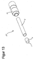
- the Figures 12 and 13 show a hollow drill with a cutting element 1 and a shaft 24, which are connected to each other via a blade carrier 2, in side view (representation 12 (a)) and plan view (representation 12 (b)) and exploded view ( FIG. 13 ).
- the cutting element 1 has a cutting region 3 and a substantially cylindrical region 4.
- the cutting element 1 and the blade carrier 2 can, as in the FIGS. 1 to 11 be shown represented.
- Cutting element 1 and blade carrier 2 are formed as separate parts.
- the shaft 24 is designed as a separate part.
- the exploded view 13 of the hollow drill 25 illustrates the structure of separate components.
- the shaft serves for clamping a hollow drill in a spindle, for example a machine tool.
- the shank 24 is preferably made by turning and / or drawing so-called free-cutting steel. This material is particularly suitable for machining on lathes with high cutting speeds.
- the shaft 24 may be relatively soft, as it merely serves to tension and adapt to different tensioning systems. In addition, it serves to receive the cutter carrier 2.
- the blade carrier 2 is preferably made of so-called VA steel (stainless steel DIN 1.4301), preferably by drawing.
- the material can be additionally finished.
- VA steel is characterized by being rust-proof and corrosion-resistant. Of course, other materials can be used. It can be used for example as a blade carrier 2, a carbon fiber tube. In particular, a material must be used for the blade carrier 2, which ensures a good fatigue strength.
- the cutting element 1 consists of a wear-resistant material, in particular of hardened and coated powder metallurgical material. Alternatively or additionally, hard metals, ceramics and / or diamond coatings can also be used.
- the internal configuration of the cutting element 1 can be optimally matched to the material to be drilled with an additional coating. However, the use of an additional coating is not mandatory.
- the internal embodiments according to the FIGS. 1 to 6 into consideration.
- the connection between the blade carrier 2 and shaft 24 can therefore according to the in the Figures 10 and 11 made connection shown.
- the connection methods described for these figures are also applicable.
- An adhesive bond has the advantage that no heat distortion occurs, it is a cost-effective solution and the compound chemically innert and the strength requirements is met.
- the cone angle of blade carrier 2 and shaft 24 can also be 0 °.
- the hollow drill 25 is usually operated by means of a drill spindle.
- the drill spindle has for this purpose an opening for receiving the shaft.
- the opening may have a special chuck.
- adapters 26 may be provided (see FIG. 14 ), which serve to adapt the shaft circumference to the diameter of the opening of the drill spindle.
- Fig. 14 (a) is a side view
- Fig. 14 (b) is the corresponding plan view.
- the provision of adapter and / or chuck is independent of a multi-piece design of the hollow drill.
- blade carrier 2 and shaft 24 are designed as separate components, instead of an adapter or if no suitable chuck is provided in the drill spindle, the shaft can simply be exchanged for a suitable shaft 24. The separate execution of cutter carrier 2 and shaft 24 thus leads to a flexible drilling tool.
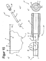
- FIG. 15 shows a further preferred embodiment of a cutting element 1, a blade carrier 2, a shaft 24 and a hollow drill 25 in side view (representation (a)), plan view (representation (b)) and exploded view (representation (d)).
- Representation (c) shows the region enclosed in the representation (a) by a circle as a detail enlargement.
- the cutter carrier 2 on its outside cutting element side on a conically shaped first joining region 30, whose radius decreases in the direction of the cutting element 1.
- the cone angle is preferably 1.5 °. Accordingly, the cutting element 1 on its inner side cutting carrier side on a conically widening joining region 32.
- the cone angle of the joining region 32 of the cutting element 1 is selected according to the cone angle of the first joining region 30 of the cutter carrier 2.
- the axial extent of the first joining region 30 of the cutter carrier 2 preferably corresponds to the axial extent of the joining region 32 of the cutting element 1.
- the inner diameter of the cutting element 1 is preferably smaller than the inner diameter of the cutter carrier 2, so that the cutting material is an optionally forming edge on the Joint 34 can pass unhindered.
- the blade carrier 2 preferably also has on its outer side a conically shaped second joining region 31, the radius of which decreases in the direction of the shaft 24. Accordingly, the shaft 24 on its inner side cutting carrier side on a conically widening joining region 33.
- the cone angle of the joining region 33 of the shaft 24 is selected according to the cone angle of the second joining region 31 of the cutter carrier 2.
- the axial extent of the second joining region 31 of the cutter carrier 2 preferably corresponds to the axial extent of the joining region 32 of the shaft 24.
- the cutter carrier on the inside can have a conically shaped joining region, the radius of which widens in the direction of the shaft, while the shaft on the Outside cutting carrier side a conically narrowing joint area whose cone angle is selected according to the cone angle of the second joining region of the cutter carrier.
- cutting element 1 and blade carrier 2 can be interconnected by a self-locking clamping connection, by gluing, soldering and / or laser or laser welding.
- Mixed forms of joining techniques are conceivable.
- the first joining region 30 of the cutter carrier 2 and the joining region 32 of the cutting element 1 are joined together to form a joint 28.
- the second joining region 31 of the cutter carrier and the joining region 33 of the shaft 24 can be connected to one another to form a joint 29.
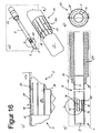
- FIG. 16 By appropriate design of blade carrier and cutting element can in analogy to the particular in FIG. 7 illustrated embodiment also in the in FIG. 15 illustrated embodiment, a so-called click or clip connection between the blade carrier and cutting element or between blade carrier and shaft are created.
- FIG. 16 Such a configuration for a clip connection between cutting element 1 and blade carrier 2 is in FIG. 16 shown. That in the FIG. 16 illustrated embodiment differs from that in the FIG. 15 illustrated embodiment in that 2 axially extending slots 35 are provided in the first joining region 30 of the cutter support. By the slots 35 tongues 36 are formed, which are compressed upon introduction of the joining region 30 of the cutter support 2 in the joining region 32 of the cutting element 1 and thereby cause a clamping connection.
- the joining region 32 of the cutting element 1 is designed so that it one of the slots 35 and the tongues 36 corresponding counter contour has;
- a conically widening region can adjoin an area which conically constricts in the cutting region direction via an apex (not shown), so that the tongues 36 can move outward again in the conically widening region.
- the vertex prevents easy removal of the cutter carrier or of the cutting element.
- the conically widening region of the joining region 32 of the cutting element 1 preferably has slots for receiving the tongues 36 of the cutter carrier 2, so that security against rotation is ensured.
- the second joining region 31 of the cutter carrier and the joining region 33 of the shaft 24 can be designed accordingly.
- FIG. 17 shows a further preferred embodiment of a cutting element 1 and a blade carrier 7 and that according to representation 17a in an exploded view and according to representation 17b in side view.
- the cutting element 1 is characterized in that it can be releasably connected to the blade carrier, namely by insertion.
- the cutting element 1 has, in a peripheral region facing away from the cutting region 3, a conical chamfer 39 which drops at an angle of 45 ° to 15 ° to the nominal inner diameter of the cutter carrier 7.
- To the Chamfer 39 is followed by a cylindrical portion 40 with a cylindrical peripheral surface, which is designed so that it can be inserted into the blade carrier 7.
- the blade carrier has a conical region 41 which opens in the direction of the cutting element 1 and whose angle of inclination is preferably matched to that of the conical chamfer 39.
- the cylindrical portion 40, the conical chamfer 39 and the conical portion 41 fix the cutting element 1 in the blade carrier 7 in the peripheral region.
- the cylindrical region 40 has at least one, preferably two diametrically opposite tabs 36, which are thickened at their end facing away from the cutting region 3, so that retaining lugs 37 are formed.
- These retaining lugs are located after the mounting of the cutting element 1 in the blade carrier 7 in recesses or openings 38 which are provided in the wall of the blade carrier 7.
- the retaining lugs have the task to secure the cutting element captive in the blade carrier and hold when pulling out of the hollow drill from a wellbore. They also have the function to transmit a torque from the blade carrier 7 on the cutting element 1.
- the conical chamfer 39 and the conical portion 41 also serve to transmit torque from the blade carrier 7 on the cutting element 1.
- the retaining lugs cooperate with openings 38 in the wall of the cutter support 7, wherein the side edges of the openings are selected so that on the one hand axial tensile forces between the cutting element 1 and the blade carrier 7 are constructed. These lead to frictional forces being built up between the conical chamfer 39 and the conical region 41 allow the transmission of torque. On the other hand, the circumferentially measured edges of the openings 38 are selected so that they rest against the retaining lugs. As a result, a relative rotation between the cutting element 1 and the blade carrier 7 is prevented and a torque transmitted from the blade carrier 7 to the cutting element 1.
- openings 38 are provided for the retaining lugs 37 in the wall of the blade carrier 7, it is possible in a particularly simple manner to unlock the connection between the cutting element and the blade carrier and to replace the cutting element 1.
- FIG. 18 shows a further preferred embodiment of a cutting element 1 and a cutter support 7, wherein representation 18a shows an exploded view and representation 18b a also referred to here as a side view Lssensmaledarsteitung.
- the cutting element 1 is in turn provided here with a conical chamfer 39, which is tuned to a conical region 41 at the front end of the cutter support 7, wherein the conical chamfer 39 preferably at 45 ° to 15 ° to the nominal inner diameter of the cutter support 7 drops.
- the cutting element 1 is in turn releasably connected to the blade carrier 7 and can be inserted into this.
- the conical chamfer 39 is adjoined by a cylindrical region 40, the outer diameter of which is smaller than or equal to the inner diameter of the cutter carrier 7.
- it has at least one, here two diametrically opposite tabs 43, which terminate flat, that is different from the exemplary embodiment according to FIG. 17 have no thickening.
- the tabs have in their central region openings 42, which are preferably triangular in shape, wherein a triangular edge extends in the circumferential direction of the cutting element 1 and thus is arranged substantially parallel to the conical chamfer 39 and the conical region 41.
- the two further legs of the triangular openings 42 face away from the cutting area 3 and thus towards the end of the tabs 43 and in the direction of the cutter carrier 7.
- the two legs preferably enclose an angle of 60 ° to 120 °.
- wart 44 process On the inner surface of the blade carrier 7 at least in the following designated as wart 44 process is provided.
- the number of warts preferably depends on the number of tabs 43 on the cutting element 1.
- two opposing warts 44 are provided.
- the warts are stamped or pressed from the outside into the wall of the cutter carrier 7, so that on the peripheral surface of the cutter support 7 corresponding recesses are present.
- the warts 44 have the task of holding the cutting element 1 captive on the blade carrier 7. They snap when inserting the cutting element 1 in the blade carrier 7 in the openings 42 and thus keep the cutting element safely in the blade carrier. 7
- the warts 44 are preferably circular, but may also be triangular, wherein the flanks of the warts 44 are then preferably adapted to the contour of the openings 42 in the tabs 43. Both in the case of circular and triangular warts 44, it is ensured that the surface pressure of the conical chamfer 39 and of the conical region 41 increases as the torque increases, so that the reliability of the hollow drill is increased.
- FIG. 18 it can be seen that the wall of the cutter carrier 7 has an opening 45. This serves to disassemble the cutting element 1: It is possible to push through the opening 45, the tabs 43 inwards, so that the warts 44 no longer engage in the openings 42 and the cutting elements 1 can be pulled out of the blade carrier 7.
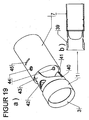
- FIG. 19 shows in representation a) is an exploded perspective view and in representation b) is a side view of an embodiment of a cutting element 1 and a cutter support 7. 18b is a side view.
- the cutting element 1 is characterized in this embodiment again by the fact that it can be detachably inserted into the blade carrier 7 and connected to this.
- the cutting element is provided with a conical chamfer 39 emanating from the peripheral surface, which tapers preferably at an angle of 45 ° to 15 ° to the nominal internal diameter of the cutter carrier 7.
- the conical chamfer 39 is followed by a cylindrical portion 40 whose outer diameter is less than or equal to / as the inner diameter of the cutter carrier 7. This is provided at its end facing the cutting element 1 with a conical portion 41 whose angle of inclination to the conical Bevel 39 is adapted so that the conical chamfer 39 here as in the above-described embodiments of the conical region 41 is applied flat.
- the cylindrical portion 40 passes into at least one, preferably two opposing tabs 43, unlike the embodiment according to FIG. 17 , are flat at the end, so have no thickening.
- the at least one tab has a breakthrough 42 in its middle region, the region facing away from the conical chamfer 39 is arcuate, preferably circular-arc-shaped, while the opposite longitudinal edge of the opening 42 runs in the circumferential direction of the cutting element 1, thus parallel to the conical chamfer 39 or the conical region 41.
- the inner surface of the cutter carrier 7 is provided with at least one wart 44, preferably two opposite warts 44.
- the number of warts practically freely selectable. It is also possible to provide two or four pairs of opposing warts 44, which can then engage in the openings 42 of the tabs 43 of the cutting element 1.
- the number of tabs is here - as in the Figures 17 and 18 shown embodiments - freely selectable. It can also be provided more than two tabs.
- the warts 44 also have the task of captively holding the cutting element in the blade carrier 7, in particular to transfer tensile forces on the cutting element 1 when retracting the hollow drill, so that it can be safely pulled out of the well.
- the warts 44 serve to transmit torque forces from the blade carrier 7 on the cutting element 1, wherein also a torque is transmitted from the conical portion 41 to the conical chamfer 39.
- the warts 44 are preferably circular, but can be provided on the rear side facing away from the cutting element 1 with a contour which is adapted to the contour of the openings 42. As a result, it can be achieved that the rear side of the warts 44 lies flat against the region of the opening 42 in the form of a circular arc.
- the warts in the embodiments according to the Figures 18 and 19 can be flattened on their side facing the cutting element 1 side, so they can drop in the direction of the inner surface of the cutter support 7, so that the cutting element 1 can be easily inserted into the blade carrier 7:
- the tabs 43 can slide on the falling edges of the warts 44 along and pressed inwardly until the warts 44 engage the apertures 42, practically snap.
- the wall of the cutter support 7 has an opening 45.
- FIG. 19 is here also merely exemplified that the openings 45 are formed as an elongated rectangle and extend in the circumferential direction.
- the openings 45 are formed as an elongated rectangle and extend in the circumferential direction.
- circular openings can be provided in order to exert unlocking forces on the tabs 43 can.
- FIG. 17 are holding lugs provided in the embodiment according to the Figures 18 and 19 is provided that at least one wart 44 engages in an opening, whose contour is formed so that an additional torque is transferable.
- the wart rests against the side walls of the opening 42, or by the fact that the opening has an arcuate contour on which during a relative rotation between the cutting element 1 and blade holder 7, the wart 44 slides along so that additional tensile forces the cutting element 1 are exerted, and the conical chamfer 19 rests with increased force on a conical portion 41 of the cutter support 7.
- the structure of the hollow drill is very simple and inexpensive to implement.
Landscapes
- Engineering & Computer Science (AREA)
- Mechanical Engineering (AREA)
- Life Sciences & Earth Sciences (AREA)
- Forests & Forestry (AREA)
- Drilling Tools (AREA)
- Perforating, Stamping-Out Or Severing By Means Other Than Cutting (AREA)
Abstract
Claims (22)
- Elément de coupe pour une mèche creuse avec une portion de coupe (3) et une partie en substance cylindrique (4, 4.1, 4.2) qui sur le côté intérieure présente des renfoncements disposés en intervalles - de préférence réguliers - s'ouvrant en direction de la portion de coupe (3) où la partie en substance cylindrique (4, 4.1, 4.2) présente une forme intérieure polygonale caractérisée en ce que les arêtes (7) sont liées ensemble par chaque fois un renfoncement (5) et la forme intérieure polygonale se change de manière conique en une forme intérieure cylindrique (4.2) au niveau d'un côté en face de la portion de coupe.
- Elément de coupe selon revendication 1, caractérisé en ce que les renfoncements (5) sont orientés en direction axiale.
- Elément de coupe selon revendication 1 ou 2, caractérisé en ce que les renfoncements (5) sont disposés en direction circonférentielle avec un écart entre eux.
- Elément de coupe selon revendication 1 ou 2, caractérisé en ce que les renfoncements (5) en forme hélicoïdale sont orientés sur la partie intérieure de la partie en substance cylindrique (4, 4.1, 4.2).
- Elément de coupe selon une des revendications précédentes, caractérisé en ce que l'élément de coupe (1) se compose de carbure de tungstène et/ou de céramique et/ou comporte un revêtement diamant.
- Elément de coupe selon une des revendications précédentes, caractérisé en ce que la portion de coupe (3) comporte des renfoncements supplémentaires (9) orientés de préférence en forme hélicoïdale.
- Elément de coupe selon une des revendications précédentes, caractérisé en ce que dans la partie en substance cylindrique (4, 4.1, 4.2), un lubrifiant est intégré en particulier à l'intérieur des renfoncements (5).
- Elément de coupe selon revendication 7, caractérisé en ce que le lubrifiant passe dans l'état liquide lors du dépassement d'une température limite déterminée.
- Elément de coupe selon une des revendications précédentes, caractérisé en ce que les renfoncements (5), sont réalisés sous forme d'entailles (11).
- Elément de coupe selon revendication 9, caractérisé en ce que dans la partie en substance cylindrique (4, 4.1, 4.2) une bague de préférence de forme cylindrique (19) est disposée.
- Elément de coupe selon une des revendications précédentes, caractérisé par au moins une patte (36, 43), qui débute sur le côté de l'élément de coupe (1) détourné par rapport à la portion de coupe (31) et qu'on peut insérer dans un support de lame (7).
- Elément de coupe selon revendication 11, caractérisé en ce que l'au moins une patte (36, 43) comporte un dispositif de support.
- Elément de coupe selon revendication 11 ou 12 , caractérisé en ce que l'au moins une patte (36, 43) comporte un renfoncement ou un évidement, dans lequel une saillie partant de la partie intérieure du support de lame (7) peut venir en prise.
- Elément de coupe selon revendication 13, caractérisé en ce que le renfoncement ou l'évidement présente un contour en substance triangulaire.
- Elément de coupe selon revendication 14, caractérisé en ce que le renfoncement ou l'évidemment présente un contour incurvé, qui - vu à partir de la portion de coupe (3)- est formé de façon concave et sert de surface d'appui pour la saillie du support de lame (7).
- Elément de coupe selon revendication 15, caractérisé en ce que le contour est ainsi disposé et coordonné avec la saillie que lors d'une rotation relative entre élément de coupe (1) et support de lame (7) agissant en direction axiale - les forces de serrage entre ces éléments augmentent.
- Support de lame pour un élément de coupe selon une des revendications 1 à 16, présentant une ouverture (13) pour l'élément de coupe (1), caractérisé par une partie réalisée de manière conique (16, 18), dans laquelle l'angle conique s'ouvre pour l'élément de coupe dans le sens contraire de l'ouverture (13), et des augmentations dans la partie conique pour la réception des renfoncements (5,11) de l'élément de coupe (1).
- Support de lame selon revendication 17, caractérisé en ce que l'angle conique se situe entre 1° - 6°.
- Support de lame selon revendication 17 ou 18, caractérisé en ce que, se rattache dans le sens contraire de l'ouverture (13) pour l'élément de coupe (1), à la partie réalisée de manière conique (16, 18), une partie cylindrique (20) qui présente de préférence un diamètre plus petit que la partie réalisée de manière conique (16, 18), à l'endroit où il est le plus éloigné de l'ouverture (13) pour l'élément de coupe (1).
- Support de lame selon une des revendications 17 à 19, caractérisé par au minimum un renfoncement ou un évidement dans la paroi, dans laquelle s'enclenche un dispositif de support de l'élément de coupe (1).
- Support de lame selon revendications 17 à 20, caractérisé par au moins un franchissement, au travers de laquelle l'au moins une patte de l'élément de coupe (1) est escamotable avec une force de déverrouillage.
- Mèche creuse avec un élément de coupe selon une des revendications 1 à 16 et un support de lame, en particulier selon une des revendications 17 à 21, où l'élément de coupe (1) et le support de lame (7) sont réalisés comme des éléments séparés.
Applications Claiming Priority (2)
| Application Number | Priority Date | Filing Date | Title |
|---|---|---|---|
| DE102004057542A DE102004057542A1 (de) | 2004-11-30 | 2004-11-30 | Schneideelement und Schneidenträger für einen Hohlbohrer |
| PCT/EP2005/012764 WO2006058719A2 (fr) | 2004-11-30 | 2005-11-30 | Element de coupe, support de lames et meche creuse |
Publications (2)
| Publication Number | Publication Date |
|---|---|
| EP1817128A2 EP1817128A2 (fr) | 2007-08-15 |
| EP1817128B1 true EP1817128B1 (fr) | 2009-07-22 |
Family
ID=35801442
Family Applications (1)
| Application Number | Title | Priority Date | Filing Date |
|---|---|---|---|
| EP05818386A Expired - Lifetime EP1817128B1 (fr) | 2004-11-30 | 2005-11-30 | Element de coupe, support de lames et meche creuse |
Country Status (5)
| Country | Link |
|---|---|
| US (1) | US7785047B2 (fr) |
| EP (1) | EP1817128B1 (fr) |
| JP (1) | JP2008521626A (fr) |
| DE (2) | DE102004057542A1 (fr) |
| WO (1) | WO2006058719A2 (fr) |
Families Citing this family (16)
| Publication number | Priority date | Publication date | Assignee | Title |
|---|---|---|---|---|
| USD527233S1 (en) | 2004-08-23 | 2006-08-29 | Irwin Industrial Tool Company | Colored reciprocating saw blade |
| CN101489743A (zh) * | 2006-05-22 | 2009-07-22 | 米其林技术公司 | 用于对橡胶制品进行钻孔的装置和方法 |
| JP5063236B2 (ja) * | 2007-07-23 | 2012-10-31 | 株式会社リコー | シートパンチ装置 |
| DE102007037229A1 (de) | 2007-08-07 | 2009-02-12 | Rieter Ingolstadt Gmbh | Auflösewalze mit Clipverbindung |
| DE102009047920A1 (de) * | 2008-10-06 | 2010-07-29 | Holzhauer Gmbh & Co. Kg | Widerstandsschweißelektrode |
| US9586270B2 (en) | 2010-01-13 | 2017-03-07 | Irwin Industrial Tool Company | Coated hole cutter |
| US9782839B2 (en) | 2010-01-13 | 2017-10-10 | Irwin Industrial Tool Company | Hole cutter with chip egress aperture |
| US10137507B2 (en) | 2010-01-13 | 2018-11-27 | Irwin Industrial Tool Company | Hole cutter with multiple fulcrums |
| US9724766B2 (en) | 2010-01-13 | 2017-08-08 | Irwin Industrial Tool Company | Hole cutter with multiple fulcrums |
| US9808869B2 (en) | 2010-01-13 | 2017-11-07 | Irwin Industrial Tool Company | Hole cutter with chip egress aperture |
| USD690334S1 (en) | 2010-01-13 | 2013-09-24 | Irwin Industrial Tool Company | Hole saw |
| US9884374B2 (en) | 2015-09-03 | 2018-02-06 | Irwin Industrial Tool Company | Hole cutter with multiple fulcrums |
| CN103770152B (zh) * | 2013-12-31 | 2015-12-09 | 郑州轻工业学院 | 一种用于软质材料规则取孔的中空刀具 |
| WO2018146436A1 (fr) * | 2017-02-13 | 2018-08-16 | Derek Alfred Ward | Scie-cloche |
| USD845362S1 (en) | 2017-12-04 | 2019-04-09 | Black & Decker Inc. | Holesaw |
| CN114290426A (zh) * | 2021-12-28 | 2022-04-08 | 东莞市泊尔非特五金有限公司 | 一种票务装订机用改进型打孔空心钻刀组件 |
Family Cites Families (32)
| Publication number | Priority date | Publication date | Assignee | Title |
|---|---|---|---|---|
| US1927865A (en) * | 1925-09-03 | 1933-09-26 | Fyrac Mfg Co | Glass cutter |
| US2412939A (en) | 1945-06-25 | 1946-12-24 | Earl F Aston | Core drill |
| US2847885A (en) * | 1956-08-02 | 1958-08-19 | Cleveland Twist Drill Co | Deep hole drill |
| US2947206A (en) * | 1959-10-13 | 1960-08-02 | James H Flanagan | Self-lubricating trepanning drill |
| US3153885A (en) * | 1961-10-09 | 1964-10-27 | Chauncey A R Keller | Cyclindrical cutter device |
| US3243924A (en) * | 1964-01-06 | 1966-04-05 | Wheel Trueing Tool Co | Diamond drill bit |
| US3382743A (en) | 1965-12-08 | 1968-05-14 | Walter Trevathan Corp | Drilling machine bit means |
| US3374696A (en) * | 1966-02-23 | 1968-03-26 | Walter Trevathan Corp | Bit means |
| US3494348A (en) * | 1967-02-20 | 1970-02-10 | Trw Inc | Core drill |
| DE7226347U (de) * | 1972-07-15 | 1976-01-08 | Borchert, Otto, 7417 Dettingen | Hohlbohrwerkzeug zur herstellung von bohrungen, insbesondere langen durchgehenden bohrungen grossen durchmessers |
| US4072441A (en) * | 1976-04-15 | 1978-02-07 | Parker Manufacturing Company | Hole saw |
| US4077737A (en) * | 1976-10-18 | 1978-03-07 | Morse Mansfield K | Integral hole saw and arbor construction |
| JPS55103108U (fr) * | 1979-01-10 | 1980-07-18 | ||
| DE2935565A1 (de) * | 1979-09-03 | 1981-03-12 | Bopp & Reuther Gmbh, 6800 Mannheim | Ventilanbohrarmatur. |
| JPS5723919U (fr) * | 1980-07-14 | 1982-02-06 | ||
| FR2535635A1 (en) * | 1982-11-10 | 1984-05-11 | Mailliet Robert | Method for drilling an opening in a wall without producing waste on the side of its emergence and device for implementing this method |
| JPS59107815A (ja) * | 1982-12-07 | 1984-06-22 | Kodera Asaji | コアドリル |
| JPH0618727Y2 (ja) * | 1987-05-08 | 1994-05-18 | 山本 博之 | ホ−ルソ− |
| DE3810540A1 (de) * | 1988-03-28 | 1989-10-19 | Hilti Ag | Bohrwerkzeug |
| US5098234A (en) | 1988-07-27 | 1992-03-24 | Verosol Usa Inc. | Hollow drill for fabric and the like |
| DE8901906U1 (de) * | 1989-02-17 | 1989-05-24 | Entwicklungszentrum für Zerspanungstechnik GmbH & Co KG, 7630 Lahr | Vorrichtung zum Entfernen beschädigter Stellen in Gummiteilen |
| CA2081033C (fr) * | 1992-10-21 | 1995-08-08 | Barry Wolf | Faisceau de tubes de forage |
| JP2960879B2 (ja) | 1995-11-01 | 1999-10-12 | 三和ダイヤモンド工業株式会社 | 大口径穴あけ装置および大口径穴あけ装置に用いられるホールソー |
| JPH09267207A (ja) * | 1996-04-03 | 1997-10-14 | Cosmo Koki Co Ltd | 管体穿孔用ホールソー |
| JP3816616B2 (ja) | 1997-01-23 | 2006-08-30 | コスモ工機株式会社 | 管体用ホールソー |
| JPH10328919A (ja) * | 1997-05-30 | 1998-12-15 | Sekisui Chem Co Ltd | 穿孔用カッタ |
| JPH11156617A (ja) | 1997-11-28 | 1999-06-15 | Asahi Glass Co Ltd | ダイヤモンドコアドリル |
| JP2890190B1 (ja) * | 1998-03-31 | 1999-05-10 | 前澤給装工業株式会社 | 配水用ポリエチレン管の穿孔用ホルソ |
| DE29816823U1 (de) * | 1998-09-22 | 1999-10-28 | Hawera Probst GmbH, 88212 Ravensburg | Bohrwerkzeug |
| DE10009721A1 (de) * | 2000-03-01 | 2001-09-06 | Komet Stahlhalter Werkzeuge | Maschinenreibahle und Reibkopf für eine Maschinenreibahle |
| JP2002120218A (ja) * | 2000-10-16 | 2002-04-23 | Ichikawa Seiki:Kk | コンクリート用コアドリル |
| JP2002301614A (ja) * | 2001-04-05 | 2002-10-15 | Mitsubishi Materials Corp | 穿孔工具及び穿孔装置 |
-
2004
- 2004-11-30 DE DE102004057542A patent/DE102004057542A1/de not_active Ceased
-
2005
- 2005-11-30 DE DE502005007760T patent/DE502005007760D1/de not_active Expired - Lifetime
- 2005-11-30 JP JP2007541875A patent/JP2008521626A/ja active Pending
- 2005-11-30 EP EP05818386A patent/EP1817128B1/fr not_active Expired - Lifetime
- 2005-11-30 WO PCT/EP2005/012764 patent/WO2006058719A2/fr not_active Ceased
- 2005-11-30 US US11/720,355 patent/US7785047B2/en not_active Expired - Fee Related
Also Published As
| Publication number | Publication date |
|---|---|
| WO2006058719A2 (fr) | 2006-06-08 |
| US7785047B2 (en) | 2010-08-31 |
| EP1817128A2 (fr) | 2007-08-15 |
| WO2006058719A3 (fr) | 2006-08-10 |
| US20080131223A1 (en) | 2008-06-05 |
| DE102004057542A1 (de) | 2006-06-01 |
| DE502005007760D1 (de) | 2009-09-03 |
| JP2008521626A (ja) | 2008-06-26 |
Similar Documents
| Publication | Publication Date | Title |
|---|---|---|
| EP1817128B1 (fr) | Element de coupe, support de lames et meche creuse | |
| EP1476269B1 (fr) | Outil de coupe rotatif a piece de coupe rapportee interchangeable | |
| EP1996358B1 (fr) | Outil de forage et tête d'outil pour outil de forage | |
| EP1918596B1 (fr) | Rivet aveugle et son utilisation | |
| DE2709830C3 (de) | Zentrumsbohrer zur Bearbeitung von Holz, Kunststoff u.dgl. | |
| DE69914975T2 (de) | Bohrer und seine Herstellungsmethode | |
| WO1997017153A1 (fr) | Outil de perçage avec pointe remplaçable | |
| WO2008049621A2 (fr) | Dispositif de serrage et pince de serrage, corps de base et clé de serrage à cet effet | |
| DE20001825U1 (de) | Schneidwerkzeug | |
| DE2732677A1 (de) | Spannzange | |
| EP2048383B1 (fr) | Vis autoforeuse | |
| DE102014207502B4 (de) | Rotationswerkzeug sowie Werkzeugkopf | |
| DE102013210355B4 (de) | Zerspanungswerkzeug sowie Verfahren zur Herstellung eines Zerspanungswerkzeug | |
| EP3781785B1 (fr) | Trépan de fraisage | |
| DE102024112582A1 (de) | Trockenbaudübel und Verfahren zur Montage des Trockenbaudübels | |
| DE102020204035B4 (de) | Bohrer | |
| DE20204848U1 (de) | Auswechselbare Bohrerspitze und Bohrwerkzeuganordnung | |
| EP2577074B1 (fr) | Vis autotaraudeuse | |
| EP1239985A1 (fr) | Mandrin de serrage | |
| WO2015166062A1 (fr) | Porte-outil | |
| WO2025051555A1 (fr) | Cheville pour cloison sèche et procédé d'ajustement de la cheville pour cloison sèche | |
| DE202008014738U1 (de) | Antriebskupplung sowie Aufnahmeteil und Spannteil für Rotationsantriebe | |
| WO2023041335A1 (fr) | Dispositif d'ancrage à contre-dépouille auto-taraudant | |
| DE102021133386A1 (de) | Selbstschneidender Hinterschnittanker | |
| DE102007043890A1 (de) | Spannvorrichtung sowie Spannzange, Grundkörper und Spannschlüssel dafür |
Legal Events
| Date | Code | Title | Description |
|---|---|---|---|
| PUAI | Public reference made under article 153(3) epc to a published international application that has entered the european phase |
Free format text: ORIGINAL CODE: 0009012 |
|
| 17P | Request for examination filed |
Effective date: 20070531 |
|
| AK | Designated contracting states |
Kind code of ref document: A2 Designated state(s): AT BE BG CH CY CZ DE DK EE ES FI FR GB GR HU IE IS IT LI LT LU LV MC NL PL PT RO SE SI SK TR |
|
| DAX | Request for extension of the european patent (deleted) | ||
| 17Q | First examination report despatched |
Effective date: 20080313 |
|
| GRAP | Despatch of communication of intention to grant a patent |
Free format text: ORIGINAL CODE: EPIDOSNIGR1 |
|
| GRAS | Grant fee paid |
Free format text: ORIGINAL CODE: EPIDOSNIGR3 |
|
| GRAA | (expected) grant |
Free format text: ORIGINAL CODE: 0009210 |
|
| AK | Designated contracting states |
Kind code of ref document: B1 Designated state(s): AT BE BG CH CY CZ DE DK EE ES FI FR GB GR HU IE IS IT LI LT LU LV MC NL PL PT RO SE SI SK TR |
|
| REG | Reference to a national code |
Ref country code: GB Ref legal event code: FG4D Free format text: NOT ENGLISH |
|
| REG | Reference to a national code |
Ref country code: CH Ref legal event code: EP |
|
| REG | Reference to a national code |
Ref country code: IE Ref legal event code: FG4D |
|
| REF | Corresponds to: |
Ref document number: 502005007760 Country of ref document: DE Date of ref document: 20090903 Kind code of ref document: P |
|
| NLV1 | Nl: lapsed or annulled due to failure to fulfill the requirements of art. 29p and 29m of the patents act | ||
| PG25 | Lapsed in a contracting state [announced via postgrant information from national office to epo] |
Ref country code: IS Free format text: LAPSE BECAUSE OF FAILURE TO SUBMIT A TRANSLATION OF THE DESCRIPTION OR TO PAY THE FEE WITHIN THE PRESCRIBED TIME-LIMIT Effective date: 20091122 Ref country code: SE Free format text: LAPSE BECAUSE OF FAILURE TO SUBMIT A TRANSLATION OF THE DESCRIPTION OR TO PAY THE FEE WITHIN THE PRESCRIBED TIME-LIMIT Effective date: 20090722 Ref country code: ES Free format text: LAPSE BECAUSE OF FAILURE TO SUBMIT A TRANSLATION OF THE DESCRIPTION OR TO PAY THE FEE WITHIN THE PRESCRIBED TIME-LIMIT Effective date: 20091102 Ref country code: FI Free format text: LAPSE BECAUSE OF FAILURE TO SUBMIT A TRANSLATION OF THE DESCRIPTION OR TO PAY THE FEE WITHIN THE PRESCRIBED TIME-LIMIT Effective date: 20090722 Ref country code: LT Free format text: LAPSE BECAUSE OF FAILURE TO SUBMIT A TRANSLATION OF THE DESCRIPTION OR TO PAY THE FEE WITHIN THE PRESCRIBED TIME-LIMIT Effective date: 20090722 |
|
| PG25 | Lapsed in a contracting state [announced via postgrant information from national office to epo] |
Ref country code: PL Free format text: LAPSE BECAUSE OF FAILURE TO SUBMIT A TRANSLATION OF THE DESCRIPTION OR TO PAY THE FEE WITHIN THE PRESCRIBED TIME-LIMIT Effective date: 20090722 Ref country code: SI Free format text: LAPSE BECAUSE OF FAILURE TO SUBMIT A TRANSLATION OF THE DESCRIPTION OR TO PAY THE FEE WITHIN THE PRESCRIBED TIME-LIMIT Effective date: 20090722 Ref country code: NL Free format text: LAPSE BECAUSE OF FAILURE TO SUBMIT A TRANSLATION OF THE DESCRIPTION OR TO PAY THE FEE WITHIN THE PRESCRIBED TIME-LIMIT Effective date: 20090722 Ref country code: LV Free format text: LAPSE BECAUSE OF FAILURE TO SUBMIT A TRANSLATION OF THE DESCRIPTION OR TO PAY THE FEE WITHIN THE PRESCRIBED TIME-LIMIT Effective date: 20090722 |
|
| REG | Reference to a national code |
Ref country code: IE Ref legal event code: FD4D |
|
| PG25 | Lapsed in a contracting state [announced via postgrant information from national office to epo] |
Ref country code: PT Free format text: LAPSE BECAUSE OF FAILURE TO SUBMIT A TRANSLATION OF THE DESCRIPTION OR TO PAY THE FEE WITHIN THE PRESCRIBED TIME-LIMIT Effective date: 20091122 Ref country code: BG Free format text: LAPSE BECAUSE OF FAILURE TO SUBMIT A TRANSLATION OF THE DESCRIPTION OR TO PAY THE FEE WITHIN THE PRESCRIBED TIME-LIMIT Effective date: 20091022 |
|
| PG25 | Lapsed in a contracting state [announced via postgrant information from national office to epo] |
Ref country code: RO Free format text: LAPSE BECAUSE OF FAILURE TO SUBMIT A TRANSLATION OF THE DESCRIPTION OR TO PAY THE FEE WITHIN THE PRESCRIBED TIME-LIMIT Effective date: 20090722 Ref country code: IE Free format text: LAPSE BECAUSE OF FAILURE TO SUBMIT A TRANSLATION OF THE DESCRIPTION OR TO PAY THE FEE WITHIN THE PRESCRIBED TIME-LIMIT Effective date: 20090722 Ref country code: EE Free format text: LAPSE BECAUSE OF FAILURE TO SUBMIT A TRANSLATION OF THE DESCRIPTION OR TO PAY THE FEE WITHIN THE PRESCRIBED TIME-LIMIT Effective date: 20090722 Ref country code: DK Free format text: LAPSE BECAUSE OF FAILURE TO SUBMIT A TRANSLATION OF THE DESCRIPTION OR TO PAY THE FEE WITHIN THE PRESCRIBED TIME-LIMIT Effective date: 20090722 Ref country code: CZ Free format text: LAPSE BECAUSE OF FAILURE TO SUBMIT A TRANSLATION OF THE DESCRIPTION OR TO PAY THE FEE WITHIN THE PRESCRIBED TIME-LIMIT Effective date: 20090722 |
|
| PLBE | No opposition filed within time limit |
Free format text: ORIGINAL CODE: 0009261 |
|
| STAA | Information on the status of an ep patent application or granted ep patent |
Free format text: STATUS: NO OPPOSITION FILED WITHIN TIME LIMIT |
|
| BERE | Be: lapsed |
Owner name: JAUCH, ACHIM Effective date: 20091130 |
|
| PG25 | Lapsed in a contracting state [announced via postgrant information from national office to epo] |
Ref country code: SK Free format text: LAPSE BECAUSE OF FAILURE TO SUBMIT A TRANSLATION OF THE DESCRIPTION OR TO PAY THE FEE WITHIN THE PRESCRIBED TIME-LIMIT Effective date: 20090722 |
|
| 26N | No opposition filed |
Effective date: 20100423 |
|
| PG25 | Lapsed in a contracting state [announced via postgrant information from national office to epo] |
Ref country code: MC Free format text: LAPSE BECAUSE OF NON-PAYMENT OF DUE FEES Effective date: 20091130 |
|
| REG | Reference to a national code |
Ref country code: CH Ref legal event code: PL |
|
| PG25 | Lapsed in a contracting state [announced via postgrant information from national office to epo] |
Ref country code: CH Free format text: LAPSE BECAUSE OF NON-PAYMENT OF DUE FEES Effective date: 20091130 Ref country code: BE Free format text: LAPSE BECAUSE OF NON-PAYMENT OF DUE FEES Effective date: 20091130 Ref country code: LI Free format text: LAPSE BECAUSE OF NON-PAYMENT OF DUE FEES Effective date: 20091130 Ref country code: GR Free format text: LAPSE BECAUSE OF FAILURE TO SUBMIT A TRANSLATION OF THE DESCRIPTION OR TO PAY THE FEE WITHIN THE PRESCRIBED TIME-LIMIT Effective date: 20091023 |
|
| PGFP | Annual fee paid to national office [announced via postgrant information from national office to epo] |
Ref country code: AT Payment date: 20101130 Year of fee payment: 6 Ref country code: FR Payment date: 20101214 Year of fee payment: 6 |
|
| PG25 | Lapsed in a contracting state [announced via postgrant information from national office to epo] |
Ref country code: IT Free format text: LAPSE BECAUSE OF FAILURE TO SUBMIT A TRANSLATION OF THE DESCRIPTION OR TO PAY THE FEE WITHIN THE PRESCRIBED TIME-LIMIT Effective date: 20090722 |
|
| PGFP | Annual fee paid to national office [announced via postgrant information from national office to epo] |
Ref country code: GB Payment date: 20101130 Year of fee payment: 6 |
|
| PG25 | Lapsed in a contracting state [announced via postgrant information from national office to epo] |
Ref country code: LU Free format text: LAPSE BECAUSE OF NON-PAYMENT OF DUE FEES Effective date: 20091130 |
|
| PG25 | Lapsed in a contracting state [announced via postgrant information from national office to epo] |
Ref country code: HU Free format text: LAPSE BECAUSE OF FAILURE TO SUBMIT A TRANSLATION OF THE DESCRIPTION OR TO PAY THE FEE WITHIN THE PRESCRIBED TIME-LIMIT Effective date: 20100123 |
|
| PG25 | Lapsed in a contracting state [announced via postgrant information from national office to epo] |
Ref country code: TR Free format text: LAPSE BECAUSE OF FAILURE TO SUBMIT A TRANSLATION OF THE DESCRIPTION OR TO PAY THE FEE WITHIN THE PRESCRIBED TIME-LIMIT Effective date: 20090722 |
|
| PG25 | Lapsed in a contracting state [announced via postgrant information from national office to epo] |
Ref country code: CY Free format text: LAPSE BECAUSE OF FAILURE TO SUBMIT A TRANSLATION OF THE DESCRIPTION OR TO PAY THE FEE WITHIN THE PRESCRIBED TIME-LIMIT Effective date: 20090722 |
|
| GBPC | Gb: european patent ceased through non-payment of renewal fee |
Effective date: 20111130 |
|
| REG | Reference to a national code |
Ref country code: FR Ref legal event code: ST Effective date: 20120731 |
|
| REG | Reference to a national code |
Ref country code: AT Ref legal event code: MM01 Ref document number: 437018 Country of ref document: AT Kind code of ref document: T Effective date: 20111130 |
|
| PG25 | Lapsed in a contracting state [announced via postgrant information from national office to epo] |
Ref country code: GB Free format text: LAPSE BECAUSE OF NON-PAYMENT OF DUE FEES Effective date: 20111130 |
|
| PG25 | Lapsed in a contracting state [announced via postgrant information from national office to epo] |
Ref country code: FR Free format text: LAPSE BECAUSE OF NON-PAYMENT OF DUE FEES Effective date: 20111130 |
|
| PG25 | Lapsed in a contracting state [announced via postgrant information from national office to epo] |
Ref country code: AT Free format text: LAPSE BECAUSE OF NON-PAYMENT OF DUE FEES Effective date: 20111130 |
|
| PGFP | Annual fee paid to national office [announced via postgrant information from national office to epo] |
Ref country code: DE Payment date: 20141127 Year of fee payment: 10 |
|
| REG | Reference to a national code |
Ref country code: DE Ref legal event code: R119 Ref document number: 502005007760 Country of ref document: DE |
|
| PG25 | Lapsed in a contracting state [announced via postgrant information from national office to epo] |
Ref country code: DE Free format text: LAPSE BECAUSE OF NON-PAYMENT OF DUE FEES Effective date: 20160601 |