EP1819030A1 - Moteur/Générateur - Google Patents
Moteur/Générateur Download PDFInfo
- Publication number
- EP1819030A1 EP1819030A1 EP07102145A EP07102145A EP1819030A1 EP 1819030 A1 EP1819030 A1 EP 1819030A1 EP 07102145 A EP07102145 A EP 07102145A EP 07102145 A EP07102145 A EP 07102145A EP 1819030 A1 EP1819030 A1 EP 1819030A1
- Authority
- EP
- European Patent Office
- Prior art keywords
- rotor
- shorting
- rotor member
- permanent magnets
- drive
- Prior art date
- Legal status (The legal status is an assumption and is not a legal conclusion. Google has not performed a legal analysis and makes no representation as to the accuracy of the status listed.)
- Granted
Links
Images




Classifications
-
- H—ELECTRICITY
- H02—GENERATION; CONVERSION OR DISTRIBUTION OF ELECTRIC POWER
- H02K—DYNAMO-ELECTRIC MACHINES
- H02K21/00—Synchronous motors having permanent magnets; Synchronous generators having permanent magnets
- H02K21/02—Details
- H02K21/021—Means for mechanical adjustment of the excitation flux
- H02K21/028—Means for mechanical adjustment of the excitation flux by modifying the magnetic circuit within the field or the armature, e.g. by using shunts, by adjusting the magnets position, by vectorial combination of field or armature sections
-
- H—ELECTRICITY
- H02—GENERATION; CONVERSION OR DISTRIBUTION OF ELECTRIC POWER
- H02K—DYNAMO-ELECTRIC MACHINES
- H02K1/00—Details of the magnetic circuit
- H02K1/06—Details of the magnetic circuit characterised by the shape, form or construction
- H02K1/22—Rotating parts of the magnetic circuit
- H02K1/27—Rotor cores with permanent magnets
- H02K1/2706—Inner rotors
- H02K1/272—Inner rotors the magnetisation axis of the magnets being perpendicular to the rotor axis
- H02K1/274—Inner rotors the magnetisation axis of the magnets being perpendicular to the rotor axis the rotor consisting of two or more circumferentially positioned magnets
- H02K1/2753—Inner rotors the magnetisation axis of the magnets being perpendicular to the rotor axis the rotor consisting of two or more circumferentially positioned magnets the rotor consisting of magnets or groups of magnets arranged with alternating polarity
- H02K1/278—Surface mounted magnets; Inset magnets
-
- H—ELECTRICITY
- H02—GENERATION; CONVERSION OR DISTRIBUTION OF ELECTRIC POWER
- H02K—DYNAMO-ELECTRIC MACHINES
- H02K21/00—Synchronous motors having permanent magnets; Synchronous generators having permanent magnets
- H02K21/12—Synchronous motors having permanent magnets; Synchronous generators having permanent magnets with stationary armatures and rotating magnets
- H02K21/14—Synchronous motors having permanent magnets; Synchronous generators having permanent magnets with stationary armatures and rotating magnets with magnets rotating within the armatures
- H02K21/16—Synchronous motors having permanent magnets; Synchronous generators having permanent magnets with stationary armatures and rotating magnets with magnets rotating within the armatures having annular armature cores with salient poles
-
- H—ELECTRICITY
- H02—GENERATION; CONVERSION OR DISTRIBUTION OF ELECTRIC POWER
- H02K—DYNAMO-ELECTRIC MACHINES
- H02K7/00—Arrangements for handling mechanical energy structurally associated with dynamo-electric machines, e.g. structural association with mechanical driving motors or auxiliary dynamo-electric machines
- H02K7/10—Structural association with clutches, brakes, gears, pulleys or mechanical starters
- H02K7/12—Structural association with clutches, brakes, gears, pulleys or mechanical starters with auxiliary limited movement of stators, rotors or core parts, e.g. rotors axially movable for the purpose of clutching or braking
-
- H—ELECTRICITY
- H02—GENERATION; CONVERSION OR DISTRIBUTION OF ELECTRIC POWER
- H02K—DYNAMO-ELECTRIC MACHINES
- H02K16/00—Machines with more than one rotor or stator
Definitions
- the present invention relates to a motor/generator and particularly, but not exclusively, to a motor/generator in which an induced voltage is reduced. More specifically, the present invention relates to a motor/generator in which the magnetic flux flowing in a magnetic circuit that is formed between a rotor and a stator of the motor/generator is reduced by shorting the magnetic flux of permanent magnets of the motor/generator. Aspects of the invention also relate to an apparatus, to a method and to a vehicle.
- Japanese Laid-Open Patent Publication No. 2001-314053 discloses a conventional permanent magnet motor/generator provided.
- the conventional motor/generator disclosed in this reference is configured to short the magnetic flux of the permanent magnets when the induced voltage becomes high while a rotor rotates at high speeds.
- Such conventional motor/generator includes the rotor having a plurality of permanent magnets, a plurality of coils through which the electric current passes, a stator configured and arranged to drive the rotor by forming a magnetic circuit between the coils and the permanent magnets, and a shorting member.
- the shorting member is configured and arranged to switch between a shorted state in which the shorting member establishes a short-circuit in the magnetic flux of the permanent magnets and a normal state in which the shorting member does not establish a short-circuit in the magnetic flux.
- an actuator is provided to drive the shorting member to switch between the shorted state and the normal state.
- the size of the motor/generator tends to be relatively large because it is necessary to provide a separate actuator to operate the shorting member in order to switch between the shorted state and the normal state.
- Embodiments of the invention may provide a motor/generator that can establish a short-circuit in the magnetic flux of the permanent magnets without the need to provide a separate actuator.
- Other aims and advantages of the invention will become apparent from the following description claims and drawings.
- a motor/generator comprising a rotor member having a plurality of permanent magnets, a shorting member configured and arranged to selectively establish a short-circuit in magnetic flux of the permanent magnets of the rotor member to switch between a normal state in which the magnetic flux of the permanent magnets is not shorted and a shorted state in which the magnetic flux of the permanent magnets is shorted and a stator having a plurality of coils configured and arranged to be energized with a composite electrical current including first and second current components, the stator being further configured and arranged to form a first magnetic circuit between the coils and the permanent magnets of the rotor member with the first current component of the composite electrical current to drive the rotor member and to form a second magnetic circuit between the coils and the shorting member with the second current component of the composite electrical current to selectively switch between the normal state and the shorted state.
- the shorting member includes an annular body having a plurality of magnetic pole sections configured and arranged to form a path for the second magnetic circuit, the shorting member being disposed adjacent to the rotor member such that the shorting member is rotatable relative to the rotor member, the shorting member being configured and arranged to achieve the normal state when the shorting member is positioned relative to the rotor member such that each of the magnetic pole sections do not straddle the permanent magnets disposed adjacent to each other, and to achieve the shorted state when the shorting member is positioned relative to the rotor member such that at least one of the magnetic pole sections straddle two adjacent permanent magnets.
- a number of the magnetic pole sections that is equal to one half of a number of the permanent magnets of the rotor member.
- the motor/generator may comprise a stopper configured and arranged to limit a relative displacement between the shorting member and the rotor member to within a prescribed amount.
- the motor/generator may comprise an elastic member disposed between the shorting member and the rotor member.
- the elastic member exerts a biasing force between the shorting member and the rotor member.
- the rotor member includes an annular first rotor section and an annular second rotor section with the first and second rotor sections of the rotor being configured and arranged to rotate about a rotational axis as an integral unit.
- the shorting member may be disposed between the first rotor section and the second rotor section of the rotor.
- the stator faces the rotor member and the shorting member in a radial direction with respect to the rotational axis of the rotor such that a radial gap exists between the stator and the rotor member and between the stator and the shorting member.
- the first and second rotor sections of the rotor member may be disposed on both axial sides of the shorting member, respectively, such that circumferential surfaces of the first and second rotor sections and the shorting member face the radial gap.
- the stator faces the rotor member and the shorting member in an axial direction with respect to the rotational axis of the rotor such that an axial gap exists between the stator and the rotor member and between the stator and the shorting member.
- the first and second rotor sections of the rotor member may be disposed on both radial sides of the shorting member, respectively, such that axial end surfaces of the first and second rotor sections and the shorting member face the axial gap.
- the magnetic pole sections of the shorting members are equally spaced apart in a circumferential direction of the shorting member.
- a motor/generator comprising drive force outputting means for outputting a drive force, shorting means for establishing a short-circuit in magnetic flux of the drive force outputting means and switching means for selectively operating the drive force outputting means and the shorting means independently using a composite electrical current including first and second current components by forming a first magnetic circuit between the switching means and the drive force outputting means with the first current component of the composite electrical current to drive the drive force outputting means and by forming a second magnetic circuit between the switching means and the shorting means with the second current component of the composite electrical current to selectively switch between the normal state and the shorted state.
- a motor/generator includes a rotor member, a shorting member and a stator.
- the rotor member has a plurality of permanent magnets.
- the shorting member is configured and arranged to selectively establish a short-circuit in magnetic flux of the permanent magnets of the rotor member to switch between a normal state in which the magnetic flux of the permanent magnets is not shorted and a shorted state in which the magnetic flux of the permanent magnets is shorted.
- the stator has a plurality of coils configured and arranged to be energized with a composite electrical current including first and second current components.
- the stator is further configured and arranged to form a first magnetic circuit between the coils and the permanent magnets of the rotor member with the first current component of the composite electrical current to drive the rotor member and to form a second magnetic circuit between the coils and the shorting member with the second current component of the composite electrical current to selectively switch between the normal state and the shorted state.
- Figure 1(a) a motor/generator is illustrated in accordance with a first embodiment of the present invention.
- Figure 1(a) is a simplified schematic view illustrating a structure of the motor/generator in accordance with the first embodiment.
- the motor/generator of the first embodiment includes a rotor unit 1, a rotary shaft 2 and a stator 3.
- the motor/generator is arranged as a radial gap structure in which the rotor unit 1 and the stator 3 are arranged radially relative to each other such that a radial gap 4 (radial air gap) is formed between the rotor unit 1 and the stator 3.
- the rotor unit 1 and the stator 3 are formed in generally cylindrical shapes.
- the rotor unit 1 and the stator 3 are coaxially arranged so that the rotor unit 1 is disposed radially inward of the stator 3.
- the rotor unit 1 includes a drive rotor member 1A (rotor member) and a shorting rotor member 1B (shorting member).
- the drive rotor member 1A has a plurality of permanent magnets 8 disposed on the circumferential surface of the drive rotor member 1A.
- the drive rotor member 1A further comprises a first drive rotor section 1A 1 (first rotor section) and a second drive rotor section 1A 2 (second rotor section).
- the shorting rotor member 1B is configured and arranged to selectively establish a short-circuit in the magnetic flux of the permanent magnets 8 of the drive rotor member 1A.
- the drive rotor member 1A and the shorting rotor member 1B are configured and arranged to rotate at the same speed (as an integral unit) during normal conditions such that the same phase (i.e., the relative positions between the drive rotor member 1A and the shorting rotor member 1B in the rotational direction) is maintained between the drive rotor member 1A and the shorting rotor member 1B.
- a rotational speed difference occurs momentarily between the drive rotor member 1A and the shorting rotor member 1B such that a prescribed phase difference (relative displacement) develops between the drive rotor member 1A and the shorting rotor member 1B.
- the shorting rotor member 1B is driven to rotate by a prescribed amount relative to the drive rotor member 1A.
- the drive rotor member 1A and the shorting rotor member 1B are configured and arranged to rotate again as an integral unit but with the prescribed phase difference between the drive rotor member 1A and the shorting rotor member 1B.
- the rotor unit 1 is arranged as a thick circular disc.
- the rotary shaft 2 is provided in the center portions of both axial sides of the rotor unit 1. Both ends of the rotor rotary shaft 2 are rotatably supported on bearings (not shown).
- the stator 3 is arranged radially outward of the rotor unit 1 such that the radial gap 4 exists between stator 3 disposed on the outside and the rotor unit 1 disposed on the inside.
- the motor/generator of the first embodiment has a radial gap structure.
- the stator 3 has a stator core 16 having the shape of a hollow cylinder, and a plurality of tooth sections 5 arranged at equal intervals (i.e., with equal spacing) along the circumferential direction.
- the tooth sections 5 are arranged on the internal surface of the stator core 16 to protrude radially inwardly.
- Figure 1(a) shows one of the tooth sections 5 in a cross sectional view. As shown in Figure 1(a), a tip end of each of the tooth sections 5 is widened and points toward the rotor unit 1.
- a coil 6 is wound around the perimeter of each of the tooth sections 5, which protrudes in the radial direction.
- the rotor unit 1 has a circumferential surface 7 that faces toward the stator 3 (more specifically, the tooth sections 5 of the stator 3) across the radial gap 4. More specifically, the circumferential surface 7 includes a pair of gap surfaces 7a that form circumferential surfaces of the first and second drive rotor sections 1A 1 and 1A 2 of the drive rotor member 1A and a gap surface 7b that forms a circumferential surface of the shorting rotor member 1B. As shown in Figure 1(a), the permanent magnets 8 of the rotor unit 1 are arranged on the gap surfaces 7a of the first and second drive rotor sections 1A 1 and 1A 2 .
- the shorting rotor member 1B is arranged as an annular body disposed in a center portion the rotor unit 1 in the axial direction.
- Each of the first and second drive rotor sections 1A 1 and 1A 2 is arranged as a generally circular disc-shaped member.
- the shorting rotor member 1B is disposed between the first and second drive rotor sections 1A 1 and 1A 2 in the axial direction.
- first and second drive rotor sections 1A 1 and 1A 2 are arranged on both axially facing sides of the shorting rotor member 1B such that the gap surfaces 7a (circumferential surfaces) of the first and second drive rotor sections 1A 1 and 1A 2 and the gap surface 7b (circumferential surface) of the shorting rotor member 1B face toward the radial gap 4.
- the permanent magnets 8 are provided on the gap surfaces 7a of the first and second drive rotor sections 1A 1 and 1A 2 of the drive rotor member 1A.
- the permanent magnets 8 are arranged such that adjacent permanent magnets 8 have opposite magnetic poles facing radially outwardly.
- the N poles of alternating permanent magnets 8 are oriented radially outward and the S poles of alternating adjacent permanent magnets 8 are oriented radially outward.
- the permanent magnets 8 of the first drive rotor section 1A 1 and the permanent magnets 8 of the second drive rotor section 1A 2 are arranged such that the same magnetic poles (i.e., the N poles or the S poles) are aligned with each other as shown in Figure 1(a).
- FIG 2 is a simplified perspective view of the shorting rotor member 1B.
- the gap surface 7b of the shorting rotor member B is arranged to form a plurality of a plurality of protruding poles 9 (magnetic pole sections) and a recess portions 10 disposed between the protruding poles 9.
- the protruding poles 9 are equally spaced apart in the circumferential direction of the shorting rotor member 1B as shown in Figure 2.
- the protruding poles 9 extend generally radially outwardly from the recess portions 10. Since the shorting rotor member 1B is made of a magnetic material, the protruding poles 9 are also made of a magnetic material.
- the shorting rotor member 1B has a toothed gear shape including the protruding poles 9 and the recess portions 10 alternately arranged along the gap surface 7b.
- the protruding poles 9 and the recess portions 10 of the shorting rotor member 1B are arranged alternately along the circumferential direction.
- the shorting rotor member 1B includes a total of eight protruding poles 9 and eight recess portions 10 around the entire circumference thereof.
- the circumferential length of each of the protruding poles 9 is the same as the circumferential length of each of the recess portions 10.
- each of the first and second drive rotor sections 1A 1 and 1A 2 of the drive rotor member 1A includes a total of sixteen permanent magnets 8 arranged around the circumference thereof.
- each of the first and second drive rotor sections 1A 1 and 1A 2 of the drive rotor member 1A of the drive rotor member 1A includes the permanent magnets 8 that is twice the number of the protruding poles 9 (or the recess portions 10) of the shorting rotor member 1B.
- each of the permanent magnets 8 of the drive rotor member 1A is the same as the circumferential length of each of the protruding poles 9 (and of the recess portions 10) of the shorting rotor member 1B.
- Figure 3 is a vertical cross sectional view of the rotor unit 1 as taken along a plane that is substantially parallel to the rotary shaft 2.
- the rotary shaft 2 is coupled to the drive rotor member 1A.
- the circumferential surface 7 of the rotor unit 1 forms a radially inwardly recessed section 12.
- the recessed section 12 extends around the entire circumference of the drive rotor member 1A and the annular shorting rotor member 1B ( Figure 2) is housed inside the recessed section 12 as shown in Figure 3.
- the first and second drive rotor sections 1A 1 and 1A 2 are arranged axially side by side with the shorting rotor member 1B disposed therebetween, as shown in Figure 1(a).
- the first and second drive rotor sections 1A 1 and 1A 2 are actually connected together at a radial center portion, as shown in Figure 3, to form an integral unit.
- the shorting rotor member 1B is mounted to the recessed section 12 of the drive rotor member 1A on a bearing member 13 such that the shorting rotor member 1B can selectively rotate relative to the drive rotor member 1A.
- the radial thickness of the permanent magnets 8 of the drive rotor member 1A is smaller than the radial dimension of the spaces formed by the recess portions 10 of the shorting rotor member 1B. Since the radial dimension of the spaces formed by the recess portions 10 is larger than the radial thickness of the permanent magnets 8 of the drive rotor member 1A, the magnetic flux of the permanent magnets 8 can be prevented from leaking to the shorting rotor member 1B when the shorting rotor member 1B is not in the shorted state.
- an alternative rotor unit 1' illustrated in Figure 4 can be used in the motor/generator in accordance with the first embodiment.
- the alternative rotor unit 1' includes a drive rotor member 1A' having a first drive rotor section 1A 1 ' and a second drive rotor section 1A 2 ' as separate members as shown in Figure 4.
- the first and second drive rotor sections 1A 1 ' and 1A 2 ' are integrally coupled to the rotor rotary shaft 2 so that the first and second drive rotor sections 1A 1 ' and 1A 2 ' rotate as an integral unit.
- the permanent magnets 8 are mounted on the circumferential surfaces of the first and second drive rotor sections 1A 1 ' and 1A 2 ' as in the first and second drive rotor sections 1A 1 and 1A 2 illustrated in Figure 3.
- the same operational effects can be achieved with the alternative rotor unit 1' shown in Figure 4 as with the rotor unit 1 shown in Figure 3.
- a shorting rotor member 1B' is first mounted to the rotary shaft 2 by the bearing member 13 at a axial center portion 2a of the rotary shaft 2.
- the shorting rotor member 1B' includes the protruding poles 9 and the recess portions 10 similarly to the shorting rotor member 1B.
- the first and second drive rotor sections 1A 1 ' and 1A 2 ' are fixedly secured to the rotary shaft 2.
- This alternative structure illustrated in Figure 4 improves the ease of assembly when the motor/generator is manufactured in accordance with the present invention.
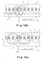
- Figure 1(b) is a diagrammatic partial cross sectional view of the motor/generator in accordance with the first embodiment of the present invention as taken along a section line 1(b)-1(b) of Figure 1(a) with the circumferential direction of the motor/generator being extended in a generally straight line.
- Figure 1(c) is a diagrammatic partial cross sectional view of the motor/generator in accordance with the first embodiment of the present invention as taken along a section line 1(c)-1(c) of Figure 1(a) with the circumferential direction of the motor/generator being extended in a generally straight line.
- the drive rotor member 1A and the shorting rotor member 1B are configured and arranged to be selectively driven separately using a composite electrical current that is supplied to the coils 6 of the stator 3.
- the drive rotor member 1A and the shorting rotor member 1B can be selectively driven to rotate as an integral unit or to rotate relative to each other.
- the coils 6 wound around the tooth sections 5 are connected to an electric circuit E provided with an inverter and a battery as shown in Figure 1(a).
- the electric circuit is configured to supply a composite electrical current to the coils 6.
- the composite electrical current includes a first current component and a second current component.
- the first current component of the composite electrical current is configured to generate a magnetic flux passing radially through the tooth sections 5.
- the composite electrical current is supplied to the coils 6, the coli 6 of each of the tooth sections 5 forms an electromagnet and magnetic forces act between the tip portion of the tooth section 5 and the permanent magnets 8 of the drive rotor member 1A.
- a first magnetic circuit ⁇ 1 is formed as shown in Figure 1(b).
- the magnetic flux passing through a given tooth section 5 passes across the radial gap 4 on the radially inward side of the tooth section 5 and passes through one of the permanent magnets 8 into the inside of the drive rotor member 1A.
- the magnetic flux then passes through another permanent magnet 8, across the radial gap 4, and into the adjacent tooth section 5.
- the magnetic flux then passes to the radially outward side the adjacent tooth section 5 and through the stator core 16 to the original tooth section 5 from which the magnetic flux came, thus completing the first magnetic circuit ⁇ 1.
- the second current component of the composite electrical current is configured to generate a magnetic flux passing radially through some of the tooth sections 5.
- a magnetic force is generated between the tip portions of the tooth sections 5 (electromagnets) and the protruding poles 9 of the shorting rotor member 1B to form a second magnetic circuit ⁇ 2 as shown in Figure 1(c). More specifically, the magnetic flux passing through a given tooth section 5 passes across the radial gap 4 on the radially inward side of the tooth section 5 and passes through one of the protruding poles 9 into the inside of the shorting rotor member 1B.
- the magnetic flux then passes through the adjacent protruding pole 9, across the radial gap 4, and into another of the tooth sections 5.
- the magnetic flux then passes to the radially outward side of the other tooth section 5 and through the stator core 16 to the original tooth section 5 from which the magnetic flux came, thus completing the second magnetic circuit ⁇ 2.
- the torque exerted against the drive rotor member 1A and the torque exerted against the shorting rotor member 1B can be selectively controlled independently.
- the shorting rotor member 1B can be selectively rotated relative to the drive rotor member 1A.
- the drive rotor member 1A and the shorting rotor member 1B are driven with the same torque, the drive rotor member 1A and the shorting rotor member 1B rotate together as an integral unit and there is no relative rotation of the shorting rotor member 1B with respect to the drive rotor member 1A.
- Figure 5 is a diagrammatic view illustrating the relationship of the relative positioning between the driver rotor member 1A and the shorting rotor member 1B in the normal state.
- Figure 5 shows the circumferentially arranged permanent magnets 8, the protruding poles 9, and the recess portions 10 with the circumferential direction of the rotor unit 1 being extended into a generally straight line.
- the rotational speed of the rotor unit 1 is low, i.e., below a prescribed rotational speed, or when the vehicle conditions require the motor/generator be operated in the normal state
- the relative positioning of the drive rotor member 1A and the shorting rotor member 1B is set in the normal state as shown in Figure 5.
- the protruding poles 9 are positioned such that the protruding poles 9 do not straddle two circumferentially adjacent permanent magnets 8 of each of the first and second drive rotor sections 1A 1 and 1A 2 .
- the circumferential positions of the protruding poles 9 are aligned with the circumferential positions of the permanent magnets 8 so that each of the protruding poles 9 overlaps only one permanent magnet 8 of each of the first and second first drive rotor sections 1A 1 and 1A 2 as viewed in the axial direction.
- the protruding poles 9 do not straddle two circumferentially adjacent permanent magnets 8 (which have opposite polarities). Therefore, the protruding poles 9 do not short-circuit the magnetic flux of the adjacent permanent magnets 8. Consequently, the magnetic flux of the first magnetic circuit ⁇ 1 is large and the motor efficiency can be increased in the normal state.
- Figure 6 is a diagrammatic view illustrating the relationship of the relative positioning between the driver rotor member 1A and the shorting rotor member 1B in the shorted state.
- Figure 6 shows the circumferentially arranged permanent magnets 8, the protruding poles 9, and the recess portions 10 with the circumferential direction extended into a generally straight line.
- the shorting rotor member 1B is driven in the direction indicated with the downward arrow in Figure 6 relative to the drive rotor member 1A such that the relative positioning of the permanent magnets 8 of the drive rotor member 1A and the protruding poles 9 of the shorting rotor member 1B becomes offset in the circumferential direction as shown in Figure 6.
- the motor/generator instead of arranging for the protruding poles 9 to be moved in the rotational direction, it is also acceptable to configure the motor/generator such that the protruding poles 9 are moved in the axial direction of the rotor unit 1 in order to establish a short-circuit in the magnetic flux of the adjacent permanent magnet 8.
- the amount of magnetic flux that is shorted between the adjacent permanent magnets 8 varies depending on whether the protruding poles 9 are straddling two circumferentially adjacent permanent magnets 8 widely (i.e., overlapping two circumferentially adjacent permanent magnets 8 to a large degree) or narrowly (i.e., aligned almost entirely with only one permanent magnet 8 of the adjacent pair and overlapping the other permanent magnet 8 only slightly).
- the amount of shorted magnetic flux is small when the protruding poles 9 are offset only slightly in the circumferential direction from the aligned state shown in Figure 5 (i.e., state in which the protruding poles 9 are aligned with the permanent magnets 8) to a state in which the protruding poles 9 straddle two circumferentially adjacent permanent magnets 8 narrowly.
- the amount of shorted magnetic flux is largest when the protruding poles 9 are shifted even further from the state shown in Figure 6 (i.e., state in which the protruding poles 9 are partially overlapping two circumferentially adjacent permanent magnets 8) to a state in which half of each protruding pole 9 overlaps one permanent magnet 8 and the remaining half of each protruding pole 9 overlaps the other permanent magnet 8 of each pair of each of the first and second drive rotor sections 1A 1 and 1A 2 (i.e., the widest possible straddling state).
- the amount by which the shorting rotor member 1B is shifted relative to the drive rotor member 1A the amount by which the protruding poles 9 straddle two circumferentially adjacent permanent magnets 8 can be varied. Accordingly, the amount of shorted magnetic flux can be changed.
- the composite electrical current is also controlled to establish a short-circuit in the magnetic flux of the permanent magnets 8 when a problem is detected in the battery that supplies electric power to the motor/generator or when a problem is detected in the electric circuit connecting the motor/generator to the battery.
- the induced voltage of the motor/generator can be reduced regardless of the rotational speed of the rotor unit 1 to help preserve the battery or the electric circuit.
- the operating range of the motor/generator can be expanded comparing to comparative examples of a motor/generator.
- Figure 11 is a characteristic diagram illustrating the operating regions (torque region and rotational speed region) of the motor/generator in accordance with the first embodiment and two comparative examples of a motor/generator.
- the horizontal axis indicates the rotor rotational speed and the vertical axis indicates the rotor torque.
- the broken line having longer broken sections is a characteristic curve for a first comparative example of the motor/generator in which priority is given to torque output.
- the motor/generator of the first comparative example is designed such that the rotational speed region is narrow to avoid high induced voltages and the torque region is large.
- the broken line having shorter broken sections is a characteristic curve for a second comparative example in which priority is given to power output.
- the second comparative example of the motor/generator is designed such that the rotational speed region is wide to allow high induced voltages.
- the constant output curve of the second comparative example is larger than for the first comparative example emphasizing torque output but the torque region is narrower as shown in Figure 11.
- the first and second comparative examples represent typical conventional motor/generators. Both of the first and second comparative examples of the motor/generator involve a tradeoff relationship with respect to the rotational speed region and the torque region, i.e., expanding the rotational speed region causes the torque region to become narrower and expanding the torque region causes the rotational speed region to become narrower.
- both the rotational speed region and the torque region can be expanded as indicated with the solid-line curve shown in Figure 11.
- the operating region enclosed by the horizontal axis, vertical axis, and constant output curve shown in Figure 11 can be enlarged. Accordingly, the operating performance of the motor/generator can be greatly improved in accordance with the first embodiment of the present invention.
- the shorting rotor member 1B when the rotational speed of the rotor unit 1 falls below the prescribed rotational speed while the induced voltage is being reduced in the shorted state, the shorting rotor member 1B is driven such that the shorting rotor member 1B rotates relative to the drive rotor member 1A. More specifically, the shorting rotor member 1B is rotated relative to the drive rotor member 1A so that the circumferential positions of the protruding poles 9 of the shorting rotor member 1B are aligned with the circumferential positions of the permanent magnets 8 as shown in Figure 5. As a result, the magnetic flux of the first magnetic circuit ⁇ 1 becomes large and the motor/generator can be operated in the normal state.
- Figures 7(a) and 7(b) illustrate a modified rotor unit 11 that can be used in the motor/generator in accordance with the first embodiment instead of the rotor unit 1 illustrated in Figures 1(a) to 1(c), 3 and 4.
- Figure 7(a) is a lateral cross sectional view of the modified rotor unit 11 taken along a plane that is substantially perpendicular to the rotary shaft 2.
- Figure 7(b) is a cross sectional view taken along a section line 7(b)-7(b) of Figure 7(a).
- a stopper 50 is provided that is configured to limit a phase difference (relative displacement) between a drive rotor member 11A and a shorting rotor member 11B within a prescribed amount when the drive rotor member 11A and the shorting rotor member 11B are rotated relative to each other to produce the phase difference.
- the stopper 50 is configured and arranged to prevent the phase difference from exceeding the prescribed amount.
- several elastic members 15 are installed between the shorting rotor member 11B and the drive rotor member 11A such that the relative rotation is possible between the drive rotor member 11A and the shorting rotor member 11B.
- the modified rotor unit 11 shown in Figure 7(a) has the drive rotor member 11A and the shorting rotor member 11B.
- the circumferential surface of the drive rotor member 11A (that faces the gap surface 4 shown in Figure 1(a)) forms a recessed section 12' that extends around the entire circumference of an axial center portion of the drive rotor member 11A.
- the shorting rotor member 11B is housed inside the recessed section 12' of the drive rotor member 11A as shown in Figure 7(b).
- the circumferential outline of the recessed section 12' as viewed in the axial direction has the form of a generally star-shaped polygon.
- the recessed section 12' having this circumferential outline serves as a drive rotor stopper structure 50A formed on the drive rotor member 11A.
- the internal circumference of the shorting rotor member 11B has a similar generally star-shaped polygonal outline.
- the internal circumference surface of the shorting rotor member 11B serves as a shorting rotor stopper structure 50B formed on the shorting rotor member 11B.
- the shorting rotor member 11B is arranged coaxially around the entire circumference of the recessed section 12'.
- a radial gap 14 is formed between the generally star-shaped polygonal outline of the recessed section 12' and the generally star-shaped polygonal outline of the inner surface of the shorting rotor member 11B as shown in Figure 7(a).
- the contours of the recessed sections 12' and the inner surface of the shorting rotor member 11B are arranged such that when the shorting rotor member 11B rotates the prescribed amount relative to the drive rotor member 11A, the internal circumference surface of the shorting rotor member 11B contacts the recessed section 12' such that the rotation of the shorting rotor member 11B with respect to the drive rotor member 11A is limited to within the prescribed amount.
- the drive rotor stopper structure 50A and the shorting rotor stopper structure 50B constitute the stopper 50 configured and arranged to prevent the phase difference (relative displacement) between the shorting rotor member 11B and the drive rotor member 11A from exceeding the prescribed amount.
- the motor/generator can easily achieve the normal state shown in Figure 5 in which the circumferential positions of the protruding poles 9 are aligned with the permanent magnets 8 and the shorted state (e.g., the state shown in Figure 6) in which the protruding poles 9 overlap with (straddle) two circumferentially adjacent permanent magnets 8 having opposite polarities.
- the prescribed amount is set to a value equal to or smaller than the amount of relative rotation required for the protruding poles 9 to move from the normal state in which they are aligned with one permanent magnet 8 of each pair of circumferentially adjacent permanent magnets 8 to the shorted state in which the protruding poles 9 straddle two circumferentially adjacent permanent magnets 8 to the greatest possible degree such that the amount of shorted magnetic flux is maximized.
- the elastic members 15 are arranged between the internal circumference of the shorting rotor member 11B and the external circumference of the recessed section 12' of the drive rotor member 11A. As shown in Figure 7(a), the elastic members 15 are spaced apart at equal intervals in the circumferential direction. It is advantageous for the elastic members 15 to be arranged such that the direction of elongation and contraction of each elastic member 15 substantially corresponds to the circumferential direction of the modified rotor unit 11.
- the elastic members 15 are further configured and arranged to spring load the shorting rotor member 11B in the circumferential direction. More specifically, the elastic members 15 are configured and arranged such that the spring forces (biasing forces) of the elastic members 15 act to move the protruding poles 9 of the shorting rotor member 11B toward the normal state shown in Figure 5, in which the protruding poles 9 are aligned with one permanent magnet 8 of each pair of circumferentially adjacent permanent magnets 8.
- the shorting rotor member 11B is driven such that the protruding poles 9 are shifted to a position in which they straddle two circumferentially adjacent permanent magnets 8 as shown in Figure 6.
- the shorting rotor member 11B can be rotated automatically to the normal state in which the protruding poles 9 are aligned with the permanent magnets 8. More specifically, when the rotational speed of the modified rotor unit 11 returns to a low rotational speed (below the prescribed speed) or otherwise the conditions of the motor/generator is such that the motor/generator is to be returned to the normal state, the driving force exerted against the shorting rotor member 11B is terminated and the spring forces of the elastic members 15 act to return the shorting rotor member 11B to the position where the internal circumference of the shorting rotor member 11B contacts the polygonal shaped surface of the recessed section 12'.
- the shorting rotor member 11B can be returned from the shorted state to the normal state automatically by the spring forces of the elastic members 15 by simply terminating the driving force exerted against the shorting rotor member 11B.
- an additional control of the shorting rotor member 11B to drive the shorting rotor member 11B back to the normal state is not required, and thus, the switching from the shorted state to the normal state can be simplified.
- the elastic members 15 such that the spring forces of the elastic members 15 act to move the protruding poles 9 toward the shorted state (e.g., the state shown in Figure 6), in which the protruding poles 9 straddle two circumferentially adjacent permanent magnets 8 (which are arranged with opposite polarities).
- the motor/generator can be switched from the normal state to the shorted state by simply terminating the drive force exerted against the shorting rotor member 11B, and the shorting rotor member 11B is driven to rotate with respect to the drive rotor member 11A when the motor/generator is switched from the shorted state to the normal state.
- the shorting rotor member B can be rotated automatically such that the protruding poles 9 shift to the shorted state in which the protruding poles 9 are overlapping two circumferentially adjacent permanent magnets 8.
- the shorting rotor member 11B is driven such that the protruding poles 9 are moved to a position in which each of the protruding poles 9 is aligned with one permanent magnet 8 of each pair of the circumferentially adjacent permanent magnets 8 as shown in Figure 5.
- the shorting rotor member 11B can be shifted from the normal state to the shorted state automatically by the spring forces of the elastic members 15 by simply terminating the driving force exerted against the shorting rotor member 11B.
- the composite electrical current is supplied to the coils 6 of the stator 3 to selectively drive the drive rotor member 1A and the shorting rotor member 1B to rotate as an integral unit or to rotate with respect to each other. Therefore, the motor/generator in accordance with the present invention can establish a short-circuit in the magnetic flux of the permanent magnets 8 by using a conventional structure of the stator 3 without the need for a separate actuator. As a result, increase in the size of the motor/generator can be suppressed.
- FIG 8 is a simplified perspective view including a partial cross section showing the structure of the motor/generator in accordance with the second embodiment of the present invention.
- the motor/generator of the second embodiment includes a stator 103 and a pair of rotor units 101 and 121.
- the motor/generator is arranged as an axial gap structure in which the stator 103 and the rotor units 101 and 121 are arranged axially apart from each other with respect to a rotor rotational axis O (indicated with a single-dot chain line in Figure 8) so as to have axial gaps 104 (axial air gaps) between the stator 103 and the rotor units 101 and 121.
- the stator 103 is mounted to a motor/generator casing member (not shown).
- the stator 103 is provided with a plurality of tooth sections 105.
- the tooth sections 105 are arranged circumferentially about the rotor rotational axis O and extend in a direction substantially parallel to the rotor rotational axis O.
- Figure 8 shows only one of the tooth sections 105 in a cross sectional view and the other tooth sections 105 are omitted for the sake of brevity.
- Each of the tooth sections 105 includes axial ends that face the rotor unit 101 and the rotor unit 121, respectively.
- a coil 106 is wound around an axial center portion of each of the tooth sections 105 so that the coils 106 form electromagnets.
- the coils 106 are configured and arranged to be energized with the composite electric current including the first current component and the second current component.
- the rotor unit 101 is arranged on one side of the stator 103 to be spaced apart from the stator 103 along the direction of the rotor rotational axis O.
- the rotor unit 121 is arranged on the other side of the stator 103 to be spaced apart from the stator 103 along the direction of the rotor rotational axis O.
- the rotor units 101 and 121 are coupled together as an integral unit by a common rotor shaft (not shown). Since the rotor units 101 and 121 are structurally symmetrical to each other along the vertical direction as viewed in Figure 8, the structure of the rotor units 101 and 121 will now be explained based solely on an example of the rotor unit 101.
- the rotor unit 101 is an annular member centered on the rotor rotational axis O.
- Figure 8 shows a portion corresponding to approximately one fourth of the entire rotor unit 101.
- the rotor unit 101 includes a drive rotor member 101A (rotor member) and a shorting rotor member 101B (shorting member).
- the drive rotor member 101A and the shorting rotor member 101B are also annular members centered on the rotor rotational axis O.
- the drive rotor member 101A has a plurality of permanent magnets 108.
- the shorting rotor member 101B is configured and arranged to selectively establish a short-circuit in the magnetic flux of the permanent magnets 108.
- the drive rotor member 101A further includes a first drive rotor section 101A 1 (first rotor section) and a second drive rotor section 101A 2 (second rotor section).
- the drive rotor member 101A and the shorting rotor member 101B rotate together as an integral unit in the normal state in which the magnetic flux of the permanent magnets 108 are not shorted. Then, the shorting rotor member 101B rotates relative to the drive rotor member 101A when a prescribed condition exists as described in more detail below.
- a coaxial annular groove 122 is provided in the drive rotor member 101A between the first drive rotor section 101A 1 and the second drive rotor section 101A 2 .
- the annular shorting rotor member 101B is installed in the annular groove 122 such that the shorting rotor member 101B can selectively rotate relative to the drive rotor member 101A.
- first drive rotor section 101A 1 and the second drive rotor section 101A 2 are arranged on both radial sides of the shorting rotor member 101B so that axial end surfaces of the first and second drive rotor sections 101A 1 and 101A 2 and an axial end surface of the shorting rotor member 101B face toward the axial gap 104 between the rotor unit 101 and the stator 103.
- the permanent magnets 108 are arranged circumferentially on a gap surface (axial surface) of the drive rotor member 101A, i.e., the surface of the drive rotor member 101A that faces toward the axial gap 104.
- the permanent magnets 108 are arranged such that any two circumferentially adjacent permanent magnets 108 have the opposite pole facing toward the axial gap 104.
- the N pole of one permanent magnet 108 of each pair of circumferentially adjacent permanent magnets 108 faces toward the gap 104 and the S pole of the other permanent magnet 8 of each pair faces toward the gap 104.
- the permanent magnets 108 provided on the first drive rotor section 101A 1 all have the same circumferential length.
- the permanent magnets 108 provided on the second drive rotor section 101A 2 all have the same circumferential length.
- the permanent magnets 108 provided on the second drive rotor section 101A 2 on the radially inward side of the shorting rotor member 101B and the permanent magnets 108 provided on the first drive rotor section 101A 1 on the radially outward side of the shorting rotor member 101B are arranged coaxially with respect to one another and aligned with each other circumferentially such that N poles are paired with N poles and S poles are paired with S poles.
- the angle about the rotor rotational axis O occupied by each permanent magnet 108 is the same.
- the circumferentially facing ends of the outer permanent magnets 108 provided on the first drive rotor section 101A 1 and the corresponding circumferentially facing ends of the inner permanent magnets 108 provided on the second drive rotor section 101A 2 can be joined with straight lines that intersect the rotor rotational axis O when extended radially inward.
- Figure 9 is a simplified partial perspective view of the shorting rotor member 101B illustrating a cut-away portion (approximately one third) of the shorting rotor member 101B.
- the shorting rotor member 101B includes a plurality of protruding poles 109 (magnetic pole sections) and a plurality of recess portions 110 that are formed between the adjacent protruding poles 109.
- the shorting rotor member 101B is inserted in the annular groove 122 of the drive rotor member 101A such that the protruding poles 109 of the shorting rotor member 101B are provided between the inner permanent magnets 108 whose S poles face toward the gap surface and the outer permanent magnets 108 whose S poles face toward the gap surface, for example.
- the circumferential positions of the protruding poles 109 are aligned with the circumferential positions of the permanent magnets 108 on both radial sides thereof.
- the recess portion 110 is provided between each pair of circumferentially adjacent protruding poles 109, as shown in Figures 8 and 9.
- the circumferential positions of the of the recess portions 110 are aligned with the circumferential positions of the permanent magnets 108 on both radial sides whose N poles face toward the gap surface, for example.
- the shorting rotor member 101B has the protruding poles 109 and the recess portions 110 of equal circumferential lengths arranged alternately in the circumferential direction.
- the protruding poles 109 and the recess portions 110 are arranged alternately so that circumferential positions of the protruding poles 109 are aligned with the circumferential positions of the permanent magnets 108.
- the permanent magnets 108 are mounted on both the first drive rotor section 101A 1 disposed radially outwardly of the shorting rotor member 101B and the second drive rotor section 101A 2 disposed radially inwardly of the shorting rotor member 101B.
- each of the first and second drive rotor sections 101A 1 and 101A 2 of the drive rotor member 101A includes twice as many permanent magnets 108 along the circumferential direction as the protruding poles 109 of the shorting rotor member 101B.
- the drive rotor member 101A and the shorting rotor member 101B can be selectively driven separately using the composite electrical current.
- the drive rotor member 101A is driven such that the protruding poles 109 are aligned with one permanent magnet 108 of each of the first and second drive rotor sections 101A 1 and 101A 2 .
- the shorting rotor member 101B is driven to shift in the direction indicated with the arrow in Figure 6 with respect to the drive rotor member 101A. Therefore, the protruding poles 109 straddle (partially overlap) two circumferentially adjacent permanent magnets 108.
- the protruding poles 109 do not straddle two circumferentially adjacent permanent magnets 108 (which have opposite polarities). Therefore, the protruding poles 109 do not establish a short-circuit in the magnetic flux of the adjacent permanent magnets 108. Consequently, the magnetic flux of the first magnetic circuit (e.g., the first magnetic circuit ⁇ 1 in Figure 1(b)) formed between the rotor units 101 and 121 and the stator 103 is large and the efficiency of the motor/generator can be increased.
- the first magnetic circuit e.g., the first magnetic circuit ⁇ 1 in Figure 1(b)
- the protruding poles 109 are positioned to straddle two circumferentially adjacent permanent magnets 108 (which have opposite polarities). Therefore, the protruding poles 109 establish a short-circuit in the magnetic flux of the adjacent permanent magnets 108 as indicated with the double-dot chain line in Figure 6.
- the magnetic flux of the first magnetic circuit formed between the rotor units 101 and 121 and the stator 103 is reduced to a small amount of flux and the induced voltage of the coils 106 can be reduced.
- the motor/generator of the present invention includes the shorting rotor member 1B or 101B having the protruding poles 9 or 109 on both in the case of the radial gap type motor/generator ( Figure 1) and the case of the axial gap type motor/generator ( Figure 8).
- the motor/generator of the present invention is configured to use the composite electrical current to selectively drive the shorting rotor member 1B or 101B and to establish a short-circuit in the magnetic flux of the permanent magnets 8 or 108 provided on the drive rotor member 1A or 101A when a prescribed condition exists.
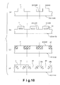
- diagrams (b) to (d) of Figure 10 show a plurality of modified structures of the shorting rotor member 1B or 101B with the circumferential direction extended into a generally straight line
- a diagram (a) of Figure 10 illustrates the shorting rotor member 1B or 101B of the embodiment shown in Figure 1 or Figure 8.
- the shorting rotor member 1B or 101B can be made with any one of the configurations described below.
- the diagram (b) of Figure 10 shows the shorting rotor member 1B (101B) provided with a plurality of permanent magnets 20 arranged inside the protruding poles 9 (109).
- the permanent magnets 20 are arranged such that the magnetization direction of the permanent magnets 20 is the same as the protruding direction of the protruding poles 9 (109), i.e., perpendicular to the radial gap surface or the axial gap surface.
- the shorting rotor member 1B (101B) can be selectively driven independently from the drive rotor member 1A (101A) using the composite electrical current.
- the diagram (c) of Figure 10 shows the shorting rotor member 1B (101B) in which the recess portions 10 (110) between the protruding poles 9 (109) are filled with a non-magnetic material such as a resin 17 or other non-magnetic material with a large magnetic resistance. Since the resin 17 is disposed between the protruding poles 9 (109) as shown in the diagram (c) of Figure 10, the shorting rotor member 1B (101B) can establish a short-circuit in the magnetic flux of the permanent magnets 8 (108) in the same manner as in the first and second embodiments shown in the diagram (a) of Figure 10.
- a non-magnetic material such as a resin 17 or other non-magnetic material with a large magnetic resistance. Since the resin 17 is disposed between the protruding poles 9 (109) as shown in the diagram (c) of Figure 10, the shorting rotor member 1B (101B) can establish a short-circuit in the magnetic flux of the permanent magnets 8 (108) in the
- the diagram (d) of Figure 10 shows the shorting rotor member 101B in which the protruding poles 9 (109) and the recess portions 10 (110) illustrated in the diagram (a) are replaced with a structure using a plurality of permanent magnets 18a and 18b.
- the permanent magnets 18a and 18b are embedded inside the shorting rotor member 1B (101B) instead of having the protruding poles 9 (109) and the recess portions 10 (110) arranged alternately.
- the shorting rotor member 101B includes a plurality of front yolk sections 19 made of a magnetic material.
- the front yolk sections 19 are provided in circumferential positions corresponding to the protruding poles 9 (109) of the structures shown in the diagrams (a) to (c) of Figure 10.
- each of the front yolk sections 19 includes a plurality of pairs of left and right permanent magnets 18a and 18b.
- each of the front yolk sections 19 is made of a magnetic material and is bordered by the permanent magnets 18a and 18b and the radial gap surface (or axial gap surface).
- both of the permanent magnets 18a and 18b of each pair are magnetized to the same polarity.
- the front yolk sections 19 are aligned in the circumferential direction with one permanent magnet 8 (108) of each of the first and second drive rotor sections 1A 1 and 1A 2 (101A 1 and 101A 2 ). Therefore, the front yolk sections 19 do not establish a short-circuit in the magnetic flux of the adjacent permanent magnets 8 (108).
- the rotational speed of the rotor unit 1 (101 and 121) is high or when other prescribed conditions exist, the shorting rotor member 101B of the diagram (d) of Figure 10 is driven to rotate with respect to the drive rotor member 1A (101A). Therefore, the front yolk sections 19 straddle (partially overlap) two circumferentially adjacent permanent magnets 8 (108) (which have opposite polarities).
- the composite electrical current is supplied to the coils 6 (106) of the stator 3 (103), and the first magnetic circuit ⁇ 1 ( Figure 1(b)) is formed using the first current component of the composite electrical circuit and the second magnetic circuit ⁇ 2 ( Figure 1(c)) is formed using the second current component of the composite electrical current.
- the first magnetic circuit ⁇ 1 is used to drive the drive rotor member 1A (101A) and the second magnetic circuit ⁇ 2 is used to drive the shorting rotor member 1B (101B) to switch between the shorted state and the normal state.
- the permanent magnets 8 (108) can be shorted using the conventional electromagnets (formed by the coils 6 (106) of the stator 3 (103)) without the need for a separate actuator or other operating mechanism. Consequently, the size of the motor/generator can be suppressed.
- the shorting rotor member 1B (101B) independently of the rotational speed of the rotor unit 1 (101 and 121) by controlling the second current component of the composite electrical current.
- the magnetic flux of the permanent magnets 8 (108) can be shorted during any operating state regardless of the rotational speed of the rotor unit 1 (101 and 121). Accordingly, the induced voltage can be suppressed any time it is necessary to do so, such as when there is a problem with the battery or when the temperature of a device provided in the electric circuit is abnormally high.
- the shorting rotor member B In addition to operating the shorting rotor member 1B (101B) independently of the rotational speed of the rotor unit 1 (101 and 121), the shorting rotor member B can be operated to vary the amount of shorted magnetic flux. As a result, as shown in Figure 11, the operating region can be expanded comparing to the comparative examples of the motor/generator.
- the drive rotor member 1A (101A) has the first drive rotor section 1A 1 (101A 1 ) and the second drive rotor section 1A 2 (101A 2 ).
- the first and second drive rotor sections 1A 1 and 1A 2 (101A 1 and 101A 2 ) are provided on both sides of the shorting rotor member B, respectively, and each of the first and second drive rotor sections 1A 1 and 1A 2 (101A 1 and 101A 2 ) has a surface that faces the radial gap 4 or the axial gap 104 that lies between the drive rotor member 1A (101A) and the stator 3 (103).
- the axial center of the drive rotor member would be offset from the axial center of the stator 3 (the tooth sections 5). Consequently, the attractive and repelling forces exerted against the drive rotor member by the stator 3 would cause an axial force to act on the drive rotor member. Therefore, an unnecessary force acts on the rotary shaft 2 of the rotor unit 1.
- the first and second drive rotor sections 1A 1 and 1A 2 are arranged on both axial sides of the shorting rotor member 1B, respectively. Thus, the axial forces are counterbalanced and an unnecessary force does not act on the rotary shaft 2.
- the radial center of the drive rotor member would be offset from the radial center of the stator 103 (the tooth sections 105). Consequently, the attractive and repelling forces exerted against the drive rotor member by the stator 103 would cause a radial force to act on the drive rotor member. Therefore, an unnecessary force acts on the rotary shaft 2 of the rotor unit 101.
- the first and second drive rotor sections 101A 1 and 101A 2 are arranged on both radial sides of the shorting rotor member 101B, respectively. Thus, the radial forces are counterbalanced and an unnecessary force does not act on the rotary shaft 2.
- any of the configurations shown in the diagrams (a) to (d) of Figure 10 can be used for the shorting rotor member 1B (101B), which serves as a permanent magnet shorting mechanism.
- the present invention is not limited to establishing a short-circuit in the magnetic flux of the permanent magnets 8 (108) when the rotational speed of the rotor unit 1 (101 and 121) is high (e.g., the rotational speed is greater than the prescribed value).
- the magnetic flux of the permanent magnets 8 (108) can be shorted when there is a problem with a battery (not shown) used to supply electric power to the coils 6 (106) of the electromagnets or when there is a problem with an electric circuit that connects the battery to the coils 6 (106) of the electromagnets.
- the battery can be protected and such electric circuit components as an inverter or a semiconductor device inside the inverter can be protected by establishing a short-circuit in the magnetic flux of the permanent magnets 8 (108).
- the permanent magnets 8 (108) arranged circumferentially to be centered around the rotary shaft 2 are provided on the rotor unit 1 (101 and 121).
- the shorting rotor member 1B (101B) mounted to the rotor unit 1 (101 and 121) is arranged as the annular member that is made of a magnetic material and provided with a plurality of the protruding poles 9 (109).
- the shorting rotor member 1B (101B) can be rotated to a position where the protruding poles 9 (109) function to establish a short-circuit in the magnetic flux of the adjacent permanent magnets 8 (108).
- the shorting rotor member 1B (101B) can be selectively operated using torque generated by the motor/generator.
- the motor/generator in accordance with the embodiments of the present invention can suppress the induced voltage while remaining approximately the same size as a conventional motor/generator.
- the motor/generator has a radial gap structure in which the rotor unit 1 and the stator 3 are arranged radially relative to each other to have the radial gap 4 between the rotor unit 1 and the stator 3.
- the permanent magnets 8 are arranged on the radial gap surface 7a of the rotor unit 1, i.e., the surface of the rotor unit 1 that faces the stator 3 across the radial gap 4.
- the permanent magnets 8 are arranged circumferentially such that the polarities of any two circumferentially adjacent permanent magnets 8 are opposite each other.
- the shorting rotor member 1B having the circumferentially arranged protruding poles 9 is mounted to the rotor unit 1 such that the protruding poles 9 are arranged at the radial gap surface 7b of the rotor unit 1.
- the motor/generator has an axial gap structure in which the rotor units 101 and 121 and the stator 103 are arranged along the direction of the rotor rotational axis O to have the axial gaps 104 between the rotor units 101 and 121 and the stator 103.
- the permanent magnets 108 are arranged on an axial gap surface of the rotor unit 101 (121), i.e., the surface of the rotor unit 101 (121) that faces the stator 103 across the axial gap 104.
- the permanent magnets 108 are arranged circumferentially such that the polarities of any two circumferentially adjacent permanent magnets 108 are opposite each other.
- the shorting rotor member B having the circumferentially arranged protruding poles 109 is mounted to the rotor unit 101 such that the protruding poles 109 are arranged at the axial gap surface of the rotor unit 101.
- the amount of relative rotation between the shorting rotor member 11B and the drive rotor member 11A can be limited to within the prescribed amount by making the internal circumference of the shorting rotor member 11B and the external circumference of the recessed section 12' of the drive rotor member 11A each have a polygonal shape and providing the gap 14 therebetween.
- the shorting rotor member 11B is mounted to the drive rotor member 11A such that the shorting rotor member 11B can rotate relative to the drive rotor member 11A and the elastic members 15 are disposed between the shorting rotor member 11B and the drive rotor member 11A. Consequently, the shorting rotor member 11B cannot rotate limitlessly relative to the drive rotor member 11A.
- the drive force imparted to the shorting rotor member 11B when the shorting rotor member 11B is driven can be transferred through the elastic members 15 to the rotary shaft 2 and outputted, thereby enabling the drive force to be used without waste.
- the spring forces of the elastic members 15 can be set such that the relative position of the shorting rotor member 11B is aligned with the permanent magnets 8 as shown in Figure 5 during the normal state and such that the shorting member 11B rotates against the spring forces of the elastic member 15 to the offset state (shorted state (e.g., the state shown in Figure 6) when the rotational speed of the rotor unit 11 is high.
- the shorting rotor member 11B can be returned automatically to the normal position shown in Figure 5, i.e., the position where the protruding poles 9 are aligned with (not straddling) the permanent magnets 8, by simply terminating the driving force exerted against the shorting rotor member 11B because the spring forces of the elastic members 15 act to return the shorting rotor member B to said normal position.
- the shorting rotor member 11B does not need to be driven back to the normal state and the return process can be simplified.
- the present invention is not limited to the embodiments described herein and various modifications can be made without departing from the scope of the invention.
- the embodiments shown in Figures 1 and 8 can be modified from having the drive rotor member 1A (101A) with the first and second drive rotor sections 1A 1 and 1A 2 (101A 1 and 101A 2 ) arranged on both sides of the shorting rotor member 1B (101B) to having one drive rotor member arranged on one side of the shorting rotor member 1B(101B).
- the stopper mechanism for limiting the amount of the relative rotation between the drive rotor member 11A and the shorting rotor member 11B is not limited to the stopper 50 as shown in Figures 7(a) and 7(b), which includes the recessed section 12' of the drive rotor member 11A having the polygonal external circumference and the shorting rotor member 11B having the polygonal internal circumference. Rather, any structure or mechanism for limiting the amount of relative rotation between the drive rotor member 1A (101A) and the shorting rotor member 1B (101B) can be used as the stopper of the present invention.
- the term “comprising” and its derivatives, as used herein, are intended to be open ended terms that specify the presence of the stated features, elements, components, groups, integers, and/or steps, but do not exclude the presence of other unstated features, elements, components, groups, integers and/or steps.
- the foregoing also applies to words having similar meanings such as the terms, “including”, “having” and their derivatives.
- the terms “part,” “section,” “portion,” “member” or “element” when used in the singular can have the dual meaning of a single part or a plurality of parts. Accordingly, these terms, as utilized to describe the present invention should be interpreted relative to a vehicle equipped with the present invention.
- the terms of degree such as “substantially”, “about” and “approximately” as used herein mean a reasonable amount of deviation of the modified term such that the end result is not significantly changed.
Landscapes
- Engineering & Computer Science (AREA)
- Power Engineering (AREA)
- Permanent Field Magnets Of Synchronous Machinery (AREA)
- Permanent Magnet Type Synchronous Machine (AREA)
- Iron Core Of Rotating Electric Machines (AREA)
Applications Claiming Priority (2)
| Application Number | Priority Date | Filing Date | Title |
|---|---|---|---|
| JP2006037075 | 2006-02-14 | ||
| JP2007029664A JP5141030B2 (ja) | 2006-02-14 | 2007-02-08 | 回転電機 |
Publications (2)
| Publication Number | Publication Date |
|---|---|
| EP1819030A1 true EP1819030A1 (fr) | 2007-08-15 |
| EP1819030B1 EP1819030B1 (fr) | 2013-04-10 |
Family
ID=38709908
Family Applications (1)
| Application Number | Title | Priority Date | Filing Date |
|---|---|---|---|
| EP07102145.5A Active EP1819030B1 (fr) | 2006-02-14 | 2007-02-12 | Moteur/générateur |
Country Status (4)
| Country | Link |
|---|---|
| US (1) | US7671494B2 (fr) |
| EP (1) | EP1819030B1 (fr) |
| JP (1) | JP5141030B2 (fr) |
| CN (1) | CN101022226B (fr) |
Cited By (2)
| Publication number | Priority date | Publication date | Assignee | Title |
|---|---|---|---|---|
| RU2545525C1 (ru) * | 2013-10-16 | 2015-04-10 | Олег Фёдорович Меньших | Бесколлекторный мотор-генератор постоянного тока |
| RU2751098C1 (ru) * | 2020-12-18 | 2021-07-08 | Николай Владимирович Конев | Бесколлекторная электромашина постоянного тока |
Families Citing this family (17)
| Publication number | Priority date | Publication date | Assignee | Title |
|---|---|---|---|---|
| CN101227136A (zh) * | 2007-01-16 | 2008-07-23 | 林冈嵚 | 独立自主自由式积复激自动环聚同步磁能动力发电机 |
| EP3540915B1 (fr) * | 2007-11-15 | 2022-05-11 | Mitsubishi Electric Corporation | Machine électrique rotative de type à aimant permanent et dispositif à direction assistée électrique |
| GB2457342B (en) * | 2008-02-15 | 2013-02-13 | Power Ramps Ltd | Improvements in and relating to apparatus for converting kinetic energy |
| US8350502B2 (en) * | 2009-07-09 | 2013-01-08 | Rabal Clifford R | Electromagnetic motor |
| US9018891B2 (en) * | 2009-07-09 | 2015-04-28 | Clifford R. Rabal | Direct current brushless motor |
| US20110095636A1 (en) * | 2009-10-27 | 2011-04-28 | Chiu-Fa Lee | Magnetic force based automatic power generation device |
| ITMI20110378A1 (it) * | 2011-03-10 | 2012-09-11 | Wilic Sarl | Macchina elettrica rotante per aerogeneratore |
| CN103580411A (zh) * | 2012-08-10 | 2014-02-12 | 杨荷 | 一种永磁无刷自适应变速驱动电机 |
| CN103633799B (zh) * | 2012-08-29 | 2017-11-03 | 杨世国 | 一种自动连续变速永磁无刷轮毂电机 |
| JP6131691B2 (ja) * | 2013-04-17 | 2017-05-24 | 株式会社ジェイテクト | 回転電機 |
| CN104917315B (zh) * | 2015-06-17 | 2017-09-19 | 重庆西伟迪磁电动力科技有限公司 | 一种具有多离心片组合式调速器的永磁无刷电机 |
| US10186917B2 (en) * | 2016-05-24 | 2019-01-22 | Unison Industries, Llc | Rotor assembly for a power generation system |
| CN106100271B (zh) * | 2016-08-04 | 2019-02-19 | 浙江大学 | 轴径向磁通的调磁电机 |
| GB201709455D0 (en) * | 2017-06-14 | 2017-07-26 | Rolls Royce Plc | Electrical machine |
| LU100555B1 (en) * | 2017-12-13 | 2019-06-28 | Luxembourg Inst Science & Tech List | Compact halbach electrical generator with coils arranged circumferentially |
| JP2020174492A (ja) * | 2019-04-12 | 2020-10-22 | パナソニックIpマネジメント株式会社 | モータ |
| CN114389422B (zh) | 2022-01-14 | 2023-12-22 | 无锡星驱科技有限公司 | 一种凸极式混合励磁电机 |
Citations (9)
| Publication number | Priority date | Publication date | Assignee | Title |
|---|---|---|---|---|
| EP0447257A2 (fr) * | 1990-03-16 | 1991-09-18 | Satake Engineering Co., Ltd. | Moteur synchrone ayant deux stators |
| JPH07143694A (ja) * | 1993-11-11 | 1995-06-02 | Toyota Motor Corp | 同期機のロータ構造および同期型モータ |
| US6049152A (en) | 1998-03-25 | 2000-04-11 | Nissan Motor Co., Ltd. | Motor/generator |
| JP2001119875A (ja) * | 1999-10-14 | 2001-04-27 | Denso Corp | 同期機及びそれを用いた電気自動車用回転電機 |
| JP2001314053A (ja) | 2000-05-01 | 2001-11-09 | Denso Corp | 永久磁石界磁極型回転電機 |
| US20030090167A1 (en) | 1999-10-14 | 2003-05-15 | Denso Corporation | Rotary electric machine for electric vehicle |
| US20030102756A1 (en) * | 2001-10-24 | 2003-06-05 | Denso Corporation | High electrical and mechanical response structure of motor-generator |
| US20060082238A1 (en) * | 2001-11-27 | 2006-04-20 | Denso Corporation | Brushless rotary electric machine having tandem rotary cores |
| US20060192518A1 (en) * | 2005-02-25 | 2006-08-31 | Caterpillar Inc. | Multi-motor switched reluctance traction system |
Family Cites Families (7)
| Publication number | Priority date | Publication date | Assignee | Title |
|---|---|---|---|---|
| JPH0993846A (ja) * | 1995-07-14 | 1997-04-04 | Meidensha Corp | 永久磁石式同期電動機 |
| JPH09308200A (ja) * | 1996-05-13 | 1997-11-28 | Toshiba Corp | 永久磁石式回転電機 |
| JP3480300B2 (ja) * | 1998-03-25 | 2003-12-15 | 日産自動車株式会社 | 回転電機 |
| JP3468726B2 (ja) * | 1999-09-01 | 2003-11-17 | 株式会社日立製作所 | ハイブリッド車及び回転電機 |
| JP4269544B2 (ja) * | 2000-09-14 | 2009-05-27 | 株式会社デンソー | 複数ロータ型同期機 |
| JP3671884B2 (ja) * | 2001-08-30 | 2005-07-13 | 日産自動車株式会社 | 回転電機 |
| JP4320552B2 (ja) * | 2003-02-07 | 2009-08-26 | 株式会社デンソー | 磁束量可変磁石型ロータ |
-
2007
- 2007-02-08 JP JP2007029664A patent/JP5141030B2/ja active Active
- 2007-02-12 EP EP07102145.5A patent/EP1819030B1/fr active Active
- 2007-02-12 US US11/673,641 patent/US7671494B2/en active Active
- 2007-02-14 CN CN200710005370.4A patent/CN101022226B/zh active Active
Patent Citations (9)
| Publication number | Priority date | Publication date | Assignee | Title |
|---|---|---|---|---|
| EP0447257A2 (fr) * | 1990-03-16 | 1991-09-18 | Satake Engineering Co., Ltd. | Moteur synchrone ayant deux stators |
| JPH07143694A (ja) * | 1993-11-11 | 1995-06-02 | Toyota Motor Corp | 同期機のロータ構造および同期型モータ |
| US6049152A (en) | 1998-03-25 | 2000-04-11 | Nissan Motor Co., Ltd. | Motor/generator |
| JP2001119875A (ja) * | 1999-10-14 | 2001-04-27 | Denso Corp | 同期機及びそれを用いた電気自動車用回転電機 |
| US20030090167A1 (en) | 1999-10-14 | 2003-05-15 | Denso Corporation | Rotary electric machine for electric vehicle |
| JP2001314053A (ja) | 2000-05-01 | 2001-11-09 | Denso Corp | 永久磁石界磁極型回転電機 |
| US20030102756A1 (en) * | 2001-10-24 | 2003-06-05 | Denso Corporation | High electrical and mechanical response structure of motor-generator |
| US20060082238A1 (en) * | 2001-11-27 | 2006-04-20 | Denso Corporation | Brushless rotary electric machine having tandem rotary cores |
| US20060192518A1 (en) * | 2005-02-25 | 2006-08-31 | Caterpillar Inc. | Multi-motor switched reluctance traction system |
Cited By (2)
| Publication number | Priority date | Publication date | Assignee | Title |
|---|---|---|---|---|
| RU2545525C1 (ru) * | 2013-10-16 | 2015-04-10 | Олег Фёдорович Меньших | Бесколлекторный мотор-генератор постоянного тока |
| RU2751098C1 (ru) * | 2020-12-18 | 2021-07-08 | Николай Владимирович Конев | Бесколлекторная электромашина постоянного тока |
Also Published As
| Publication number | Publication date |
|---|---|
| US7671494B2 (en) | 2010-03-02 |
| US20070188036A1 (en) | 2007-08-16 |
| CN101022226A (zh) | 2007-08-22 |
| JP2007252184A (ja) | 2007-09-27 |
| JP5141030B2 (ja) | 2013-02-13 |
| EP1819030B1 (fr) | 2013-04-10 |
| CN101022226B (zh) | 2010-05-19 |
Similar Documents
| Publication | Publication Date | Title |
|---|---|---|
| EP1819030B1 (fr) | Moteur/générateur | |
| US8294318B2 (en) | Electric motor and rotor for rotating electric machine | |
| US7960888B2 (en) | Electric motor with field weakening | |
| EP3300231B1 (fr) | Machine électrique | |
| US7884518B2 (en) | Electrical synchronous machine | |
| US20030201681A1 (en) | Brushless motor and electric power steering apparatus equipped with the brushless motor | |
| US7750527B2 (en) | Motor/generator | |
| EP2234251B1 (fr) | Actionneur electromagnetique oscillant a trois positions stables | |
| CN103178673A (zh) | 旋转电机 | |
| EP2696485A2 (fr) | Machine électrique rotative | |
| JPWO2017195263A1 (ja) | 永久磁石型モータ | |
| EP1835600A2 (fr) | Moteur/générateur | |
| US20240079921A1 (en) | Motor generator | |
| JP2014220884A (ja) | 回転電機 | |
| JP4408093B2 (ja) | 回転電機 | |
| JP4890056B2 (ja) | 電動機 | |
| JP5638923B2 (ja) | 永久磁石を用いた回転装置 | |
| EP2609673B1 (fr) | Moteur électrique | |
| JP2021175341A (ja) | モータ | |
| US12301058B2 (en) | Rotor having end magnet fixed by fixing member | |
| JP5891428B2 (ja) | アクチュエータ装置 | |
| JP2024007087A (ja) | モータ | |
| JP2007259525A (ja) | 永久磁石同期電動機/発電機 | |
| JPH07213040A (ja) | 3相ブラシレスモータ | |
| CN120979106A (zh) | 旋转电机 |
Legal Events
| Date | Code | Title | Description |
|---|---|---|---|
| PUAI | Public reference made under article 153(3) epc to a published international application that has entered the european phase |
Free format text: ORIGINAL CODE: 0009012 |
|
| AK | Designated contracting states |
Kind code of ref document: A1 Designated state(s): AT BE BG CH CY CZ DE DK EE ES FI FR GB GR HU IE IS IT LI LT LU LV MC NL PL PT RO SE SI SK TR |
|
| AX | Request for extension of the european patent |
Extension state: AL BA HR MK YU |
|
| 17P | Request for examination filed |
Effective date: 20080215 |
|
| 17Q | First examination report despatched |
Effective date: 20080314 |
|
| AKX | Designation fees paid |
Designated state(s): DE FR GB |
|
| GRAP | Despatch of communication of intention to grant a patent |
Free format text: ORIGINAL CODE: EPIDOSNIGR1 |
|
| RIN1 | Information on inventor provided before grant (corrected) |
Inventor name: SHIBUKAWA, YUICHI |
|
| GRAS | Grant fee paid |
Free format text: ORIGINAL CODE: EPIDOSNIGR3 |
|
| GRAA | (expected) grant |
Free format text: ORIGINAL CODE: 0009210 |
|
| AK | Designated contracting states |
Kind code of ref document: B1 Designated state(s): DE FR GB |
|
| REG | Reference to a national code |
Ref country code: GB Ref legal event code: FG4D |
|
| REG | Reference to a national code |
Ref country code: DE Ref legal event code: R096 Ref document number: 602007029595 Country of ref document: DE Effective date: 20130606 |
|
| PLBE | No opposition filed within time limit |
Free format text: ORIGINAL CODE: 0009261 |
|
| STAA | Information on the status of an ep patent application or granted ep patent |
Free format text: STATUS: NO OPPOSITION FILED WITHIN TIME LIMIT |
|
| 26N | No opposition filed |
Effective date: 20140113 |
|
| REG | Reference to a national code |
Ref country code: DE Ref legal event code: R097 Ref document number: 602007029595 Country of ref document: DE Effective date: 20140113 |
|
| REG | Reference to a national code |
Ref country code: FR Ref legal event code: PLFP Year of fee payment: 10 |
|
| REG | Reference to a national code |
Ref country code: FR Ref legal event code: PLFP Year of fee payment: 11 |
|
| REG | Reference to a national code |
Ref country code: FR Ref legal event code: PLFP Year of fee payment: 12 |
|
| REG | Reference to a national code |
Ref country code: FR Ref legal event code: PLFP Year of fee payment: 17 |
|
| PGFP | Annual fee paid to national office [announced via postgrant information from national office to epo] |
Ref country code: GB Payment date: 20260122 Year of fee payment: 20 |
|
| PGFP | Annual fee paid to national office [announced via postgrant information from national office to epo] |
Ref country code: DE Payment date: 20260121 Year of fee payment: 20 |
|
| PGFP | Annual fee paid to national office [announced via postgrant information from national office to epo] |
Ref country code: FR Payment date: 20260121 Year of fee payment: 20 |