EP1819977B1 - Fours de traitement de ceramiques et procedes d'utilisation de tels fours - Google Patents
Fours de traitement de ceramiques et procedes d'utilisation de tels fours Download PDFInfo
- Publication number
- EP1819977B1 EP1819977B1 EP05849680A EP05849680A EP1819977B1 EP 1819977 B1 EP1819977 B1 EP 1819977B1 EP 05849680 A EP05849680 A EP 05849680A EP 05849680 A EP05849680 A EP 05849680A EP 1819977 B1 EP1819977 B1 EP 1819977B1
- Authority
- EP
- European Patent Office
- Prior art keywords
- kiln
- radiant barrier
- airflow passageway
- inner body
- outer body
- Prior art date
- Legal status (The legal status is an assumption and is not a legal conclusion. Google has not performed a legal analysis and makes no representation as to the accuracy of the status listed.)
- Expired - Lifetime
Links
Images


Classifications
-
- F—MECHANICAL ENGINEERING; LIGHTING; HEATING; WEAPONS; BLASTING
- F27—FURNACES; KILNS; OVENS; RETORTS
- F27D—DETAILS OR ACCESSORIES OF FURNACES, KILNS, OVENS OR RETORTS, IN SO FAR AS THEY ARE OF KINDS OCCURRING IN MORE THAN ONE KIND OF FURNACE
- F27D9/00—Cooling of furnaces or of charges therein
-
- F—MECHANICAL ENGINEERING; LIGHTING; HEATING; WEAPONS; BLASTING
- F27—FURNACES; KILNS; OVENS; RETORTS
- F27B—FURNACES, KILNS, OVENS OR RETORTS IN GENERAL; OPEN SINTERING OR LIKE APPARATUS
- F27B17/00—Furnaces of a kind not covered by any of groups F27B1/00 - F27B15/00
- F27B17/0016—Chamber type furnaces
- F27B17/0041—Chamber type furnaces specially adapted for burning bricks or pottery
- F27B17/005—Chamber type furnaces specially adapted for burning bricks or pottery with cylindrical chambers
-
- F—MECHANICAL ENGINEERING; LIGHTING; HEATING; WEAPONS; BLASTING
- F27—FURNACES; KILNS; OVENS; RETORTS
- F27B—FURNACES, KILNS, OVENS OR RETORTS IN GENERAL; OPEN SINTERING OR LIKE APPARATUS
- F27B5/00—Muffle furnaces; Retort furnaces; Other furnaces in which the charge is held completely isolated
- F27B5/06—Details, accessories or equipment specially adapted for furnaces of these types
- F27B5/16—Arrangements of air or gas supply devices
-
- F—MECHANICAL ENGINEERING; LIGHTING; HEATING; WEAPONS; BLASTING
- F27—FURNACES; KILNS; OVENS; RETORTS
- F27D—DETAILS OR ACCESSORIES OF FURNACES, KILNS, OVENS OR RETORTS, IN SO FAR AS THEY ARE OF KINDS OCCURRING IN MORE THAN ONE KIND OF FURNACE
- F27D1/00—Casings; Linings; Walls; Roofs
- F27D1/18—Door frames; Doors, lids or removable covers
-
- F—MECHANICAL ENGINEERING; LIGHTING; HEATING; WEAPONS; BLASTING
- F27—FURNACES; KILNS; OVENS; RETORTS
- F27D—DETAILS OR ACCESSORIES OF FURNACES, KILNS, OVENS OR RETORTS, IN SO FAR AS THEY ARE OF KINDS OCCURRING IN MORE THAN ONE KIND OF FURNACE
- F27D9/00—Cooling of furnaces or of charges therein
- F27D2009/0002—Cooling of furnaces
- F27D2009/0005—Cooling of furnaces the cooling medium being a gas
-
- Y—GENERAL TAGGING OF NEW TECHNOLOGICAL DEVELOPMENTS; GENERAL TAGGING OF CROSS-SECTIONAL TECHNOLOGIES SPANNING OVER SEVERAL SECTIONS OF THE IPC; TECHNICAL SUBJECTS COVERED BY FORMER USPC CROSS-REFERENCE ART COLLECTIONS [XRACs] AND DIGESTS
- Y10—TECHNICAL SUBJECTS COVERED BY FORMER USPC
- Y10T—TECHNICAL SUBJECTS COVERED BY FORMER US CLASSIFICATION
- Y10T29/00—Metal working
- Y10T29/49—Method of mechanical manufacture
- Y10T29/49826—Assembling or joining
Definitions
- the present invention is directed generally toward kilns for processing ceramics and, more particularly, to portable kilns for use in the home environment:
- Kilns as described in DE 29600841U1 , GB 1466999A1 and DE7704066U1 can be used to harden, bum, and/or dry a number of different materials in one common application, for example.
- kilns are used in the production of ceramics.
- This process can include chemically refining clay objects by heating them until a crystalline matrix of silica and alumina forms, thus making the resulting ceramic articles hard and durable.
- this process can take a significant amount of time.
- the temperature of an internal processing chamber is raised to a relatively high temperature (e.g., 982 ⁇ 2°C (1800°F), maintained at that temperature for a given period of time to adequately heat the clay object until the clay develops the desired properties, and then cooled relatively quickly so that the ceramic workpieces can be retrieved from the processing chamber and the kiln can be used to process another workpiece.
- a relatively high temperature e.g. 982 ⁇ 2°C (1800°F
- conventional kilns typically Include relatively thick insulating sidewalls and extensive cooling systems. As a result these kilns are large and cumbersome, relatively expensive, and generally unsuitable for home or personal use.
- the exterior surfaces of such kilns can still become relatively hot during operation, thus making the kilns undesirable for in-home or personal use.
- a kiln configured in accordance with one embodiment of the invention includes an inner body configured to hold one or more ceramic workpieces for processing The kiln also includes an outer body at least partially surrounding the inner body and spaced apart from the inner body to define an airflow passageway therebetween.
- the airflow passageway includes an inlet proximate to an upper portion of the outer body and an outlet proximate to a lower portion of the outer body
- the kiln further inciudes an air mover positioned to move air through the airflow passageway from the inlet toward the outlet
- the kiln can additionally include a lid assembly pivotably coupled to the outer body and configured to sealably close against at least the inner body.
- a kiln configured in accordance with the invention includes an inner body configured to hold one or more ceramic workpieces for processing, and an outer body spaced apart from the inner body to define an airflow passageway therebetween.
- the airflow passageway includes an inlet proximate to an upper portion of the outer body and an outlet proximate to a lower portion of the outer body
- the kiln can also include a lid assembly operably coupled to the outer body and configured to sealably close against at least the inner body.
- the kiln further includes a radiant barrier positioned in the airflow passageway between the inner body and the outer body, and a fan positioned proximate to the lower portion of the outer body. The fan is positioned to move air through the airflow passageway from the inlet toward the outlet to cool the inner body during processing of the ceramic workpieces.
- a method for processing ceramics includes placing a ceramic workpiece into a processing chamber of a kiln and increasing the temperature in the processing chamber to process the ceramic workpiece.
- the method also includes flowing air from an inlet positioned proximate to an upper portion of the kiln through a passageway extending at least partially around the processing chamber to maintain the temperature of an exterior portion of the kiln at or below a preset temperature.
- the method further includes reflecting at least a portion of the heat generated by the processing chamber back toward the inner body using a radiant barrier positioned in the airflow passageway.
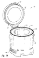
- Figures 1A and 1B are isometric views of a kiln configured in accordance with an embodiment of the invention
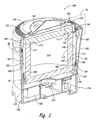
- Figure 2 is an isometric cross-sectional view of the kiln of Figures 1A and 1B .
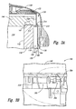
- Figure 3A is an enlarged, side cross-sectional view taken from the area 3A of Figure 2 illustrating several aspects of the invention.
- Figure 3B is an enlarged, side cross-sectional view taken from the area 3B of Figure 2 illustrating other aspects of the invention
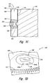
- Figure 3C is an enlarged, side cross-sectional view taken from the area 3C of Figure 2 illustrating further aspects of the invention
- Figure 3D is an enlarged, isometric view taken from the area 3D of Figure 1B illustrating yet another aspect of the invention.
- Figure 4A is a side view and Figure 4B is a bottom isometric view of the kiln of Figures 1A-3D and a kiln transport assembly configured in accordance with an embodiment of the invention.
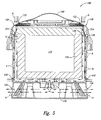
- Figure 5 is a side cross-sectional view of the Kiln of Figures 1A-3D illustrating various aspects of several embodiments for cooling the kiln during operation
- Figures 1A and 1B are isometric views of a kiln 100 configured in accordance with an embodiment of the invention
- the kiln 100 can include an inner body 110 configured to hold one or more ceramic workpieces (not shown), and an outer body 120 at least partially surrounding the inner body 110.
- the outer body 120 is spaced apart from the inner body 110 to define an airflow passageway 130 therebetween
- the kiln 100 can further include a lid assembly 140 pivotably coupled to the outer body 120.
- the lid assembly 140 can be configured to sealably close against the inner body 110 and, in at least several embodiments, the outer body 120.
- the lid assembly 140 is illustrated in an open position to provide access to a processing chamber 114.
- the lid assembly 140 is sealably closed against the inner body 110 and at least a portion of the outer body 120 for workpiece processing.
- the kiln 100 includes an air inlet 132 in the lid assembly 140 and an air outlet 134 in the outer body 120.
- the Inlet 132 and outlet 134 are in fluid communication with the airflow passageway 130 ( Figure 1A ).
- the kiln 100 further includes an air mover configured to move ambient air through the airflow passageway 130 from the inlet 132 toward the outlet 134 to maintain the surface temperature of the outer body 120 at or below a preset temperature during operation of the kiln 100
- the surface temperature of the outer body 120 can remain cool to the touch, while the processing chamber 114 is heated to over 982 ⁇ 2°C for workpiece processing.
- Various features of several embodiments of the system for cooling the inner body 110 are described in greater detail below with reference to Figures 2-5 .
- FIG 2 is an isometric cross-sectional view of the kiln 100 of Figures 1A and 1B .
- the inner body 110 includes an inner wall 112 defining the processing chamber 114 for ceramic workpieces (not shown).
- the inner body 110 further includes an outer wall 116 that faces the outer body 120.
- the inner body 110 can include a refractory material that is configured to withstand the high temperatures necessary to process the ceramic workpiece and the drastic changes in temperature throughout the processing cycle.
- the thickness of the inner body 110 i.e., the distance between the inner wall 112 and the outer wall 116) can vary depending on the desired operational parameters for the kiln 100 and/or the material used to form the inner body 110.
- the lid assembly 140 further includes an inner body lid portion 146 configured to releasably engage or otherwise mate with the inner body 110 to sealably close the processing chamber 114.
- the inner body lid portion 146 can include a first chamfered portion 147 configured to mate with a second chamfered portion 117 of the inner body 110 to seal the processing chamber 114 when the lid assembly 140 is closed (as illustrated in Figure 2 ).
- One advantage of the relatively large surface area of the interface between the sidewall of the inner body 110 and the inner body lid portion 146 is that the chamfered interface can minimize heat loss from the processing chamber 114 during operation as compared with processing chambers that include non-chamfered interfaces.
- the inner body lid portion 146 carried by the lid assembly 140 can be slightly adjustable (e.g., it can "float” or move horizontally and/or vertically) relative to the lid assembly 140 and the inner body 110, thereby allowing the first chamfered interface portion 147 of the inner body lid portion 146 to more accurately and tightly seat against the second chamfered interface portion 117 of the inner body 110.
- the kiln 100 includes a first radiant barrier 160 positioned in the airflow passageway 130 between the inner body 110 and the outer body 120, and a second radiant barrier 168 carried by the lid assembly 140.
- the first radiant barrier 160 can include a first side 162 facing the outer wall 116 of the inner body 110 and a second side 164 facing the outer body 120.
- the first radiant barrier 160 defines (a) a first portion 136 of the airflow passageway 130 between the inner body 110 and the first side 162 of the first radiant barrier 160, and (b) a second portion 138 of the airflow passageway 130 between the second side 164 of the first radiant barrier 160 and the outer body 120. Further details regarding the first and second portions 136 and 138 of the airflow passageway 130 are described below with respect to Figure 5 .
- the second radiant barrier 168 is spaced apart from the inner body lid portion 146.
- the first side 162 of the first radiant barrier 160 and the lower side of the second radiant barrier 168 facing the inner body lid portion 146 can each include a polished, highly reflective surface.
- the first radiant barrier 160 can also include a plurality of fins 166 projecting from the first side 162 of the first radiant barrier 160 toward the outer wall 116 of the inner body 110. The fins 166 are positioned to create an area of low pressure within the first portion 136 of the airflow passageway 130 to help increase the flow of air within this portion of the airflow passageway 130.
- the first and second radiant barriers 160 and 168 can include different features and/or have other arrangements depending on a number of different factors including manufacturing cost, operating temperatures, etc.
- the kiln 100 includes an air mover 170 (e.g., a fan) positioned to move air through the airflow passageway 130 from the inlet 132 toward the outlet 134.
- the air mover 170 is located proximate to a lower portion of the kiln 100 in communication with the airflow passageway 130. In other embodiments, however, the air mover 170 can be positioned at different locations and/or have different configurations.
- the kiln 100 can further include a battery 182 operably coupled to the air mover 170 and/or other kiln systems (not shown).
- the battery 182 is configured to power the air mover 170 and various controls of the kiln 100 in the event of an external power failure while the kiln 100 is processing the ceramic workpiece.
- the battery 182 is a back-up feature that allows the air mover 170 to continue cooling the inner body 110 and maintain the outer body 120 at or below a preset temperature until processing is complete.
- the kiln 100 can include a debris screen 180 positioned proximate to the Inlet 132 of the airflow passageway 130,
- the debris screen 180 includes a number of apertures configured to allow air to pass, but prevents large particulates or other undesirable materials from entering the airflow passageway 130.
- the debris screen 180 may have a different configuration or be positioned at a different location.
- the debris screen 180 can be omitted.
- Figure 3A is an enlarged, side cross-sectional view taken from the area 3A of Figure 2 illustrating several aspects of the invention.
- the first radiant barrier 160 includes an upper edge portion 310
- the second radiant barrier 168 includes a lower edge portion 312 spaced apart from the upper edge portion 310 to define an offset 314 between the two structures
- the offset 314 is configured to cause additional ambient air to flow into the first portion 138 of the airflow passageway 130 to further cool the inner body 110 during klin operation.
- the offset 314 can have a different arrangement and/or dimension or be omitted.
- FIG. 3B is an enlarged, side cross-sectional view taken from the area 3B of Figure 2 illustrating another aspect of the invention.
- the kiln 100 includes a latch assembly 320 configured to releasably secure the lid assembly 140 in a closed position during processing.
- the latch assembly 320 can include, for example, a solenoid mechanism 322 to toggle a pin 324 between an unlocked position (shown in broken lines) and a locked position (shown in solid lines). In the locked position, the pin 324 engages a catch 326 to restrain the lid assembly 140 in a closed position.
- the latch assembly 320 can be operably coupled to a controller (not shown) that causes the pin 324 to remain in the locked position while the kiln 100 is operational (e.g., when the temperature in the processing chamber 114 is above a preset temperature, such as 54 ⁇ 4°C.
- the latch assembly 320 can have a different configuration (e.g., the latch assembly may have a generally vertical orientation rather than the generally horizontal orientation in the illustrated embodiment) and/or the latch assembly 320 may include different features.
- Figure 3C is an enlarged, side cross-sectional view taken from the area 3C of Figure 2 illustrating one method for attaching the inner body 110 to the first radiant barrier 160.
- the inner body 110 includes a plurality of protrusions or dimples 330 (only one is shown) projecting away from the outer wall 116 of the inner body 110 toward the first side 162 of the first radiant barrier 160.
- a plurality of spacers 332 (only one is shown) can be engaged with corresponding protrusions 330 to releasably attach the inner body 110 to the first radiant barrier 160.
- Each spacer 332 can include, for example, a generally cylindrical riser portion 336 at least partially surrounding the corresponding protrusion 330 and an engagement feature 334 configured to mate with or otherwise engage the protrusion 330.
- the riser portion 336 can be formed from a material that generally prevents thermal transfer between the inner body 110 and the first radiant barrier 160.
- the riser portion 336 can be releasably secured to the first radiant barrier 160 with a fastener 338.
- FIG 3D is an enlarged isometric view taken from the area 3D of Figure 1B illustrating still another aspect of the invention.
- the lid assembly 140 can include a user interface 340 for controlling operation of the kiln 100.
- the user interface 340 can include, for example, a power button 342 to power the kiln 100 on and off and one or more selector buttons 344 (two are shown in Figure 1B as 344a and 344b) to activate various functions of the kiln 100, such as starting/canceling the glazing process and unlocking the lid assembly 140.
- the user interface 340 further includes a display 346 to provide feedback to the user regarding the current operational status of the kiln 100, such as temperature, time, etc.
- the user interface 340 can include different features and/or the features may have a different arrangement.
- Figure 4A is a side view and Figure 4B is a bottom isometric view of the kiln of Figures 1A-3D and a kiln transport assembly 360 configured in accordance with an embodiment of the invention.
- the kiln 100 includes an interface portion 350 configured to releasably receive a portion of the kiln transport assembly 360.
- the kiln transport assembly 360 is a hand truck with engagement members 362 received within the interface portion 350 of the kiln, a vertical frame 364 with one or more handles at an upper portion of the frame 364, and a set of wheels 366.
- the kiln transport assembly 360 Using the kiln transport assembly 360, a user (not shown) can readily move the kiln 100 from one location to another location either before or after processing. Compared with the large and relatively cumbersome conventional kilns described previously, the kiln 100 can be relatively easy to move from one location to another. Additionally, during normal operation of the kiln 100, the kiln transport assembly 360 can be disengaged from the kiln 100 and stored separately. In other embodiments, the kiln 100 may include one or more sets of wheels attached to the outer body 120 in addition to (or in lieu of) the wheels 366 of the kiln transport assembly 360. In still further embodiments, the kiln 100 can include a permanent or at least partially permanent transport assembly rather than the removable kiln transport assembly 360 described above.
- FIG. 5 is a side cross-sectional view of the kiln 100 of Figures 1A-3D illustrating various functional aspects of the kiln during operation.
- the air mover 170 is configured to move ambient air (as shown by the arrows A) through the airflow passageway 130 from the inlet 132 toward the outlet 134. More specifically, after passing through the inlet 132, the air flow A moves into both the first portion 136 and the second portion 138 of the airflow passageway 130.
- the first portion 136 of the airflow passageway 130 is closer in proximity to the inner body 110 than the second portion 138 and, therefore, the first portion 136 of the airflow passageway 130 is generally at a higher temperature than the second portion 138 of the airflow passageway.
- the air flow A passing through the first portion 136 is accordingly heated to a higher temperature than the air flow A passing through the second portion 138 of the airflow passageway.
- the offset 314 (discussed in detail above with respect to Figure 3A ) is configured to increase or supplement the flow of cooler ambient air into the first portion 136 of the airflow passageway 130 to help cool the inner body 110.
- the kiln 100 can further include a plurality of supplemental air intake portions 410 in the outer body 120 and generally aligned with a lower portion of the inner body 110.
- the air intake portions 410 are in fluid communication with the airflow passageway 130.
- an additional volume of cooler ambient air can flow through the air intake portions 410 into the airflow passageway 130 and mix with the exhaust air passing out of the first and second portions 136 and 138 of the airflow passageway 130 and toward the air mover 170. In this way, the air flow A is cooled before being exhausted from the outlet portions 134.
- One feature of at least some of the embodiments of the kiln 100 described above with respect to Figures 1A-5 is that the outer body 120 of the kiln 100 is kept relatively cool during operation.
- One advantage of this feature is that the kiln 100 can be used in a variety of environments (e.g., home or personal use) where higher temperatures would be undesirable.
- the exterior surfaces of conventional kilns can become relatively hot during operation and, accordingly, such kilns are generally unsuitable for home use.
- the kiln is portable and relatively small as compared with conventional kilns.
- the kiln transport assembly 360 can be used to move the kiln 100 from a first location to a second location with relative ease.
- Still another feature of at least some embodiments of the kiln 100 is the relatively small size of the kiln as compared with conventional kilns.
- the kiln can include a different number of air movers and/or the air movers may be positioned at different locations within the kiln.
- the kiln 100 can be configured to process glass, jewelry, and/or other related materials in addition to (or in lieu of) ceramic materials. Aspects of the invention described in the context of particular embodiments may be combined or eliminated in other embodiments.
Landscapes
- Engineering & Computer Science (AREA)
- Mechanical Engineering (AREA)
- General Engineering & Computer Science (AREA)
- Muffle Furnaces And Rotary Kilns (AREA)
- Furnace Details (AREA)
- Electric Stoves And Ranges (AREA)
Claims (34)
- Four (100), comprenant :un organe intérieur (110) configuré pour contenir une ou plusieurs pièces de céramique à traiter ;un organe extérieur (120) entourant au moins en partie l'organe intérieur (110) et espacé de l'organe intérieur (110) pour délimiter une gaine d'air (130) entre ceux-ci, la gaine d'air (130) étant munie d'une ouïe d'admission (132) proche d'une partie supérieure de l'organe extérieur (120) et d'une ouïe de sortie (134) proche d'une partie inférieure de l'organe extérieur (120) ;une barrière radiante (160) positionnée dans la gaine d'air (130) entre l'organe intérieur (110) et l'organe extérieur (120), la barrière radiante (160) comprenant un premier côté (162) faisant face à l'organe intérieur (110) et un deuxième côté (164) faisant face à l'organe extérieur (120) ; etun échangeur aéraulique (170) positionné pour faire avancer l'air à travers la gaine d'air (130) depuis l'ouïe d'admission (132) vers l'ouïe de sortie (134).
- Four (100) conforme à la revendication 1, comprenant de plus un ensemble couvercle (140) couplé de manière à pivoter sur l'organe extérieur (120) et configuré pour se fermer de manière étanche contre au moins l'organe intérieur (110).
- Four (100) conforme à la revendication 1, où l'ensemble couvercle (140) comprend au moins une partie de l'ouïe d'admission (132) de la gaine d'air (130).
- Four (100) conforme à la revendication 1, comprenant de plus un dispositif de verrouillage (320) configuré pour retenir de manière libérable l'ensemble couvercle (140) en position fermée quand la température dans l'organe intérieur (110) dépasse une température préréglée.
- Four (100) conforme à la revendication 1, où l'ensemble couvercle (140) est muni d'une première partie d'interface biseautée (147) ; et l'organe intérieur (110) est muni d'une deuxième partie d'interface biseautée (117) configurée pour coopérer avec la première partie d'interface biseautée (147) pour obturer l'organe intérieur (110) quand l'ensemble couvercle (140) est fermé.
- Four (100) conforme à la revendication 1, où la barrière radiante (160) délimite (a) une première partie (136) de la gaine d'air (130) entre l'organe intérieur (110) et le premier côté (162) de la barrière radiante (160), et (b) une deuxième partie (138) de la gaine d'air (130) entre le deuxième côté (164) de la barrière radiante (160) et l'organe extérieur (120).
- Four (100) conforme à la revendication 6, où la première partie (136) de la gaine d'air (130) est apte à fonctionner à une première température et la deuxième partie (138) de la gaine d'air (130) est apte à fonctionner à une deuxième température inférieure à la première température.
- Four (100) conforme à la revendication 1, où l'ouïe d'admission (132) est une première ouïe d'admission (132) et la barrière radiante (160) est une première barrière radiante (160), et où le four comprend en outre :un ensemble couvercle (140) couplé de manière à pivoter sur l'organe extérieur (120) et positionné pour se fermer de manière étanche contre l'organe intérieur (110) et l'organe extérieur (120) ; etune deuxième barrière radiante (168) portée par l'ensemble couvercle (140), où la deuxième barrière radiante (168) est décalée latéralement de la première barrière radiante (160) quand l'ensemble couvercle (140) est fermé pour délimiter une deuxième ouïe d'admission positionnée pour aspirer de l'air supplémentaire dans la gaine d'air (130).
- Four (100) conforme à la revendication 1, où l'ouïe d'admission (132) est une première ouïe d'admission (132) et la barrière radiante (160) est une première barrière radiante (160) généralement cylindrique, dotée d'un premier diamètre, et où le four (100) comprend en outre :un ensemble couvercle (140) couplé de manière à pivoter sur l'organe extérieur (120) et positionné pour se fermer de manière étanche contre l'organe intérieur (110) et l'organe extérieur (120) ; etune deuxième barrière radiante (168) généralement cylindrique, portée par l'ensemble couvercle (140), la deuxième barrière radiante (168) étant dotée d'un deuxième diamètre inférieur au premier diamètre pour délimiter une deuxième ouïe d'admission positionnée pour aspirer de l'air supplémentaire dans la gaine d'air (130) quand l'ensemble couvercle (140) est fermé.
- Four (100) conforme à la revendication 1, où la barrière radiante (160) comprend en outre une pluralité d'ailettes (166) se projetant depuis le premier côté (162) de la barrière radiante (160) vers l'organe intérieur (110).
- Four (100) conforme à la revendication 1, où le premier côté (162) de la barrière radiante (160) comprend une surface hautement réfléchissante.
- Four (100) conforme à la revendication 1, où l'organe intérieur (110) comprend une position réfractaire.
- Four (100) conforme à la revendication 1, où l'organe extérieur (120) est configuré pour recevoir de manière libérable un ensemble de transport de four (360).
- Four (100) conforme à la revendication 1, où l'échangeur aéraulique (170) est positionné proche de la partie inférieure de l'organe extérieur (120).
- Four (100) conforme à la revendication 14, où l'échangeur aéraulique (170) est situé en position centrale au-dessous de l'organe intérieur (110).
- Four (100) conforme à la revendication 1, comprenant de plus une pluralité de parties d'admission d'air (410) dans l'organe extérieur (120) en position adjacente à une partie inférieure de l'organe intérieur (110), les parties d'admission d'air (410) étant en communication fluide avec la gaine d'air (130).
- Four (100) conforme à la revendication 1, comprenant de plus un tamis à débris (180) positionné proche de l'ouïe d'admission (132) de la gaine d'air (130).
- Four (100) conforme à une quelconque des revendications 1, 3 ou 4 comprenant de plus :un ensemble couvercle (140) couplé de manière opérationnelle à l'organe extérieur (120) et configuré pour se fermer de manière étanche contre au moins l'organe intérieur (110) ; etoù l'échangeur aéraulique (170) comprend :un ventilateur proche de la partie inférieure de l'organe extérieur (120) et positionné pour faire avancer l'air ambiant dans la gaine d'air (130) depuis l'ouïe d'admission (132) vers l'ouïe de sortie (134) pour refroidir l'organe intérieur (110) au cours du traitement de la une ou des plusieurs pièces de céramique qui y sont placées.
- Four (100) conforme à la revendication 18, où :l'ensemble couvercle (140) comprend une partie de bord inférieur (146) et une première partie biseautée (147) à la partie de bord inférieur (146) ; etl'organe intérieur (110) comprend une paroi latérale dotée d'une partie de bord supérieur et une deuxième partie biseautée (117) à la partie de bord supérieur, la deuxième partie biseautée (117) étant configurée pour coopérer avec la première partie biseautée (147) pour fermer de manière étanche l'organe intérieur (110) quand l'ensemble couvercle (140) est fermé.
- Four (100) conforme à la revendication 18, où la barrière radiante (160) comprend un premier côté (162) faisant face à l'organe intérieur (110) et un deuxième côté (164) faisant face à l'organe extérieur (120), la barrière radiante (160) délimitant (a) une première partie (136) de la gaine d'air (130) entre l'organe intérieur (110) et le premier côté (162) de la barrière radiante (160), et (b) une deuxième partie (138) de la gaine d'air (130) entre le deuxième côté (164) de la barrière radiante (160) et l'organe extérieur (120).
- Four (100) conforme à la revendication 20, où la première partie (136) de la gaine d'air (130) est apte à fonctionner à une première température et la deuxième partie (138) de la gaine d'air (130) est apte à fonctionner à une deuxième température inférieure à la première température.
- Four (100) conforme à la revendication 18, où l'ouïe d'admission (132) est une première ouïe d'admission (132) et la barrière radiante (160) est une première barrière radiante (160) et où le four (100) comprend de plus :une deuxième barrière radiante (168) portée par l'ensemble couvercle (140), où la deuxième barrière radiante (168) est décalée latéralement par rapport à la première barrière radiante (160) quand l'ensemble couvercle (140) est fermé pour ainsi délimiter une deuxième ouïe d'admission positionné pour aspirer de l'air supplémentaire dans la gaine d'air (130) pour refroidir l'organe intérieur (110).
- Four (100) conforme à la revendication 18, où le premier côté (162) de la barrière radiante (160) est doté d'un premier niveau de réflectivité et le deuxième côté (164) est doté d'un deuxième niveau de réflectivité inférieur au premier niveau.
- Four (100) conforme à la revendication 18, où l'organe extérieur (120) comprend une partie d'interface (350) configurée pour recevoir une partie d'un ensemble de transport de four (360).
- Four (100) conforme à la revendication 18, où l'organe extérieur (120) comprend une ou plusieurs rainures configurées pour recevoir de manière libérable un élément d'engagement (362) d'un ensemble de transport de four (360).
- Four (100) conforme à une quelconque des revendications précédentes, où l'organe intérieur (110) est une chambre de traitement des céramiques (114).
- Four (100) conforme à la revendication 26, où la barrière radiante (160) délimite (a) une première partie (136) de la gaine d'air (130) entre la chambre de traitement (114) et le premier côté (162) de la barrière radiante (160), et (b) une deuxième partie (138) de la gaine d'air (130) entre le deuxième côté (164) de la barrière radiante et l'organe extérieur (120).
- Four (100) conforme à la revendication 27, où la première partie (136) de la gaine d'air (130) est apte à fonctionner à une première température et la deuxième partie (138) de la gaine d'air (130) est apte à fonctionner à une deuxième température inférieure à la première température.
- Four (100) conforme à la revendication 26, où le système de circulation d'air (170) comprend un ventilateur proche de la partie inférieure de l'organe extérieur (120) et positionné pour faire avancer l'air dans la gaine d'air (130) depuis l'ouïe d'admission d'air (132) vers l'ouïe de sortie d'air (134).
- Procédé de traitement des céramiques, le procédé comprenant les étapes consistant à :placer une pièce de céramique dans une chambre de traitement (114) du four (100) conforme à une quelconque des revendications 26 à 29 ;augmenter la température dans la chambre de traitement (114) pour traiter la pièce de céramique ;réfléchir au moins une partie de la chaleur produite par la chambre de traitement (114) au cours du traitement vers l'organe intérieur (110) à l'aide de la barrière radiante (160) positionnée dans la gaine d'air (130) ; etfaire écouler l'air ambiant depuis une ouïe d'admission (132) positionnée à proximité d'une partie supérieure du four (100) à travers une gaine (130) s'étendant au moins partiellement autour de la chambre de traitement (114) pour maintenir la température d'une partie extérieure du four (100) à ou au-dessous d'une température préréglée.
- Procédé conforme à la revendication 30, où augmenter la température à l'intérieur de la chambre de traitement (114) comprend augmenter la température jusqu'à 982,2°C (1800 degrés Fahrenheit) ou plus.
- Procédé conforme à la revendication 30, comprenant de plus faire s'échapper l'air par une ouïe de sortie (134) positionnée à proximité d'une partie inférieure du four (100).
- Procédé conforme à la revendication 30, comprenant de plus les étapes consistant à :engager de manière libérable un ensemble de transport de four (360) avec un organe extérieur (120) du four (100) ;déplacer le four (100) d'un premier emplacement à un deuxième emplacement ; etdétacher l'ensemble de transport de four (360) de l'organe extérieur (120) du four (100).
- Procédé conforme à la revendication 30 où la gaine d'air (130) comprend une première partie (136) de la gaine d'air (130) entre la paroi extérieure de la chambre de traitement (114) et la barrière radiante (160) et une deuxième partie (138) de la gaine d'air (130) entre la barrière radiante (160) et un organe extérieur (120) du four (100), et où le procédé comprend de plus:faire écouler l'air à travers la première partie (136) de la gaine d'air (130) et la deuxième partie (138) de la gaine d'air (130).
Applications Claiming Priority (3)
| Application Number | Priority Date | Filing Date | Title |
|---|---|---|---|
| US62869304P | 2004-11-17 | 2004-11-17 | |
| US11/280,953 US7780439B2 (en) | 2004-11-17 | 2005-11-16 | Kilns for the processing ceramics and methods for using such kilns |
| PCT/US2005/041811 WO2006055772A1 (fr) | 2004-11-17 | 2005-11-17 | Fours de traitement de ceramiques et procedes d'utilisation de tels fours |
Publications (2)
| Publication Number | Publication Date |
|---|---|
| EP1819977A1 EP1819977A1 (fr) | 2007-08-22 |
| EP1819977B1 true EP1819977B1 (fr) | 2013-02-20 |
Family
ID=35883449
Family Applications (1)
| Application Number | Title | Priority Date | Filing Date |
|---|---|---|---|
| EP05849680A Expired - Lifetime EP1819977B1 (fr) | 2004-11-17 | 2005-11-17 | Fours de traitement de ceramiques et procedes d'utilisation de tels fours |
Country Status (6)
| Country | Link |
|---|---|
| US (2) | US7780439B2 (fr) |
| EP (1) | EP1819977B1 (fr) |
| CN (2) | CN101776393B (fr) |
| CA (1) | CA2626002C (fr) |
| ES (1) | ES2407111T3 (fr) |
| WO (1) | WO2006055772A1 (fr) |
Cited By (1)
| Publication number | Priority date | Publication date | Assignee | Title |
|---|---|---|---|---|
| DE102019106606A1 (de) * | 2019-03-15 | 2020-09-17 | Bernd Siebenlist | Vorrichtung zur Wärmebehandlung von Stückgut |
Families Citing this family (14)
| Publication number | Priority date | Publication date | Assignee | Title |
|---|---|---|---|---|
| US7780439B2 (en) * | 2004-11-17 | 2010-08-24 | Duncan Enterprises | Kilns for the processing ceramics and methods for using such kilns |
| DE102005056051A1 (de) * | 2005-11-24 | 2007-05-31 | Wacker Chemie Ag | Verfahren zur Herstellung von beta-Ketocarbonyl-funktionellen Organosiliciumverbindungen |
| DE112007000703B4 (de) * | 2006-03-23 | 2015-09-24 | Murata Manufacturing Co., Ltd. | Wärmebehandlungsofen |
| CN103168225B (zh) | 2010-10-25 | 2015-11-25 | 阿库里赛托梅特斯公司 | 用于收集流式细胞仪中的数据集的系统和用户接口 |
| US9402508B2 (en) | 2013-07-18 | 2016-08-02 | Terry D. Cothern | Pivotal support frame and transport device for ceramic cookers, grills, and smokers |
| US9958206B1 (en) | 2014-12-19 | 2018-05-01 | Arron Duvall | Curing oven |
| KR102302361B1 (ko) * | 2014-12-31 | 2021-09-15 | 삼성전자 주식회사 | 어플리케이션과 장치 간의 피처 매칭 방법 및 시스템 |
| JP1550328S (fr) * | 2015-10-26 | 2016-05-30 | ||
| SG10201608496UA (en) * | 2016-10-11 | 2018-05-30 | Au Optronics Corp | Crucible |
| USD926241S1 (en) * | 2020-08-24 | 2021-07-27 | Yewei LI | Metal melting furnace |
| CN113446855B (zh) * | 2021-08-31 | 2021-12-03 | 佛山市景鑫达陶瓷机械有限公司 | 一种高效循环回收冷却余热的陶瓷节能窑炉 |
| USD970568S1 (en) * | 2021-10-18 | 2022-11-22 | Ningbo Cyanbulls Industry & Trade Co., Ltd. | Propane melting furnace |
| USD1039576S1 (en) * | 2022-07-27 | 2024-08-20 | Jianrong Wu | Melting furnace |
| CN118491418B (zh) * | 2024-07-17 | 2024-10-08 | 浙江阿佩克斯能源科技有限公司 | 一种窑炉用反应容器 |
Citations (2)
| Publication number | Priority date | Publication date | Assignee | Title |
|---|---|---|---|---|
| EP0995960A2 (fr) * | 1998-10-23 | 2000-04-26 | The B.F.Goodrich Co. | Méthode et installation pour refroidir un four cvi/cvd |
| US20010016306A1 (en) * | 1999-09-17 | 2001-08-23 | Vader Pieter Johannes Quintus Van Voorst | Method for purging a furnace and furnace assembly |
Family Cites Families (25)
| Publication number | Priority date | Publication date | Assignee | Title |
|---|---|---|---|---|
| US1751008A (en) * | 1927-09-09 | 1930-03-18 | Owens Illinois Glass Co | Means for cooling furnace walls |
| US3786162A (en) * | 1971-09-27 | 1974-01-15 | F Colson | Portable kilns |
| US3825723A (en) * | 1973-02-14 | 1974-07-23 | Otto Engineering | Temperature and humidity test apparatus |
| GB1466999A (en) | 1974-02-25 | 1977-03-16 | Rollins V | Furnace |
| DE7704066U1 (de) | 1977-02-11 | 1977-05-26 | W.C. Heraeus Gmbh, 6450 Hanau | Ofen, insbesondere elektrisch beheizter laboratoriumsofen, gluehofen, waermeschrank oder dergleichen |
| US4139340A (en) * | 1977-07-14 | 1979-02-13 | Bartel M | Kiln heat exchanger |
| US4215265A (en) * | 1977-12-14 | 1980-07-29 | White Philip D | Method and apparatus for producing ceramic ware |
| US4180049A (en) * | 1978-01-09 | 1979-12-25 | Whirlpool Corporation | Oven assembly air circulation system |
| US4361131A (en) * | 1980-08-26 | 1982-11-30 | Homolik Matthew W | Circulating-air heating stove with exit air heat extractor |
| DE3313165C2 (de) | 1983-04-12 | 1985-11-14 | bfb dental GmbH, 6451 Ronneburg | Ofen zur Herstellung von Tonwaren |
| AU564432B2 (en) * | 1985-01-10 | 1987-08-13 | Chiu-Wen Chiu | Domestic electric furnace for use as a ceramic/pottery kiln or radiator |
| US4818398A (en) * | 1987-12-21 | 1989-04-04 | Lott W Gerald | Filter system with readily replaceable filter element |
| JPH0330799Y2 (fr) * | 1988-05-30 | 1991-06-28 | ||
| US5378144A (en) * | 1992-03-02 | 1995-01-03 | Cress; Steven B. | Method and apparatus for temperature uniformity and repeatable temperature and location specific emission control of kilns |
| US5477029A (en) * | 1994-01-28 | 1995-12-19 | Skutt Ceramic Products, Inc. | Kiln with hinged control panel |
| DE29600841U1 (de) | 1996-01-18 | 1996-03-07 | Dekema Dental-Keramiköfen GmbH, 83395 Freilassing | Vorrichtung zur thermischen Behandlung von Gegenständen |
| NL1005541C2 (nl) * | 1997-03-14 | 1998-09-18 | Advanced Semiconductor Mat | Werkwijze voor het koelen van een oven alsmede oven voorzien van een koelinrichting. |
| US6393044B1 (en) * | 1999-11-12 | 2002-05-21 | Inductotherm Corp. | High efficiency induction melting system |
| US6344637B2 (en) * | 1999-12-18 | 2002-02-05 | Lg Electronics Inc. | Cooling system for built-in microwave oven |
| KR100389441B1 (ko) * | 1999-12-27 | 2003-06-27 | 주식회사 엘지이아이 | 빌트인타입 전자레인지 |
| US20020148716A1 (en) * | 2001-02-06 | 2002-10-17 | Murcia Philippe R. | Portable kiln for making charcoal from forestry wood waste |
| JP3916490B2 (ja) * | 2002-03-28 | 2007-05-16 | 株式会社神戸製鋼所 | 熱間等方圧プレス装置および熱間等方圧プレス方法 |
| US6619952B2 (en) * | 2002-12-02 | 2003-09-16 | Jsh Management, Inc. | Kiln with drop-down control panel |
| US7458809B2 (en) * | 2002-12-11 | 2008-12-02 | Jsh Management, Inc. | Portable kiln |
| US7780439B2 (en) * | 2004-11-17 | 2010-08-24 | Duncan Enterprises | Kilns for the processing ceramics and methods for using such kilns |
-
2005
- 2005-11-16 US US11/280,953 patent/US7780439B2/en not_active Expired - Fee Related
- 2005-11-17 EP EP05849680A patent/EP1819977B1/fr not_active Expired - Lifetime
- 2005-11-17 CA CA2626002A patent/CA2626002C/fr not_active Expired - Fee Related
- 2005-11-17 CN CN2010101081101A patent/CN101776393B/zh not_active Expired - Fee Related
- 2005-11-17 ES ES05849680T patent/ES2407111T3/es not_active Expired - Lifetime
- 2005-11-17 WO PCT/US2005/041811 patent/WO2006055772A1/fr not_active Ceased
- 2005-11-17 CN CN2005800392628A patent/CN101076700B/zh not_active Expired - Fee Related
-
2010
- 2010-07-23 US US12/842,812 patent/US8523562B2/en not_active Expired - Fee Related
Patent Citations (2)
| Publication number | Priority date | Publication date | Assignee | Title |
|---|---|---|---|---|
| EP0995960A2 (fr) * | 1998-10-23 | 2000-04-26 | The B.F.Goodrich Co. | Méthode et installation pour refroidir un four cvi/cvd |
| US20010016306A1 (en) * | 1999-09-17 | 2001-08-23 | Vader Pieter Johannes Quintus Van Voorst | Method for purging a furnace and furnace assembly |
Cited By (1)
| Publication number | Priority date | Publication date | Assignee | Title |
|---|---|---|---|---|
| DE102019106606A1 (de) * | 2019-03-15 | 2020-09-17 | Bernd Siebenlist | Vorrichtung zur Wärmebehandlung von Stückgut |
Also Published As
| Publication number | Publication date |
|---|---|
| CA2626002A1 (fr) | 2006-05-26 |
| CN101776393A (zh) | 2010-07-14 |
| US7780439B2 (en) | 2010-08-24 |
| CN101076700A (zh) | 2007-11-21 |
| US8523562B2 (en) | 2013-09-03 |
| EP1819977A1 (fr) | 2007-08-22 |
| US20060121404A1 (en) | 2006-06-08 |
| WO2006055772A1 (fr) | 2006-05-26 |
| CA2626002C (fr) | 2013-06-25 |
| CN101076700B (zh) | 2010-05-05 |
| ES2407111T3 (es) | 2013-06-11 |
| US20110014581A1 (en) | 2011-01-20 |
| CN101776393B (zh) | 2013-01-23 |
Similar Documents
| Publication | Publication Date | Title |
|---|---|---|
| US8523562B2 (en) | Kilns for processing ceramics and methods for using such kilns | |
| US6692249B1 (en) | Hot liner insertion/removal fixture | |
| CN201327292Y (zh) | 连续式真空气氛烧结炉 | |
| TWI637141B (zh) | Heat treatment furnace and heat treatment method | |
| CN112577320A (zh) | 一种高温陶瓷节能窑炉 | |
| KR102259525B1 (ko) | 이중도어를 구비한 도자기가마 | |
| CN114410905A (zh) | 一种无罐罩式预真空热处理炉 | |
| CN206974175U (zh) | 一种节能控温工业电炉 | |
| CN213244372U (zh) | 用于工件加热保温的地坑 | |
| JP2019007675A (ja) | 熱処理炉及びこれに用いられる遮熱機構 | |
| CN222231257U (zh) | 一种带有预热器的回转窑 | |
| JP2009159841A (ja) | 食品加熱窯 | |
| CN214842494U (zh) | 烧结炉 | |
| CN213866498U (zh) | 一种保温型退火炉 | |
| CN112050628B (zh) | 一种利用余热排蜡的窑炉 | |
| CN219995890U (zh) | 一种检测和烧结用箱式电阻炉 | |
| CN222279307U (zh) | 高温煅制炉 | |
| JPH03217785A (ja) | バッチ式焼成炉 | |
| CN115557685B (zh) | 安全玻璃均质系统及均质方法、安全玻璃 | |
| JPH03217784A (ja) | バッチ式焼成炉 | |
| US4115051A (en) | Radiation reflecting door for process furnace | |
| KR101358358B1 (ko) | 탈지 소결로 | |
| CN207662210U (zh) | 一种陶瓷砖快速降温装置 | |
| JPH0829067A (ja) | 縦形焼成炉 | |
| KR200355012Y1 (ko) | 소성로 |
Legal Events
| Date | Code | Title | Description |
|---|---|---|---|
| PUAI | Public reference made under article 153(3) epc to a published international application that has entered the european phase |
Free format text: ORIGINAL CODE: 0009012 |
|
| 17P | Request for examination filed |
Effective date: 20070516 |
|
| AK | Designated contracting states |
Kind code of ref document: A1 Designated state(s): AT BE BG CH CY CZ DE DK EE ES FI FR GB GR HU IE IS IT LI LT LU LV MC NL PL PT RO SE SI SK TR |
|
| DAX | Request for extension of the european patent (deleted) | ||
| 17Q | First examination report despatched |
Effective date: 20080610 |
|
| RIC1 | Information provided on ipc code assigned before grant |
Ipc: F27D 9/00 20060101ALI20120710BHEP Ipc: F27D 1/18 20060101ALI20120710BHEP Ipc: F27B 17/00 20060101AFI20120710BHEP Ipc: F27B 5/16 20060101ALI20120710BHEP |
|
| GRAP | Despatch of communication of intention to grant a patent |
Free format text: ORIGINAL CODE: EPIDOSNIGR1 |
|
| GRAS | Grant fee paid |
Free format text: ORIGINAL CODE: EPIDOSNIGR3 |
|
| GRAA | (expected) grant |
Free format text: ORIGINAL CODE: 0009210 |
|
| AK | Designated contracting states |
Kind code of ref document: B1 Designated state(s): AT BE BG CH CY CZ DE DK EE ES FI FR GB GR HU IE IS IT LI LT LU LV MC NL PL PT RO SE SI SK TR |
|
| REG | Reference to a national code |
Ref country code: GB Ref legal event code: FG4D |
|
| REG | Reference to a national code |
Ref country code: CH Ref legal event code: EP |
|
| REG | Reference to a national code |
Ref country code: AT Ref legal event code: REF Ref document number: 597727 Country of ref document: AT Kind code of ref document: T Effective date: 20130315 |
|
| REG | Reference to a national code |
Ref country code: IE Ref legal event code: FG4D |
|
| REG | Reference to a national code |
Ref country code: DE Ref legal event code: R096 Ref document number: 602005038244 Country of ref document: DE Effective date: 20130418 |
|
| REG | Reference to a national code |
Ref country code: ES Ref legal event code: FG2A Ref document number: 2407111 Country of ref document: ES Kind code of ref document: T3 Effective date: 20130611 |
|
| REG | Reference to a national code |
Ref country code: AT Ref legal event code: MK05 Ref document number: 597727 Country of ref document: AT Kind code of ref document: T Effective date: 20130220 |
|
| REG | Reference to a national code |
Ref country code: NL Ref legal event code: VDEP Effective date: 20130220 |
|
| REG | Reference to a national code |
Ref country code: LT Ref legal event code: MG4D |
|
| PG25 | Lapsed in a contracting state [announced via postgrant information from national office to epo] |
Ref country code: AT Free format text: LAPSE BECAUSE OF FAILURE TO SUBMIT A TRANSLATION OF THE DESCRIPTION OR TO PAY THE FEE WITHIN THE PRESCRIBED TIME-LIMIT Effective date: 20130220 Ref country code: SE Free format text: LAPSE BECAUSE OF FAILURE TO SUBMIT A TRANSLATION OF THE DESCRIPTION OR TO PAY THE FEE WITHIN THE PRESCRIBED TIME-LIMIT Effective date: 20130220 Ref country code: BG Free format text: LAPSE BECAUSE OF FAILURE TO SUBMIT A TRANSLATION OF THE DESCRIPTION OR TO PAY THE FEE WITHIN THE PRESCRIBED TIME-LIMIT Effective date: 20130520 Ref country code: IS Free format text: LAPSE BECAUSE OF FAILURE TO SUBMIT A TRANSLATION OF THE DESCRIPTION OR TO PAY THE FEE WITHIN THE PRESCRIBED TIME-LIMIT Effective date: 20130620 Ref country code: LT Free format text: LAPSE BECAUSE OF FAILURE TO SUBMIT A TRANSLATION OF THE DESCRIPTION OR TO PAY THE FEE WITHIN THE PRESCRIBED TIME-LIMIT Effective date: 20130220 |
|
| PG25 | Lapsed in a contracting state [announced via postgrant information from national office to epo] |
Ref country code: BE Free format text: LAPSE BECAUSE OF FAILURE TO SUBMIT A TRANSLATION OF THE DESCRIPTION OR TO PAY THE FEE WITHIN THE PRESCRIBED TIME-LIMIT Effective date: 20130220 Ref country code: GR Free format text: LAPSE BECAUSE OF FAILURE TO SUBMIT A TRANSLATION OF THE DESCRIPTION OR TO PAY THE FEE WITHIN THE PRESCRIBED TIME-LIMIT Effective date: 20130521 Ref country code: PL Free format text: LAPSE BECAUSE OF FAILURE TO SUBMIT A TRANSLATION OF THE DESCRIPTION OR TO PAY THE FEE WITHIN THE PRESCRIBED TIME-LIMIT Effective date: 20130220 Ref country code: FI Free format text: LAPSE BECAUSE OF FAILURE TO SUBMIT A TRANSLATION OF THE DESCRIPTION OR TO PAY THE FEE WITHIN THE PRESCRIBED TIME-LIMIT Effective date: 20130220 Ref country code: LV Free format text: LAPSE BECAUSE OF FAILURE TO SUBMIT A TRANSLATION OF THE DESCRIPTION OR TO PAY THE FEE WITHIN THE PRESCRIBED TIME-LIMIT Effective date: 20130220 Ref country code: SI Free format text: LAPSE BECAUSE OF FAILURE TO SUBMIT A TRANSLATION OF THE DESCRIPTION OR TO PAY THE FEE WITHIN THE PRESCRIBED TIME-LIMIT Effective date: 20130220 Ref country code: PT Free format text: LAPSE BECAUSE OF FAILURE TO SUBMIT A TRANSLATION OF THE DESCRIPTION OR TO PAY THE FEE WITHIN THE PRESCRIBED TIME-LIMIT Effective date: 20130620 |
|
| PG25 | Lapsed in a contracting state [announced via postgrant information from national office to epo] |
Ref country code: EE Free format text: LAPSE BECAUSE OF FAILURE TO SUBMIT A TRANSLATION OF THE DESCRIPTION OR TO PAY THE FEE WITHIN THE PRESCRIBED TIME-LIMIT Effective date: 20130220 Ref country code: NL Free format text: LAPSE BECAUSE OF FAILURE TO SUBMIT A TRANSLATION OF THE DESCRIPTION OR TO PAY THE FEE WITHIN THE PRESCRIBED TIME-LIMIT Effective date: 20130220 Ref country code: RO Free format text: LAPSE BECAUSE OF FAILURE TO SUBMIT A TRANSLATION OF THE DESCRIPTION OR TO PAY THE FEE WITHIN THE PRESCRIBED TIME-LIMIT Effective date: 20130220 Ref country code: DK Free format text: LAPSE BECAUSE OF FAILURE TO SUBMIT A TRANSLATION OF THE DESCRIPTION OR TO PAY THE FEE WITHIN THE PRESCRIBED TIME-LIMIT Effective date: 20130220 Ref country code: CZ Free format text: LAPSE BECAUSE OF FAILURE TO SUBMIT A TRANSLATION OF THE DESCRIPTION OR TO PAY THE FEE WITHIN THE PRESCRIBED TIME-LIMIT Effective date: 20130220 Ref country code: SK Free format text: LAPSE BECAUSE OF FAILURE TO SUBMIT A TRANSLATION OF THE DESCRIPTION OR TO PAY THE FEE WITHIN THE PRESCRIBED TIME-LIMIT Effective date: 20130220 |
|
| PG25 | Lapsed in a contracting state [announced via postgrant information from national office to epo] |
Ref country code: CY Free format text: LAPSE BECAUSE OF FAILURE TO SUBMIT A TRANSLATION OF THE DESCRIPTION OR TO PAY THE FEE WITHIN THE PRESCRIBED TIME-LIMIT Effective date: 20130220 |
|
| PLBE | No opposition filed within time limit |
Free format text: ORIGINAL CODE: 0009261 |
|
| STAA | Information on the status of an ep patent application or granted ep patent |
Free format text: STATUS: NO OPPOSITION FILED WITHIN TIME LIMIT |
|
| PG25 | Lapsed in a contracting state [announced via postgrant information from national office to epo] |
Ref country code: IT Free format text: LAPSE BECAUSE OF FAILURE TO SUBMIT A TRANSLATION OF THE DESCRIPTION OR TO PAY THE FEE WITHIN THE PRESCRIBED TIME-LIMIT Effective date: 20130220 |
|
| 26N | No opposition filed |
Effective date: 20131121 |
|
| REG | Reference to a national code |
Ref country code: DE Ref legal event code: R097 Ref document number: 602005038244 Country of ref document: DE Effective date: 20131121 |
|
| REG | Reference to a national code |
Ref country code: CH Ref legal event code: PL |
|
| PG25 | Lapsed in a contracting state [announced via postgrant information from national office to epo] |
Ref country code: CH Free format text: LAPSE BECAUSE OF NON-PAYMENT OF DUE FEES Effective date: 20131130 Ref country code: LI Free format text: LAPSE BECAUSE OF NON-PAYMENT OF DUE FEES Effective date: 20131130 Ref country code: MC Free format text: LAPSE BECAUSE OF FAILURE TO SUBMIT A TRANSLATION OF THE DESCRIPTION OR TO PAY THE FEE WITHIN THE PRESCRIBED TIME-LIMIT Effective date: 20130220 |
|
| REG | Reference to a national code |
Ref country code: IE Ref legal event code: MM4A |
|
| PG25 | Lapsed in a contracting state [announced via postgrant information from national office to epo] |
Ref country code: IE Free format text: LAPSE BECAUSE OF NON-PAYMENT OF DUE FEES Effective date: 20131117 |
|
| PG25 | Lapsed in a contracting state [announced via postgrant information from national office to epo] |
Ref country code: TR Free format text: LAPSE BECAUSE OF FAILURE TO SUBMIT A TRANSLATION OF THE DESCRIPTION OR TO PAY THE FEE WITHIN THE PRESCRIBED TIME-LIMIT Effective date: 20130220 |
|
| PG25 | Lapsed in a contracting state [announced via postgrant information from national office to epo] |
Ref country code: HU Free format text: LAPSE BECAUSE OF FAILURE TO SUBMIT A TRANSLATION OF THE DESCRIPTION OR TO PAY THE FEE WITHIN THE PRESCRIBED TIME-LIMIT; INVALID AB INITIO Effective date: 20051117 Ref country code: LU Free format text: LAPSE BECAUSE OF NON-PAYMENT OF DUE FEES Effective date: 20131117 |
|
| REG | Reference to a national code |
Ref country code: FR Ref legal event code: PLFP Year of fee payment: 11 |
|
| REG | Reference to a national code |
Ref country code: FR Ref legal event code: PLFP Year of fee payment: 12 |
|
| REG | Reference to a national code |
Ref country code: FR Ref legal event code: PLFP Year of fee payment: 13 |
|
| REG | Reference to a national code |
Ref country code: FR Ref legal event code: PLFP Year of fee payment: 14 |
|
| PGFP | Annual fee paid to national office [announced via postgrant information from national office to epo] |
Ref country code: DE Payment date: 20191105 Year of fee payment: 15 |
|
| PGFP | Annual fee paid to national office [announced via postgrant information from national office to epo] |
Ref country code: FR Payment date: 20191014 Year of fee payment: 15 Ref country code: ES Payment date: 20191202 Year of fee payment: 15 |
|
| PGFP | Annual fee paid to national office [announced via postgrant information from national office to epo] |
Ref country code: GB Payment date: 20191115 Year of fee payment: 15 |
|
| REG | Reference to a national code |
Ref country code: DE Ref legal event code: R119 Ref document number: 602005038244 Country of ref document: DE |
|
| GBPC | Gb: european patent ceased through non-payment of renewal fee |
Effective date: 20201117 |
|
| PG25 | Lapsed in a contracting state [announced via postgrant information from national office to epo] |
Ref country code: FR Free format text: LAPSE BECAUSE OF NON-PAYMENT OF DUE FEES Effective date: 20201130 |
|
| PG25 | Lapsed in a contracting state [announced via postgrant information from national office to epo] |
Ref country code: DE Free format text: LAPSE BECAUSE OF NON-PAYMENT OF DUE FEES Effective date: 20210601 Ref country code: GB Free format text: LAPSE BECAUSE OF NON-PAYMENT OF DUE FEES Effective date: 20201117 |
|
| REG | Reference to a national code |
Ref country code: ES Ref legal event code: FD2A Effective date: 20220202 |
|
| PG25 | Lapsed in a contracting state [announced via postgrant information from national office to epo] |
Ref country code: ES Free format text: LAPSE BECAUSE OF NON-PAYMENT OF DUE FEES Effective date: 20201118 |