EP1821168A2 - Steuerung für einen Servomotor - Google Patents
Steuerung für einen Servomotor Download PDFInfo
- Publication number
- EP1821168A2 EP1821168A2 EP07250376A EP07250376A EP1821168A2 EP 1821168 A2 EP1821168 A2 EP 1821168A2 EP 07250376 A EP07250376 A EP 07250376A EP 07250376 A EP07250376 A EP 07250376A EP 1821168 A2 EP1821168 A2 EP 1821168A2
- Authority
- EP
- European Patent Office
- Prior art keywords
- correction amount
- correction
- controller
- servomotor
- servomotors
- Prior art date
- Legal status (The legal status is an assumption and is not a legal conclusion. Google has not performed a legal analysis and makes no representation as to the accuracy of the status listed.)
- Granted
Links
Images
Classifications
-
- G—PHYSICS
- G05—CONTROLLING; REGULATING
- G05B—CONTROL OR REGULATING SYSTEMS IN GENERAL; FUNCTIONAL ELEMENTS OF SUCH SYSTEMS; MONITORING OR TESTING ARRANGEMENTS FOR SUCH SYSTEMS OR ELEMENTS
- G05B19/00—Program-control systems
- G05B19/02—Program-control systems electric
- G05B19/18—Numerical control [NC], i.e. automatically operating machines, in particular machine tools, e.g. in a manufacturing environment, so as to execute positioning, movement or co-ordinated operations by means of program data in numerical form
- G05B19/404—Numerical control [NC], i.e. automatically operating machines, in particular machine tools, e.g. in a manufacturing environment, so as to execute positioning, movement or co-ordinated operations by means of program data in numerical form characterised by control arrangements for compensation, e.g. for backlash, overshoot, tool offset, tool wear, temperature, machine construction errors, load, inertia
Definitions
- the present invention relates to a controller for controlling a servomotor for use as a driving source of a movable part of a machine such as a machine tool, so as to control position and/or velocity of the movable part of the machine.
- a servomotor is used as a driving source for a feed axis which moves a movable part such as a tool or a table with a workpiece mounted on, where by driving the feed axis by controlling the position and velocity of the servomotor, the workpiece is machined into a shape designated by a machining program or the like.
- a position command or a velocity command is corrected so that a workpiece can be machined into a designated shape with high accuracy.
- the servomotor drives a movable part via a feed mechanism or the like such as a ball screw/nut mechanism.
- Some of the inventors of this application developed a controller intended to suppress oscillation of a driven object, in which by providing an acceleration sensor for detecting the acceleration of a driven object and correcting a position command, a position deviation, a velocity command or the like based on the acceleration detected by the acceleration sensor, the oscillation of the driven object is suppressed, and Japanese Patent Application No. 2004-341770 was filed and published as JP 2006-158026A .
- the present invention provides a controller capable of selectively switching performing/non-performing of correction to a position command, position deviation or velocity command in accordance with conditions and occasions.
- the invention also provides a controller capable of reducing a shock caused by variation of the position command or velocity command depending on whether the correction amount is null or not at the time the correction starts or ends.
- a controller of the present invention controls a servomotor for driving a controlled object using a position command, a position deviation and a velocity command.
- the controller comprises: detecting means for detecting a magnitude of a fluctuation factor of the controlled object; correction means for determining a correction amount for correcting one of the position command, the position deviation and the velocity command based on the magnitude of the fluctuation factor detected by the detecting means during the control of the servomotor, and performing the correction by the correction amount; and switching means for selectively switching performing/non-performing of the correction by the correction means according to an external signal.
- the switching can be made between performing the correcting of one of the position command, the position deviation and the velocity command in view of accurate and quick positioning, and not performing of the correction in view of quality of a machined surface so that the position command, the position deviation or the velocity command is not varied.
- the controller comprises: detecting means for detecting a magnitude of a fluctuation factor of the controlled object; correcting means for correcting one of the position command, the position deviation and the velocity command by a correction amount; determining means for determining and updating the correction amount based on the magnitude of the fluctuation factor detected by the detecting means during the control of the servomotor; and switching means for selectively suspending/resuming the updating of the correction amount by the determining means according to an external signal.
- the switching can be made between performing the correcting of one of the position command, the position deviation and the velocity command by the correction amount updated in accordance with the fluctuation factor in view of accurate and quick positioning, and suspending the updating of the correction amount to perform the correction with the fixed correction amount in view of quality of a machined surface, so that a sharp change of the correction amount is prevented in the switching not to impart a shock to the machine.
- the determining means may comprise a correction amount holding section for holding a value of the correction amount immediately before the updating of the correction amount is suspended, and the correcting means may perform the correction using the value of the correction amount held by the correction amount holding section while the updating of the correction amount is suspended.
- the determining means may determine the correction amount to be continuously changed using the value of the correction amount held by the correction amount holding section, when the updating of the correction amount is resumed.
- the determining means may comprise a correction amount generating section including a filter, and the value of the correction amount held by the correction amount holding section may be used as an initial output value of the filter so that the correction amount continuously changes when the updating of the correction amount is resumed.
- the controller may be adapted to control a plurality of servomotors in synchronism.
- the detecting means may includes monitoring means for monitoring torques of the servomotors, and the determining means may determines the correction amount based on a difference between the monitored torques.
- the controller may be adapted to control two servomotors in synchronism.
- the monitoring means may monitor current commands for the two servomotors, and the determining means may determine the correction amount based on a difference between the monitored current commands.
- the control for carrying out accurate and quick positioning and the control of preventing lowering of quality of a machined surface possibly caused by variation of the correction amount is selected in accordance with conditions and occasions.
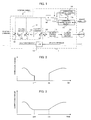
- FIG. 1 is a schematic block diagram showing a first embodiment of the present invention.
- a servomotor controller 1 has a position control section 10, a velocity control section 11 and a current control section 12, and as the elements relating to the present invention, also has a correction amount generating section 15, a correction amount holding section 16, selector switches 17a, 17b operating in an associated manner, and a coefficient section 18.
- a velocity command is obtained as follows: A position feedback is obtained by integrating means 13 performing integration of velocity feedbacks from a velocity detector such as a pulse encoder provided to a servomotor M; then, a position deviation is obtained by a subtractor 20 subtracting the position feedback from a position command outputted from a host controller such as a numerical controller; and then, by multiplying the position deviation by a position gain Kp as indicated by reference numeral 14, a velocity command is obtained.
- a velocity deviation is obtained by a subtractor 21 subtracting a velocity feedback from the velocity command obtained, and a current command (torque command) is obtained by performing a velocity control procedure based on the velocity deviation obtained.
- a servomotor M is driven by performing current feedback control based on the current command (torque command) obtained, in the same manner as in the prior art.
- the control on the servomotor M consisting of the above-mentioned position, velocity and current feedback controls, is the same as that in the prior servomotor controllers. Further, the control procedures are performed by a processor, in which respect, the present embodiment does not differ from the prior servomotor controllers.
- the present embodiment has a correction amount generating section 15 for generating a correction amount for correcting a position command, a position deviation or a velocity command, a correction amount holding section 16 for holding the correction amount generated, selector switches 17a, 17b operating in an associated manner for choosing between a correction amount sent from the correction amount generating section 15 and a correction amount sent from the correction amount holding section 16, and a coefficient section 18 for multiplying the correction amount chosen by the selector switch 17a by a coefficient k, thereby obtaining a correction amount adapted for an object for which correction is performed.
- the coefficient section multiplies the correction amount from the correction amount generating section 15 or the correction amount holding section 16, chosen by the selector switch 17a, by a different coefficient k, depending on whether correction is performed by the adder 19 adding a correction amount to a position command, or the adder 21 adding a correction amount to a position deviation, or the adder 22 adding a correction amount to a velocity command.
- adders 19, 21 and 22 are provided, it is possible to arrange such that only one of these adders is provided to correct a position command, a position deviation or a velocity command.
- the correction amount generating section 15 detects the value of a fluctuation factor for a to-be-controlled object such as a machine, and obtains a correction amount for correcting any of a position command, position deviation and velocity command, based on the value of the fluctuation factor detected. For example, in order to prevent an increase in position error of a movable part driven by the servomotor due to thermal expansion of a transmission mechanism such as a ball screw/nut mechanism, the correction amount generating section obtains a correction amount based on a signal from a sensor such as a temperature sensor for detecting the machine temperature.
- the correction amount holding section 16 updates the stored correction amount by storing a correction amount generated by the correction amount generating section 15 and sent via the selector switch 17b, successively.
- the selector switch 17a chooses the correction amount holding section 16
- the selector switch 17b is opened, so that the correction amount holding section 16 stops the updating of the correction amount and holds the correction amount at the time the connection of the selector switches 17a, 17b was changed.
- the item to which emphasis should be given varies depending on the operating state, such that an increase in the accuracy of positioning an object driven by a servomotor, such as a workpiece or a tool, should be intended, or an improvement in the quality of a machined surface should be intended.
- a servomotor such as a workpiece or a tool
- the highly accurate positioning taking account of thermal extension of the machine can be achieved by detecting the machine temperature, obtaining a correction amount for a position command or position deviation based on the temperature detected, and performing correction to the position command or position deviation.
- the correction amount varies with fluctuation of the detected temperature, so that the position command or position deviation corrected using the varying correction amount also varies, which causes lowering of the accuracy of a machined surface.
- the position command or position deviation does not suffer a variation due to correction, so that the quality of a machined surface can be maintained.
- the present embodiment is arranged to switch between performing correction using a varying correction amount obtained by the correction amount generating section 15 and performing correction using a fixed correction amount stored in the correction amount holding section 16, depending on the machine's operating state, based on an external signal 2. It can be arranged to simply switch between performing and non-performing of correction, depending on the machine's operating state, namely depending on whether emphasis should be given to positioning or the like or the quality of a machined surface.
- the present embodiment further intends to reduce a change in correction amount at the time of a switch, to prevent the machine from suffering a shock at the time of a switch between performing and non-performing of correction.
- the position command or position deviation can vary to a great degree when correction is started or stopped, which can cause a rapid movement of the servomotor M and give a shock to the machine.
- the connection of the selector switches 17a and 17b is changed to choose the output of the correction amount generating section 15 or the output of the correction amount holding section 16, as a correction amount.
- the correction amount holding section 16 in FIG. 1 does not need to be provided.
- FIGS. 2 and 3 each show an example of how the correction amount changes when a switch between correction modes is made based on the external signal 2.
- FIG. 2 shows an example in which a switch between performing correction using a correction amount generated by the correction amount generating section 15 and performing no correction is made.
- FIG. 3 shows an example in which a switch between a correction amount sent from the correction amount generating section 15 and a correction amount sent from the correction amount holding section 16 is made, as shown in FIG. 1.
- FIG. 2 shows, in the case where a switch between performing and non-performing of correction is made, if the correction amount is great immediately before a switch to non-performing of correction is made, the position command or the like changes to a great degree. Further, if, at the time a switch to performing of correction is made to resume correction using a correction amount generated by the correction amount generating section 15, the correction amount generated by the correction amount generating section 15 is great, the correction amount is changed from "0" to the great value, so that the position command or the like changes to a great degree, which can give a shock to the machine. Meanwhile, if the correction amount generated by the correction amount generating section 15 is small at the time a switch between performing and non-performing of correction is made, a shock given to the machine is small.
- control can be performed by making a switch between performing and non-performing of correction without providing a correction amount holding section 16.
- the correction amount does not change to a great degree at the time of a switch as shown in FIG. 3, so that the machine does not suffer a shock.
- the correction amount holding section 16 holds a correction amount immediately before the external signal 2 came into the OFF state.
- the correction amount does not change at the time of the switch, and correction is performed using the fixed correction amount held in the correction amount holding section 16.
- the correction amount does not change rapidly, since the correction amount generating section 15 generates a correction amount using a filter, as described below.
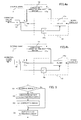
- FIGS. 4a and 4b show the details of the correction amount generating section 15 and of a switch between correction quantities based on the external signal 2.
- the correction amount generating section 15 comprises a digital filter 15a and a lag element 15b.
- FIG. 4a shows, when the external signal 2 is in the OFF state, the selector switch 17a chooses a correction amount stored in the correction amount holding section 16, and the selector switch 17b blocks the entry of a correction amount to the correction amount holding section 16.
- FIG. 4b shows, when the external signal 2 comes into the ON state, the connection of the selector switch 17a is changed to choose the output of the correction amount generating section 15, and the connection of the selector switch 17b is changed to allow a correction amount generated by the correction amount generating section 15 to enter the correction amount holding section 16.
- the correction amount generating section 15 when the external signal 2 comes into the ON state, a correction amount is obtained by the filter 15a processing a signal from the sensor, using a correction amount in the last cycle, which is stored in the lag element 15b, as an initial value. By this, a change in correction amount at the time of the switch is kept small. As shown in FIG. 4b, the output of the filter is sent via the selector switch 17a to the coefficient section, where it is multiplied by a coefficient k, which is set according to an object for which correction is performed, to generate and output a final correction amount. The output of the correction amount generating section 15 (output of the filter 15a) is also sent via the selector switch 17b to the correction amount holding section 16.
- the correction amount holding section 16 updates the stored correction amount by storing the new correction amount in place of the previous one.
- FIG. 4a shows, when the external signal 2 comes into the OFF state, the connection of the selector switches 17a, 17b, which are arranged to operate in an associated manner, is changed so that a correction amount stored in the correction amount holding section 16 is sent out.
- the external signal 2 can be a signal outputted from a host controller such as a numerical controller according to a machining program or the like, a signal manually entered, or a signal outputted from a sequencer or the like.
- a host controller such as a numerical controller according to a machining program or the like
- a signal manually entered or a signal outputted from a sequencer or the like.
- FIG. 5 shows a procedure for outputting a correction amount, which a processor of this servomotor controller 1 performs in parallel with a position and velocity feedback procedure.
- Step S1 whether the external signal is 1 (ON) or not is determined. If the external signal is not ON, a correction amount stored in a register A multiplied by a coefficient k is outputted as a correction amount adapted for an object for which correction is performed (Step S4), with which the correction-amount outputting procedure ends. Based on the correction amount thus outputted, a position command, a position deviation or a velocity command is corrected as described above, and the position and velocity output procedure is performed.
- a correction amount is calculated by performing a correction-amount calculation procedure based on a signal from the sensor, using a correction amount stored in the register A as an initial value (Step S2).
- the correction amount obtained is stored in the register A (Step S3), and then in Step 4, the correction amount stored in the register A multiplied by the coefficient k is sent out as a final correction amount, with which the current cycle of the correction-amount outputting procedure ends.
- the procedure of FIG.5 only needs to be modified in the following respects:
- the external signal is not "1”
- "0" is put into the register A, while the other things remain unchanged;
- the correction-amount outputting procedure ends without sending out a correction amount.
- Step S2 a correction amount is obtained in Step S2 by performing the correction-amount calculation processing based on a signal from the sensor, not using a correction amount stored in the register A as an initial value;
- the correction amount thus obtained is stored in the register A, and the value stored in the register A multiplied by the coefficient k is sent out as a final correction amount.
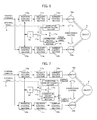
- FIG. 6 is a schematic block diagram showing a second embodiment of the present invention.
- the second embodiment is an embodiment of a controller designed to perform a tandem control in which one object 3 is driven by two servomotors Ma, Mb subjected to synchronous control.
- position control sections 10a, 10b, velocity control sections 11a, 11b and current control sections 12a, 12b are provided.
- the position control sections 10a, 10b each send out a velocity command through position feedback control as shown in FIG. 1, based on a motion command outputted from a host controller such as a numerical controller and a position feedback from a position detector provided to each of the servomotors Ma, Mb or a position detector provided for detecting the position of the object 3. It is to be noted that from the host controller, the same position command is outputted to the control sections 10a and 10b.
- the velocity control sections 11a, 11b each obtain a current command (torque command), through velocity feedback control, based on a velocity command for each and a velocity feedback from a velocity detector provided to each of the servomotors Ma, Mb.
- the current control sections 12a, 12b drive the servomotors Ma, Mb, respectively, to move the object 3, through current feedback control, based on a current command (torque command) for each and a current feedback from a current detector provided for detecting a drive current for each of the servomotors Ma, Mb.
- the present embodiment further has a correction amount generating section 15, a correction amount holding section 16, selector switches 17a, 17b, and a coefficient section 18.
- a torque monitoring means is provided to each of the servomotors Ma, Mb.
- a correction amount is obtained from a difference between output torques of the servomotors monitored by the torque monitoring means, and a position command, position deviation or velocity command for control sections for controlling the servomotors Ma, Mb is corrected, as in the first embodiment.
- the present embodiment is similar to the first embodiment.
- the correction amount generating section 15 obtains a correction amount based on a difference between output torques of the servomotors Ma, Mb monitored by the torque monitoring means.
- the coefficient section 18 multiplies this correction amount by a set coefficient k, and using the resulting value, a position command, position deviation or velocity command is corrected.
- the correction amount generated by the correction amount generating section 15 is stored in the correction amount holding section 16.
- the selector switch 17a When the external signal 2 is OFF ("0"), the selector switch 17a is connected to the correction amount holding section 16, so that the coefficient section 18 multiplies a correction amount stored in the correction amount holding section 16 by the coefficient k, and using the resulting value, a position command, position deviation or velocity command is corrected.
- the selector switch 17b is opened so that the correction amount stored in the correction amount holding section 16 is not updated.
- This correction control is the same as that in the first embodiment, and the correction-amount outputting procedure in the present embodiment is the same as the procedure in the first embodiment shown in FIG. 5.
- the control sections for controlling the servomotors Ma, Mb perform position feed back control and velocity feedback control based on the position command, position deviation or velocity command thus corrected.
- the output torques of the servmotors Ma, Mb monitored by the torque monitoring means can be detected by providing torque detection means to the individual servomotors Ma, Mb.
- the output torques may be obtained in the form of actual current values (actual drive currents detected by current detectors) used in current feedback control by the current control sections 12a, 12b, or in the form of current commands (torque commands) which are the outputs of the velocity control sections 11a, 11b.
- the correction amount generating section 15 Based on a difference between the detected torques (actually detected torques, drive currents, current commands), the correction amount generating section 15 generates a correction amount.
- FIG. 7 shows an example in which a correction amount is obtained based on a difference between current commands (torque commands) generated by the velocity control sections 11a and 11b.
- a switch is made between correction using a correction amount generated by the correction amount generating section 15, namely, correction using a varying correction amount, and correction using a fixed correction amount held in the correction amount holding section 16.
- the correction amount is held constant, and when the accuracy of the motion path for high machining quality or the like is not required in particular (for example, the object is moved for positioning), correction is performed using a varying correction amount generated by the correction amount generating section 15 to prevent an increase in force exerted on the servomotors Ma, Mb.
- the second embodiment can be modified such that no correction amount holding section 16 is provided, and that when the external signal is OFF, the correction amount is set to "0" not to perform correction.
Landscapes
- Engineering & Computer Science (AREA)
- Human Computer Interaction (AREA)
- Manufacturing & Machinery (AREA)
- Physics & Mathematics (AREA)
- General Physics & Mathematics (AREA)
- Automation & Control Theory (AREA)
- Numerical Control (AREA)
- Control Of Position Or Direction (AREA)
- Automatic Control Of Machine Tools (AREA)
- Control Of Electric Motors In General (AREA)
Applications Claiming Priority (1)
| Application Number | Priority Date | Filing Date | Title |
|---|---|---|---|
| JP2006039276A JP4235210B2 (ja) | 2006-02-16 | 2006-02-16 | サーボモータの制御装置 |
Publications (3)
| Publication Number | Publication Date |
|---|---|
| EP1821168A2 true EP1821168A2 (de) | 2007-08-22 |
| EP1821168A3 EP1821168A3 (de) | 2009-05-06 |
| EP1821168B1 EP1821168B1 (de) | 2017-03-22 |
Family
ID=38024180
Family Applications (1)
| Application Number | Title | Priority Date | Filing Date |
|---|---|---|---|
| EP07250376.6A Ceased EP1821168B1 (de) | 2006-02-16 | 2007-01-30 | Steuerung für einen Servomotor |
Country Status (4)
| Country | Link |
|---|---|
| US (1) | US7531981B2 (de) |
| EP (1) | EP1821168B1 (de) |
| JP (1) | JP4235210B2 (de) |
| CN (1) | CN100465824C (de) |
Families Citing this family (12)
| Publication number | Priority date | Publication date | Assignee | Title |
|---|---|---|---|---|
| JP5301180B2 (ja) * | 2008-03-13 | 2013-09-25 | 東芝機械株式会社 | 同期型acサーボモータおよびその制御システム |
| JP4620159B2 (ja) * | 2009-05-21 | 2011-01-26 | ファナック株式会社 | 周期的な往復動作を制御するサーボモータ制御装置 |
| JP5689704B2 (ja) * | 2010-08-08 | 2015-03-25 | 日本電産サンキョー株式会社 | モータ制御装置およびモータ制御方法 |
| TWI494725B (zh) * | 2012-12-18 | 2015-08-01 | Ind Tech Res Inst | 控制裝置、控制方法及位置命令補償方法 |
| JP5837148B1 (ja) * | 2014-06-18 | 2015-12-24 | ファナック株式会社 | 工作機械の熱変位補正装置 |
| JP5890488B1 (ja) * | 2014-08-05 | 2016-03-22 | ファナック株式会社 | ツールをワークに押付けて作業を行うロボットの制御装置 |
| TWI558089B (zh) | 2015-08-06 | 2016-11-11 | 財團法人工業技術研究院 | 多軸馬達同動控制系統及其方法 |
| US11003154B2 (en) * | 2016-05-10 | 2021-05-11 | Panasonic Intellectual Property Managenent Co., Ltd. | Motor control system |
| JP6568035B2 (ja) | 2016-10-04 | 2019-08-28 | ファナック株式会社 | サーボモータ制御装置、サーボモータ制御方法、及びサーボモータ制御用プログラム |
| CN112020824B (zh) * | 2018-04-27 | 2024-08-23 | 松下知识产权经营株式会社 | 螺纹紧固装置用的伺服放大器 |
| WO2021124603A1 (ja) * | 2019-12-16 | 2021-06-24 | 株式会社日立産機システム | モータ制御装置、モータ制御方法 |
| JPWO2024057386A1 (de) * | 2022-09-13 | 2024-03-21 |
Family Cites Families (21)
| Publication number | Priority date | Publication date | Assignee | Title |
|---|---|---|---|---|
| JPH0293706A (ja) | 1988-09-29 | 1990-04-04 | Toyoda Mach Works Ltd | 位置決め装置 |
| JPH03110607A (ja) * | 1989-09-26 | 1991-05-10 | Fanuc Ltd | サーボモータの制御方式 |
| JPH04261751A (ja) * | 1991-01-08 | 1992-09-17 | Yamazaki Mazak Corp | 工作機械における熱変位補正装置 |
| JP2954378B2 (ja) * | 1991-04-25 | 1999-09-27 | 三菱電機株式会社 | 電動機サーボ系の制御装置 |
| JP3269151B2 (ja) | 1992-12-26 | 2002-03-25 | トヨタ自動車株式会社 | フィードバック式加工条件補正装置 |
| KR0160997B1 (ko) * | 1992-09-18 | 1998-12-15 | 윤종용 | 로보트위치제어장치에서의 써보의 웜업드리프트 보상방법 |
| JP2871993B2 (ja) * | 1993-03-31 | 1999-03-17 | 日本電気株式会社 | サーボモータの位置制御装置 |
| JPH07110717A (ja) * | 1993-08-19 | 1995-04-25 | Fanuc Ltd | モータの制御方式 |
| JP3129622B2 (ja) * | 1994-12-26 | 2001-01-31 | ファナック株式会社 | フルクローズド・ループ方式における象限突起補正方法 |
| DE19509325A1 (de) * | 1995-03-15 | 1996-09-19 | Siemens Ag | Verfahren und Vorrichtung zur automatischen Drift-Kompensation von lagegeregelten Achsen und Spindeln |
| JP3292455B2 (ja) | 1997-10-08 | 2002-06-17 | ブラザー工業株式会社 | 工作機械の熱変位量算出装置及び記憶媒体 |
| WO2000019288A1 (en) | 1998-09-28 | 2000-04-06 | Kabushiki Kaisha Yaskawa Denki | Position controller |
| WO2000070739A1 (fr) * | 1999-05-14 | 2000-11-23 | Mitsubishi Denki Kabushiki Kaisha | Servocommande |
| US6744233B1 (en) * | 2000-11-01 | 2004-06-01 | Mitsubishi Denki Kabushiki Kaisha | Servo controller and method |
| JP3687958B2 (ja) | 2001-03-30 | 2005-08-24 | 東芝機械株式会社 | 位置制御装置および位置制御方法 |
| JP3756793B2 (ja) | 2001-07-27 | 2006-03-15 | オークマ株式会社 | 工作機械の熱変位補正装置 |
| JP3910482B2 (ja) * | 2002-04-26 | 2007-04-25 | Thk株式会社 | 数値制御工作機械における加工誤差補正方法及びこれを用いた研削盤 |
| JP3923047B2 (ja) * | 2003-03-04 | 2007-05-30 | ファナック株式会社 | 同期制御装置 |
| JP4242229B2 (ja) | 2003-07-28 | 2009-03-25 | 株式会社森精機製作所 | 工作機械の熱変位補正方法およびその装置 |
| CN100461612C (zh) * | 2004-06-11 | 2009-02-11 | 三菱电机株式会社 | 电动机的控制装置及其控制方法 |
| JP4335123B2 (ja) * | 2004-11-26 | 2009-09-30 | ファナック株式会社 | 制御装置 |
-
2006
- 2006-02-16 JP JP2006039276A patent/JP4235210B2/ja not_active Expired - Fee Related
-
2007
- 2007-01-30 EP EP07250376.6A patent/EP1821168B1/de not_active Ceased
- 2007-02-08 US US11/703,797 patent/US7531981B2/en active Active
- 2007-02-15 CN CNB2007100788024A patent/CN100465824C/zh not_active Expired - Fee Related
Also Published As
| Publication number | Publication date |
|---|---|
| EP1821168B1 (de) | 2017-03-22 |
| US20070188123A1 (en) | 2007-08-16 |
| JP4235210B2 (ja) | 2009-03-11 |
| EP1821168A3 (de) | 2009-05-06 |
| CN100465824C (zh) | 2009-03-04 |
| US7531981B2 (en) | 2009-05-12 |
| JP2007219812A (ja) | 2007-08-30 |
| CN101025615A (zh) | 2007-08-29 |
Similar Documents
| Publication | Publication Date | Title |
|---|---|---|
| US7531981B2 (en) | Controller for servomotor | |
| JP3923047B2 (ja) | 同期制御装置 | |
| EP1667001B1 (de) | Steuervorrichtung | |
| US9594357B2 (en) | Thermal displacement compensating device of machine tool | |
| WO2001029628A1 (en) | Nc machine tool, and method of controlling nc machine tool | |
| US8299743B2 (en) | Machine tool and controlling method thereof | |
| EP3795309B1 (de) | Verfahren zur erkennung von codiereranomalien, betriebssteuerungsvorrichtung, roboter und robotersystem | |
| JP5890473B2 (ja) | モータを制御するモータ制御装置 | |
| US20130320908A1 (en) | Servo controller having function for correcting amount of expansion/contraction of ball screw | |
| JP2008225533A (ja) | サーボ制御装置 | |
| JP2011134169A (ja) | 制御パラメータ調整方法及び調整装置 | |
| JPH11305839A (ja) | 複数のサーボモータの制御方法 | |
| JP2007226836A (ja) | 数値制御工作機械の制御方法及び数値制御工作機械 | |
| KR20010041353A (ko) | 동기제어장치 | |
| US20060255759A1 (en) | Numerical controller | |
| TWI486231B (zh) | 扭矩控制裝置 | |
| JP4636271B2 (ja) | サーボ制御装置とその調整方法 | |
| JPH08110808A (ja) | 数値制御工作機械の制御方法及び装置 | |
| JP3854602B2 (ja) | 多軸駆動装置 | |
| JP2006018431A (ja) | サーボ制御装置 | |
| JP3259736B2 (ja) | 数値制御ネジ切り装置 | |
| JPH07266190A (ja) | 数値制御装置 | |
| US20190193139A1 (en) | Servomotor control device in processing machine | |
| KR101435197B1 (ko) | 공작기계의 수직축 자중 보상 제어장치 및 방법 | |
| JPH068053A (ja) | 放電加工方法 |
Legal Events
| Date | Code | Title | Description |
|---|---|---|---|
| PUAI | Public reference made under article 153(3) epc to a published international application that has entered the european phase |
Free format text: ORIGINAL CODE: 0009012 |
|
| AK | Designated contracting states |
Kind code of ref document: A2 Designated state(s): AT BE BG CH CY CZ DE DK EE ES FI FR GB GR HU IE IS IT LI LT LU LV MC NL PL PT RO SE SI SK TR |
|
| AX | Request for extension of the european patent |
Extension state: AL BA HR MK YU |
|
| PUAL | Search report despatched |
Free format text: ORIGINAL CODE: 0009013 |
|
| AK | Designated contracting states |
Kind code of ref document: A3 Designated state(s): AT BE BG CH CY CZ DE DK EE ES FI FR GB GR HU IE IS IT LI LT LU LV MC NL PL PT RO SE SI SK TR |
|
| AX | Request for extension of the european patent |
Extension state: AL BA HR MK RS |
|
| 17P | Request for examination filed |
Effective date: 20091105 |
|
| AKX | Designation fees paid |
Designated state(s): DE |
|
| RAP1 | Party data changed (applicant data changed or rights of an application transferred) |
Owner name: FANUC CORPORATION |
|
| 17Q | First examination report despatched |
Effective date: 20110510 |
|
| GRAP | Despatch of communication of intention to grant a patent |
Free format text: ORIGINAL CODE: EPIDOSNIGR1 |
|
| INTG | Intention to grant announced |
Effective date: 20161017 |
|
| STAA | Information on the status of an ep patent application or granted ep patent |
Free format text: STATUS: GRANT OF PATENT IS INTENDED |
|
| GRAS | Grant fee paid |
Free format text: ORIGINAL CODE: EPIDOSNIGR3 |
|
| GRAA | (expected) grant |
Free format text: ORIGINAL CODE: 0009210 |
|
| STAA | Information on the status of an ep patent application or granted ep patent |
Free format text: STATUS: THE PATENT HAS BEEN GRANTED |
|
| AK | Designated contracting states |
Kind code of ref document: B1 Designated state(s): DE |
|
| REG | Reference to a national code |
Ref country code: DE Ref legal event code: R096 Ref document number: 602007050262 Country of ref document: DE |
|
| REG | Reference to a national code |
Ref country code: DE Ref legal event code: R097 Ref document number: 602007050262 Country of ref document: DE |
|
| PLBE | No opposition filed within time limit |
Free format text: ORIGINAL CODE: 0009261 |
|
| STAA | Information on the status of an ep patent application or granted ep patent |
Free format text: STATUS: NO OPPOSITION FILED WITHIN TIME LIMIT |
|
| 26N | No opposition filed |
Effective date: 20180102 |
|
| REG | Reference to a national code |
Ref country code: DE Ref legal event code: R082 Ref document number: 602007050262 Country of ref document: DE Representative=s name: HL KEMPNER PATENTANWALT, RECHTSANWALT, SOLICIT, DE |
|
| PGFP | Annual fee paid to national office [announced via postgrant information from national office to epo] |
Ref country code: DE Payment date: 20210119 Year of fee payment: 15 |
|
| REG | Reference to a national code |
Ref country code: DE Ref legal event code: R119 Ref document number: 602007050262 Country of ref document: DE |
|
| PG25 | Lapsed in a contracting state [announced via postgrant information from national office to epo] |
Ref country code: DE Free format text: LAPSE BECAUSE OF NON-PAYMENT OF DUE FEES Effective date: 20220802 |