EP1824704B1 - Vorrichtung zur befestigung an einem solch eine vorrichtung umfassenden fahrzeug - Google Patents
Vorrichtung zur befestigung an einem solch eine vorrichtung umfassenden fahrzeug Download PDFInfo
- Publication number
- EP1824704B1 EP1824704B1 EP04800407A EP04800407A EP1824704B1 EP 1824704 B1 EP1824704 B1 EP 1824704B1 EP 04800407 A EP04800407 A EP 04800407A EP 04800407 A EP04800407 A EP 04800407A EP 1824704 B1 EP1824704 B1 EP 1824704B1
- Authority
- EP
- European Patent Office
- Prior art keywords
- vehicle
- shiftable
- active position
- horizontally extending
- substantially horizontally
- Prior art date
- Legal status (The legal status is an assumption and is not a legal conclusion. Google has not performed a legal analysis and makes no representation as to the accuracy of the status listed.)
- Expired - Lifetime
Links
- 238000006073 displacement reaction Methods 0.000 claims description 26
- 230000005484 gravity Effects 0.000 description 7
- 239000000725 suspension Substances 0.000 description 7
- 239000000463 material Substances 0.000 description 4
- 229920003023 plastic Polymers 0.000 description 4
- 239000004033 plastic Substances 0.000 description 4
- 238000010276 construction Methods 0.000 description 3
- 230000007423 decrease Effects 0.000 description 3
- 230000000284 resting effect Effects 0.000 description 3
- 239000004411 aluminium Substances 0.000 description 2
- 229910052782 aluminium Inorganic materials 0.000 description 2
- XAGFODPZIPBFFR-UHFFFAOYSA-N aluminium Chemical compound [Al] XAGFODPZIPBFFR-UHFFFAOYSA-N 0.000 description 2
- 238000013016 damping Methods 0.000 description 2
- 229910052751 metal Inorganic materials 0.000 description 2
- 239000002184 metal Substances 0.000 description 2
- 239000007787 solid Substances 0.000 description 2
- 230000003313 weakening effect Effects 0.000 description 2
- 241000820985 Goneplax rhomboides Species 0.000 description 1
- 229910000831 Steel Inorganic materials 0.000 description 1
- 230000002745 absorbent Effects 0.000 description 1
- 239000002250 absorbent Substances 0.000 description 1
- 238000010521 absorption reaction Methods 0.000 description 1
- 230000003213 activating effect Effects 0.000 description 1
- 230000004913 activation Effects 0.000 description 1
- 230000033228 biological regulation Effects 0.000 description 1
- 230000003247 decreasing effect Effects 0.000 description 1
- 230000001419 dependent effect Effects 0.000 description 1
- 230000000694 effects Effects 0.000 description 1
- 230000007613 environmental effect Effects 0.000 description 1
- 229920002457 flexible plastic Polymers 0.000 description 1
- 238000009434 installation Methods 0.000 description 1
- 238000004519 manufacturing process Methods 0.000 description 1
- 230000006641 stabilisation Effects 0.000 description 1
- 238000011105 stabilization Methods 0.000 description 1
- 229910001220 stainless steel Inorganic materials 0.000 description 1
- 239000010935 stainless steel Substances 0.000 description 1
- 239000010959 steel Substances 0.000 description 1
- 239000013585 weight reducing agent Substances 0.000 description 1
Images

Classifications
-
- B—PERFORMING OPERATIONS; TRANSPORTING
- B60—VEHICLES IN GENERAL
- B60R—VEHICLES, VEHICLE FITTINGS, OR VEHICLE PARTS, NOT OTHERWISE PROVIDED FOR
- B60R19/00—Wheel guards; Radiator guards, e.g. grilles; Obstruction removers; Fittings damping bouncing force in collisions
- B60R19/02—Bumpers, i.e. impact receiving or absorbing members for protecting vehicles or fending off blows from other vehicles or objects
- B60R19/48—Bumpers, i.e. impact receiving or absorbing members for protecting vehicles or fending off blows from other vehicles or objects combined with, or convertible into, other devices or objects, e.g. bumpers combined with road brushes, bumpers convertible into beds
-
- B—PERFORMING OPERATIONS; TRANSPORTING
- B60—VEHICLES IN GENERAL
- B60R—VEHICLES, VEHICLE FITTINGS, OR VEHICLE PARTS, NOT OTHERWISE PROVIDED FOR
- B60R19/00—Wheel guards; Radiator guards, e.g. grilles; Obstruction removers; Fittings damping bouncing force in collisions
- B60R19/56—Fittings damping bouncing force in truck collisions, e.g. bumpers; Arrangements on high-riding vehicles, e.g. lorries, for preventing vehicles or objects from running thereunder
-
- B—PERFORMING OPERATIONS; TRANSPORTING
- B60—VEHICLES IN GENERAL
- B60R—VEHICLES, VEHICLE FITTINGS, OR VEHICLE PARTS, NOT OTHERWISE PROVIDED FOR
- B60R19/00—Wheel guards; Radiator guards, e.g. grilles; Obstruction removers; Fittings damping bouncing force in collisions
- B60R19/02—Bumpers, i.e. impact receiving or absorbing members for protecting vehicles or fending off blows from other vehicles or objects
- B60R19/24—Arrangements for mounting bumpers on vehicles
- B60R19/38—Arrangements for mounting bumpers on vehicles adjustably or movably mounted, e.g. horizontally displaceable for securing a space between parked vehicles
-
- B—PERFORMING OPERATIONS; TRANSPORTING
- B60—VEHICLES IN GENERAL
- B60R—VEHICLES, VEHICLE FITTINGS, OR VEHICLE PARTS, NOT OTHERWISE PROVIDED FOR
- B60R21/00—Arrangements or fittings on vehicles for protecting or preventing injuries to occupants or pedestrians in case of accidents or other traffic risks
- B60R2021/0002—Type of accident
- B60R2021/0011—Rear collision or recoiling bounce after frontal collision
Definitions
- the present invention relates to a device for mounting on a vehicle, and more specifically for mounting on a large vehicle, such as a truck, trailer or semi-trailer. Further, the present invention relates to a vehicle comprising such a device.
- the force provided by the centre of gravity upon the back end of the truck may induce heavy stress on the rear axle of the truck, and when the load is moved even further back, it induces heavy stress on the rear end of the truck, which may damage the truck or potentially tip the truck backwards or sideways risking causing damage to the people and material around the vehicle as well as the vehicle itself.
- underrun protection devices such as on the lower front or rear section of a large vehicle, reinforced fixed or stowable structures such as a rigid or force-absorbing beam element arranged horizontally at the front and/or the rear section, impact load sensitive devices for creating a reactive force, and the like.
- underrun protection devices such as on the lower front or rear section of a large vehicle, reinforced fixed or stowable structures such as a rigid or force-absorbing beam element arranged horizontally at the front and/or the rear section, impact load sensitive devices for creating a reactive force, and the like.
- Different statutory requirements are applied in different countries concerning use and dimensions of underrun protection devices, including device ground clearance. Weight and space restrictions on the trucks may result in a limited space available for the load handling devices and an underrun protection device.
- the invention relates to a device for mounting on a vehicle according to claim 1.
- the invention further relates to a vehicle comprising at least one of said devices according to claim 9.
- one single device which constitutes both an underrun protection and a vehicle support.
- a better use of the space available on a frame of a vehicle onto which the device is to be mounted is achieved, and thus more space for other devices is provided, especially at the rear end of a large vehicle.
- the device according to the invention improves transport efficiency by lowering the overall weight, and thus decreases environmental and economical costs.
- the risk of tilting the vehicle while loading/unloading is significantly reduced, while the load inside the vehicle during standstill e.g. during crane operations is shifting.
- the invention comprises at least one shiftable carrier arm, which is mountable to a frame of said vehicle and is provided with at least one substantially horizontally extending beam, which in said first active position constitutes an underrun protection beam, and in said second active position constitutes a support beam, and displacement means for shifting of said at least one shiftable carrier arm between said first and second active positions.
- said device when mounted on a vehicle in said first active position, said device constitutes an underrun protection, presenting an impact element, i.e. the substantially horizontally extending beam/s and/or carrier arm/s, in the event of a collision with a small vehicle.
- said device when mounted on a vehicle in said second active position, constitutes a vehicle support, which is able to support and thus stabilize the part of the vehicle onto which said device is attached and is especially suited for supporting a single axle within the bogie for weight optimisation purposes.
- a further advantage involves the device providing a load force or weight-distributing element in the form of the support beam(s), when the support beam is adjacent the ground onto which the device rests.
- the at least one shiftable carrier arm is shiftable in a substantially vertical direction, and preferably shiftable by pivoting said at least one carrier arm around an axis substantially parallel to said at least one substantially horizontally extending beam.
- the forces countered by the device in the first and second active position may be relatively high and of a predetermined value.
- a simple construction of the device is assured, reducing production and mounting costs.
- the device is shiftable in a substantially vertical direction, e.g. when said carrier arms are provided as tube sections being mutually telescopically shiftable, the forces to be countered by said device may be set relatively high.
- the carrier arms may be shifted by pivoting them to an angle relative to vertical in order for the impact beam/s to be arranged for an improved impact distributing effect, which angle is dependent upon the clearance of the large vehicle and the force to be encountered in such a collision in order to reduce damage to both the large vehicle and the vehicle colliding with it.
- said displacement means include a hydraulic or pneumatic cylinder for pivoting said at least one carrier arm.
- the displacement means may be provided away from the direction of a possible impact force, thus protecting the displacement means against damage from said impact.
- an increased force available for shifting said carrier arms between said first and second active position is provided as compared to e.g. manual displacement means being provided.
- At least two carrier arms are provided, one substantially on each side of the at least one substantially horizontally extending beam.
- the stability of the underrun protection provided by said device is improved during a possible impact.
- an improved stabilization of the substantially horizontally extending beam is provided in both active positions to hold said beam horizontal.
- said at least two carrier arms are individually adjustable in length.
- the at least two carrier arms are adjustable in height in order for said device to conform to any uneven ground under the vehicle, which provides better vehicle support during load handling.
- said at least one substantially horizontally extending beam comprises a substantially flat plate element and/or a substantially tubular beam element.
- a part of said at least one substantially horizontally extending beam is provided with a flexible abutting element.
- a further impact absorbent is provided, which decreases the damages to a colliding small vehicle.
- uneven ground is further compensated with by providing the abutment element to form a substantially uniform, horizontally extending, level layer, upon which the support beam/s may rest substantially horizontally during load handling, which further improves the support to the large vehicle.
- the first active position may be selected between at least two different height positions. This may be advantageous when driving in different countries, when there are different requirements for the position of the underrun protection beam.
- said device is further shiftable into a third position.
- the device according to the invention may advantageous be stowed into a third, preferably inactive position, e.g. substantially above the lower part of the front or back end of the vehicle, or alternatively under the frame of the vehicle, when neither constituting an underrun protection nor a vehicle support.
- a third position may also be an active position of said device, e.g. providing a step for the operator or other useful function.
- said at least one device is mounted on a rear and/or front end of the vehicle.
- the weight of the load may be shifted towards the rear of the vehicle, and the force induced from this is moved further back.
- a rear position of said device according to the invention is advantageous, providing a stable support for the vehicle.
- a device provided at the front end of a vehicle is advantageous, either alone or in combination with a rear end position of a device according to the invention, thus providing vehicle support at the front end of the vehicle.
- a device constituting an underrun protection may be needed only at the rear or/and at the front end depending upon make and ground clearance of the large vehicle and the prevailing statutory requirements.
- said at least one substantially horizontally extending beam is extending to a length, which substantially equals the total width of said vehicle.
- an underrun protection may be provided in the first active position, which provides protection under the main part of the front and/or back end of the vehicle.
- the displacement means include hydraulic or pneumatic cylinders connected to a hydraulic or pneumatic system, respectively, on the vehicle.
- a hydraulic or pneumatic system is often available on many large vehicles, which simplifies installation and reduces the costs of a vehicle comprising a device according to the invention.
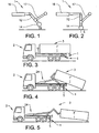
- a device 1 in a preferred embodiment of the present invention is shown in figure 1 in a very schematic side view in a first active position, in which it constitutes an underrun protection.
- the device 1 comprises a carrier arm 12 provided with an in a direction perpendicular to the plane of the paper on figure 1 substantially horizontally extending beam 14, which in said first position constitutes an underrun protection beam.
- displacement means 16 comprising a hydraulic or pneumatic cylinder, and a pivot arm 17, a first part upon said pivot arm 17 being pivotably attached to a first part on said carrier arm 12, and a second part of said pivot arm 17 being pivotably attachable to a frame of a vehicle (not shown), to which the device 1 is to be mounted.
- the underrun protection beam 14 is in a position having a predetermined ground clearance D between the lower part of said underrun protection beam 14 and the ground. This distance may be selected based on statutory requirements, often being less or equal to 550 mm.
- the device 1 of figure 1 is shown, also very schematically, in a side view in a second active position in which the device 1 constitutes a vehicle support.
- the displacement means 16 is connected to a carrier arm 12 and is attachable to said frame (not shown).
- the device 1 is shifted from the first active position in figure 1 to the second active position in figure 2 by pivoting the carrier arm 12 around an axis (not shown) extending parallel to said at least one substantially horizontally extending beam 14.
- the carrier arm 12 is placed in a substantially vertical position with one end of said carrier arm 12 adjacent to the ground, e.g.
- the device 1 comprises at least two carrier arms 12, which may preferably be of a longitudinally extending shape or any alternative form being suited for the device 1 constituting an underrun protection and a vehicle support, respectively, e.g. rhomboid, rectangular, square, semicircular, elliptical etc., and may in cross section be of any suitable dimension and shape, e.g. square, triangular, circular, semicircular or the like, and be solid or tubular. If the device 1 is provided with one carrier arm 12, this carrier arm 12 may advantageously be positioned substantially in the middle of the substantially horizontally extending beam 14 in order to provide stable vehicle support, when the device 1 is in the second active position.
- Each end of the substantially horizontally extending beam 14 is provided with one carrier arm 12 in order to remove the carrier arms 12 from the area of possible impact, when the device 1 constitutes an underrun protection, and in order to provide lateral stability during transport of said vehicle.
- Further carrier arms 12 may be provided on said device 1 in suitable positions on said of the substantially horizontally extending beam 14 in order to add further support to the vehicle during load handling, also to adapt to uneven ground, and further improve lateral stability to the device 1, when it constitutes an underrun protection.
- the device 1 comprises one or more substantially horizontally extending beams 14, e.g. two parallel extending beams of the same length, two or more beams in line, or the like.
- the substantially horizontally extending beam 14 may either be a substantially flat plate element (not shown) extending perpendicular to the plane of the paper, and/or be a solid or hollow substantially tubular beam element 14 of a generally round, semicircular, square, rectangular or other suitable cross section, and may be of any suitable shape, dimension, position on the carrier arm 12, and material for aiding the device in constituting an effective underrun protection and vehicle support.
- the device 1 comprising at least two carrier arms 12, at least one substantially horizontally extending beam 14, and the displacement means 16 further maybe comprising at least one pivot arm 17, may be made from any suitable material, e.g. stainless steel for the carrier arm/s 12 for increased strength when supporting the vehicle during handling of heavy loads, aluminium and/or plastic materials for the substantially horizontally extending beam 14 for increased impact force distribution or absorption, and steel, aluminium or plastic for said pivot arm 17.
- suitable material e.g. stainless steel for the carrier arm/s 12 for increased strength when supporting the vehicle during handling of heavy loads
- aluminium and/or plastic materials for the substantially horizontally extending beam 14 for increased impact force distribution or absorption
- steel, aluminium or plastic for said pivot arm 17.
- a vehicle according to the invention i.e. a conventional truck 2 comprising a device 1 according to the invention, in which the device 1 is in a first active position constituting an underrun protection.
- the device 1 is provided at the rear end of the truck 2 in order to counteract or absorb impact forces I from a possible collision with a small vehicle.
- a load 3 in the form of a container is provided on the truck 2 having a load, which imparts a gravitational force F in a vertical direction towards the ground.
- the displacement means 16 may incorporate a damping device that allows the underrun protection to absorb the impact force I in a more resilient manner.
- the damping device may constitute a valve that opens at a predefined load.
- a truck 2 as shown in figure 3 is shown during load handling, in which a device 1 according to the invention is in the second active position, thus providing a vehicle support for the truck 2.
- the load comprising a container 3 is shifted on the truck to the rear end by utilising a load handling device provided on the truck 2, e.g. a hook-lift 24.
- a load handling device provided on the truck 2, e.g. a hook-lift 24.
- the container load 3 has been shifted to a position beyond the rear end of the truck 2, such that the force F resulting from the weight of the container load is acting behind the rear end of the truck 2.
- the device 1 constitutes a vehicle support and the support force S has decreased as compared to the situation in figure 4 .
- the device 1 will also help to decrease the time to load and unload the vehicle.
- the air pressure in the air suspension for the vehicle described above must be as high as possible in order to support the load and prevent the rear of the vehicle to sink.
- the time to fill the air suspension is relatively long.
- the air suspension of an empty vehicle has an air pressure of 2 bars.
- To fill the suspension to 12 bars may take 20 seconds. Since the filling of the air suspension is automatic, the filling does not start until the load cycle has started. This means that a driver must start to load, and then wait for the suspension to fill before he can commence. With the device 1 in the second active position, the loading cycle can be performed without any waiting.
- a truck 2 with a load 3 in the form of a tipper body is shown during a tipping cycle, in which the device 1 according to the invention is in the second active position, thus providing a vehicle support for the truck 2.
- the goods to be tipped off is shifted to the rear end by utilising a load handling device provided on the truck 2, e.g. a dumping cylinder 22.
- a device 1 according to the invention may also be provided as a front end underrun protection and vehicle support.
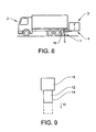
- FIG 7 is shown a schematic side view of a truck 2 comprising two such devices 1, 1' according to the invention, one 1' at the rear end and one 1 at the front end of the truck 2.
- a further vehicle support 1' is an advantage, especially for truck 2 provided with crane or hoist arrangements 23, where the centre of gravity shift may be taking place towards the front end of the truck 2 or even towards the lateral sides of the truck, because the resulting forces may then be counteracted upon by a further vehicle support 1'.
- the devices 1,1' may be shiftable to a position in the second active position in which both laterally acting forces and forces acting at the two ends of the truck 2 is counteracted upon by the devices 1, 1', where e.g. the carrier arm/s 14 are protruding laterally on the truck 2. Retracted in the first active positions, the devices 1,1' constitute a front underrun protection 1 and a rear underrun protection device 1'.
- FIG 8 is shown a truck 2, where the displacement means 16 are part of the hydraulic or pneumatic system already available on said truck 2, for a lift arrangement 4 holding a load 3.
- the displacement means 16 of said device 1 may also be provided as part of the general hydraulic or pneumatic system otherwise available on the truck. This may significantly reduce the implementing costs for said device 1.
- the displacement means 16 is provided with the device 1 having a separate hydraulic or pneumatic system, or may even be a manually operated mechanical device, e.g. operated by manually shifting the device 1 between said first and second active positions, and vice versa.
- the displacement means 16 may be provided on one or both sides of the device 1 on the extend of the substantially horizontally extending beam/s 14 for improved control of the position of the carrier arm/s 12 in the first and second active positions.
- the device 1 may also be adjustable in a cross-direction of the vehicle, that is the carrier arm on the right hand side and the carrier arm on the left hand side may be adjusted to different heights. This enables the device 1 to compensate for an uneven ground. It is also possible to incorporate adjustable supports at each end of the beam 14 in order to compensate for unevenness of the ground. The support may be manually or automatically adjustable. It is of course also possible to use removable supports to compensate for an uneven ground when necessary.
- FIG 9 is shown a side view of another embodiment of a device 1 according to the invention.
- the displacement means 16 are provided for attachment to a large vehicle (not shown), preferably to a frame of said vehicle.
- the displacement means 16 cooperates with a carrier arm 12, which by activation of said displacement means 16 is shiftable, as indicated with the arrow A1, between a first and second active position, as indicated with a full line and a broken line, respectively.
- the carrier arm 12 is provided with a beam 14, which in this embodiment is a flat plate element (not shown), extending substantially horizontally in a vertical plane perpendicular to the plane of the paper of figure 8 .
- the substantially horizontally extending beam/s 14 may be provided with an abutting element (not shown), e.g. a relatively thick and soft plastic layer or a soft flexible plastic or metal element, such as flexible metal wires, or durable plastic elements, or a combination hereof.
- Said abutting element is bendable or flexible in order to provide a soft impact distributing layer for said underrun protection beam, when said device 1 is in the first active position, and to provide a ground abutting layer for said support beam to rest upon in a substantially horizontal level, when said device 1 is in the second active position.
- Said abutting element provides a substantially horizontal, level and preferably non-flexible layer, when the device 1 is resting on the ground in the second active position, and a flexible layer, when the device 1 is suspended with a predetermined ground clearance in the first active position, reducing damage to smaller vehicles.
- Said device according to the invention may further be shiftable into a third active or inactive position (not shown), in which said device 1 constitutes neither an underrun protection nor a vehicle support.
- a third active position in which said device 1 constitutes neither an underrun protection nor a vehicle support.
- the device 1 may have other functions, e.g. a step aiding operators and drivers of the vehicle to enter and leave the loading area of the vehicle, or the like.
Landscapes
- Engineering & Computer Science (AREA)
- Mechanical Engineering (AREA)
- Vehicle Body Suspensions (AREA)
- Steering-Linkage Mechanisms And Four-Wheel Steering (AREA)
- Gripping Jigs, Holding Jigs, And Positioning Jigs (AREA)
- Devices For Checking Fares Or Tickets At Control Points (AREA)
- Body Structure For Vehicles (AREA)
- Automobile Manufacture Line, Endless Track Vehicle, Trailer (AREA)
Claims (14)
- Vorrichtung (1) zur Montage an einem Fahrzeug (2), wobei die Vorrichtung (1) zwischen einer ersten aktiven Position, in der sie einen Unterlaufschutz (I) bildet, und einer zweiten aktiven Position verstellbar ist, in der sie eine Fahrzeugstütze (S) bildet, wobei die Vorrichtung (1) wenigstens zwei verstellbare Tragarme (12, 17) umfasst, die an einem Rahmen des Fahrzeugs (2) anbringbar sind, wobei die Vorrichtung außerdem mit wenigstens einem sich im Wesentlichen horizontal erstreckenden Träger (14) versehen ist, der in der ersten aktiven Position einen Unterlaufschutzträger bildet und in der zweiten Position einen Stützträger bildet, und einer Verschiebeeinrichtung (16) für ein Verstellen des wenigstens einen verstellbaren Tragarms zwischen der ersten und zweiten aktiven Position versehen ist, wobei einer der wenigstens zwei Tragarmen (12, 17) im Wesentlichen auf jeder Seite des sich im Wesentlichen horizontal erstreckenden Trägers vorgesehen ist und die verstellbaren Tragarme (12, 17) in einer im wesentlichen vertikalen Richtung verstellbar sind, dadurch gekennzeichnet, dass die wenigstens zwei Tragarme (12, 17) in ihrer Länge einzeln einstellbar sind.
- Vorrichtung (1) nach Anspruch 1, bei der wenigstens einer der verstellbaren Tragarme (12) durch Verschwenkung des wenigstens einen Tragarms (12) um eine im Wesentlichen parallel zu dem wenigstens einen, sich im Wesentlichen horizontal erstreckenden Träger verlaufende Achse verstellbar ist.
- Vorrichtung (1) nach einem der vorhergehenden Ansprüche, bei der die Verschiebeeinrichtung (16) einen Hydraulikzylinder (16) für eine Verschwenkung des wenigstens einen Tragarms (12) umfasst.
- Vorrichtung (1) nach einem der vorhergehenden Ansprüche, bei der die Verschiebeeinrichtung (16) einen pneumatischen Zylinder für eine Verschwenkung des wenigstens einen Tragarms (12) umfasst.
- Vorrichtung (1) nach einem der vorhergehenden Ansprüche, bei der der wenigstens eine, sich im Wesentlichen horizontal erstreckende Träger ein im Wesentlichen flaches Plattenelement umfasst.
- Vorrichtung (1) nach einem der vorhergehenden Ansprüche, bei der der wenigstens eine, sich im Wesentlichen horizontal erstreckende Träger ein im Wesentlichen rohrförmiges Trägerelement umfasst.
- Vorrichtung (1) nach einem der vorhergehenden Ansprüche, bei der ein Teil des wenigstens einen, sich im Wesentlichen horizontal erstreckenden Trägers mit einem flexiblen Anschlagelement versehen ist.
- Vorrichtung (1) nach einem der vorhergehenden Ansprüche, bei der die Vorrichtung (1) außerdem in eine dritte Position verstellbar ist.
- Fahrzeug (2) mit wenigstens einer Vorrichtung nach einem der vorhergehenden Ansprüche, wobei die wenigstens eine Vorrichtung zwischen wenigstens einer ersten aktiven Position, in der sie einen Unterlaufschutz (I) bildet, und einer zweiten aktiven Position, in der sie eine Fahrzeugstütze während einer Lasthandhabung (S) bildet, verstellbar ist, wobei die wenigstens eine Vorrichtung (1) wenigstens einen verstellbaren Tragarm, der an einem Rahmen des Fahrzeugs (2) anbringbar ist und mit wenigstens einem sich im Wesentlichen horizontal erstreckenden Träger versehen ist, der in der ersten aktiven Position einen Unterlaufschutzträger und in der zweiten aktiven Position einen Stützträger bildet, und eine Verschiebeeinrichtung (16) für eine Verstellung des wenigstens einen verschiebbaren Tragarms zwischen der ersten und zweiten aktiven Stellung umfasst.
- Fahrzeug (2) nach Anspruch 9, bei dem wenigstens eine Vorrichtung an einem hinteren Ende des Fahrzeugs (2) angebracht ist.
- Fahrzeug (2) nach Anspruch 11 oder 12, bei dem wenigstens eine Vorrichtung (1) an einem vorderen Ende des Fahrzeugs (2) angebracht ist.
- Fahrzeug (2) nach einem der Ansprüche 9 bis 11, bei dem der wenigstens eine, sich im Wesentlichen horizontal erstreckende Träger sich in einer Länge erstreckt, die im Wesentlichen einer Gesamtbreite des Fahrzeugs (2) entspricht.
- Fahrzeug (2) nach einem der Ansprüche 9 bis 12, bei dem die Verschiebeeinrichtung (16) hydraulische Zylinder umfasst, die an ein Hydrauliksystem des Fahrzeugs (2) angeschlossen sind.
- Fahrzeug (2) nach einem der Ansprüche 9 bis 12, bei dem die Verschiebeeinrichtung (16) pneumatische Zylinder umfasst, die an ein pneumatisches System des Fahrzeugs (2) angeschlossen sind.
Applications Claiming Priority (1)
| Application Number | Priority Date | Filing Date | Title |
|---|---|---|---|
| PCT/SE2004/001750 WO2006057584A1 (en) | 2004-11-26 | 2004-11-26 | A device for mounting on a vehicle comprising such a device |
Publications (2)
| Publication Number | Publication Date |
|---|---|
| EP1824704A1 EP1824704A1 (de) | 2007-08-29 |
| EP1824704B1 true EP1824704B1 (de) | 2008-05-14 |
Family
ID=36498266
Family Applications (1)
| Application Number | Title | Priority Date | Filing Date |
|---|---|---|---|
| EP04800407A Expired - Lifetime EP1824704B1 (de) | 2004-11-26 | 2004-11-26 | Vorrichtung zur befestigung an einem solch eine vorrichtung umfassenden fahrzeug |
Country Status (6)
| Country | Link |
|---|---|
| US (1) | US20090074548A1 (de) |
| EP (1) | EP1824704B1 (de) |
| AT (1) | ATE395220T1 (de) |
| BR (1) | BRPI0419175A (de) |
| DE (1) | DE602004013849D1 (de) |
| WO (1) | WO2006057584A1 (de) |
Families Citing this family (3)
| Publication number | Priority date | Publication date | Assignee | Title |
|---|---|---|---|---|
| DE102009031708A1 (de) * | 2009-07-04 | 2011-01-05 | Krauss-Maffei Wegmann Gmbh & Co. Kg | Fahrzeug, insbesondere militärisches Fahrzeug |
| EP3498540B1 (de) * | 2017-12-13 | 2019-11-27 | Tirsan Treyler Sanayi Ve Ticaret Anonim Sirketi | Heckschutzausrüstung |
| DE102023109101A1 (de) * | 2023-04-11 | 2024-10-17 | Franz Xaver Meiller Fahrzeug- Und Maschinenfabrik - Gmbh & Co Kg | Unterfahrschutz-Baugruppe für ein Kipperfahrzeug |
Family Cites Families (6)
| Publication number | Priority date | Publication date | Assignee | Title |
|---|---|---|---|---|
| US1627317A (en) * | 1926-10-05 | 1927-05-03 | Burton K Cox | Combined bumper and jack |
| DE2309554A1 (de) * | 1973-02-26 | 1974-09-05 | Kockums Ind Ab | Anordnung an fahrzeugen |
| GB2090204A (en) * | 1980-12-15 | 1982-07-07 | Metalair Ltd | Rear bumper assembly for tipping-body vehicles |
| JPH05345545A (ja) * | 1992-06-16 | 1993-12-27 | Toshihiro Inoue | アウトリガーを装備する貨物自動車 |
| US5417540A (en) * | 1993-11-01 | 1995-05-23 | Cox; Henry | Cargo container handling and transport system |
| EP0827468A1 (de) * | 1995-04-28 | 1998-03-11 | Nai Neway, Inc. | Einrichtung zur einstellung der höhe eines fahrzeuguntergestells |
-
2004
- 2004-11-26 US US11/718,608 patent/US20090074548A1/en not_active Abandoned
- 2004-11-26 AT AT04800407T patent/ATE395220T1/de not_active IP Right Cessation
- 2004-11-26 WO PCT/SE2004/001750 patent/WO2006057584A1/en not_active Ceased
- 2004-11-26 DE DE602004013849T patent/DE602004013849D1/de not_active Expired - Lifetime
- 2004-11-26 EP EP04800407A patent/EP1824704B1/de not_active Expired - Lifetime
- 2004-11-29 BR BRPI0419175-7A patent/BRPI0419175A/pt not_active IP Right Cessation
Also Published As
| Publication number | Publication date |
|---|---|
| DE602004013849D1 (de) | 2008-06-26 |
| WO2006057584A1 (en) | 2006-06-01 |
| ATE395220T1 (de) | 2008-05-15 |
| EP1824704A1 (de) | 2007-08-29 |
| BRPI0419175A (pt) | 2007-12-18 |
| US20090074548A1 (en) | 2009-03-19 |
Similar Documents
| Publication | Publication Date | Title |
|---|---|---|
| FI89898C (fi) | Lyft- och transportanordning | |
| CN103832310B (zh) | 车轮支撑悬置组件 | |
| EP1753641B1 (de) | Anordnung für eine fahrzeugseitenverkleidung und fahrzeug mit einer solchen seitenverkleidung | |
| US4126357A (en) | Demountable tilting container assemblies for light vans and trucks | |
| EA000341B1 (ru) | Системы обработки контейнеров | |
| WO1996031430B1 (en) | A mechanism for loading and unloading containers onto vehicles | |
| US6032809A (en) | Apparatus for reducing the axle load of a multiaxle movable telescopic crane | |
| SK80796A3 (en) | Vehicle with superstructure | |
| US3610690A (en) | Support arrangement for truck body | |
| CN201040502Y (zh) | 多用型汽车运输拖车 | |
| US20090074548A1 (en) | device for mounting on a vehicle comprising such a device | |
| US5551831A (en) | Method and apparatus for elevating a cargo container chassis for storage | |
| CA1327829C (en) | Side tipper support system | |
| JP3177202B2 (ja) | 自走式コンテナーダンプ装置 | |
| RU2569152C2 (ru) | Способ и устройство на грузовых автомобилях для опрокидывания грузового бункера | |
| US2703656A (en) | Mechanism for unloading drums from vehicles | |
| CN105271063A (zh) | 一种驾驶室可向前翻转的叉车及降低叉车装箱高度的方法 | |
| JP3148740B2 (ja) | コンテナ専用車、コンテナおよびその積降ろし方法 | |
| US11850987B2 (en) | Chassis assembly for a delivery vehicle | |
| CN211995986U (zh) | 自卸车 | |
| JPH11335076A (ja) | 車両搭載用クレーンのベース | |
| GB2358173A (en) | Tractor activated tiltable load carrying trailer | |
| CA2052491A1 (en) | Load transferring device | |
| CN202345476U (zh) | 一种新型两轴自卸汽车的前置顶自卸装置 | |
| JPS6024648Y2 (ja) | サイドダンプ車の横転防止装置 |
Legal Events
| Date | Code | Title | Description |
|---|---|---|---|
| PUAI | Public reference made under article 153(3) epc to a published international application that has entered the european phase |
Free format text: ORIGINAL CODE: 0009012 |
|
| 17P | Request for examination filed |
Effective date: 20070626 |
|
| AK | Designated contracting states |
Kind code of ref document: A1 Designated state(s): AT BE BG CH CY CZ DE DK EE ES FI FR GB GR HU IE IS IT LI LU MC NL PL PT RO SE SI SK TR |
|
| RIN1 | Information on inventor provided before grant (corrected) |
Inventor name: GUSTAFSSON, JENS Inventor name: LILJEBLAD, BENNY Inventor name: REGNELL, HANS |
|
| 17Q | First examination report despatched |
Effective date: 20070926 |
|
| GRAP | Despatch of communication of intention to grant a patent |
Free format text: ORIGINAL CODE: EPIDOSNIGR1 |
|
| DAX | Request for extension of the european patent (deleted) | ||
| GRAS | Grant fee paid |
Free format text: ORIGINAL CODE: EPIDOSNIGR3 |
|
| GRAA | (expected) grant |
Free format text: ORIGINAL CODE: 0009210 |
|
| AK | Designated contracting states |
Kind code of ref document: B1 Designated state(s): AT BE BG CH CY CZ DE DK EE ES FI FR GB GR HU IE IS IT LI LU MC NL PL PT RO SE SI SK TR |
|
| REG | Reference to a national code |
Ref country code: GB Ref legal event code: FG4D |
|
| REG | Reference to a national code |
Ref country code: CH Ref legal event code: EP |
|
| REG | Reference to a national code |
Ref country code: IE Ref legal event code: FG4D Free format text: LANGUAGE OF EP DOCUMENT: FRENCH |
|
| REF | Corresponds to: |
Ref document number: 602004013849 Country of ref document: DE Date of ref document: 20080626 Kind code of ref document: P |
|
| REG | Reference to a national code |
Ref country code: SE Ref legal event code: TRGR |
|
| PG25 | Lapsed in a contracting state [announced via postgrant information from national office to epo] |
Ref country code: SI Free format text: LAPSE BECAUSE OF FAILURE TO SUBMIT A TRANSLATION OF THE DESCRIPTION OR TO PAY THE FEE WITHIN THE PRESCRIBED TIME-LIMIT Effective date: 20080514 |
|
| PG25 | Lapsed in a contracting state [announced via postgrant information from national office to epo] |
Ref country code: ES Free format text: LAPSE BECAUSE OF FAILURE TO SUBMIT A TRANSLATION OF THE DESCRIPTION OR TO PAY THE FEE WITHIN THE PRESCRIBED TIME-LIMIT Effective date: 20080825 Ref country code: FI Free format text: LAPSE BECAUSE OF FAILURE TO SUBMIT A TRANSLATION OF THE DESCRIPTION OR TO PAY THE FEE WITHIN THE PRESCRIBED TIME-LIMIT Effective date: 20080514 |
|
| PG25 | Lapsed in a contracting state [announced via postgrant information from national office to epo] |
Ref country code: AT Free format text: LAPSE BECAUSE OF FAILURE TO SUBMIT A TRANSLATION OF THE DESCRIPTION OR TO PAY THE FEE WITHIN THE PRESCRIBED TIME-LIMIT Effective date: 20080514 Ref country code: PL Free format text: LAPSE BECAUSE OF FAILURE TO SUBMIT A TRANSLATION OF THE DESCRIPTION OR TO PAY THE FEE WITHIN THE PRESCRIBED TIME-LIMIT Effective date: 20080514 |
|
| PG25 | Lapsed in a contracting state [announced via postgrant information from national office to epo] |
Ref country code: IS Free format text: LAPSE BECAUSE OF FAILURE TO SUBMIT A TRANSLATION OF THE DESCRIPTION OR TO PAY THE FEE WITHIN THE PRESCRIBED TIME-LIMIT Effective date: 20080914 |
|
| PG25 | Lapsed in a contracting state [announced via postgrant information from national office to epo] |
Ref country code: PT Free format text: LAPSE BECAUSE OF FAILURE TO SUBMIT A TRANSLATION OF THE DESCRIPTION OR TO PAY THE FEE WITHIN THE PRESCRIBED TIME-LIMIT Effective date: 20081014 Ref country code: CZ Free format text: LAPSE BECAUSE OF FAILURE TO SUBMIT A TRANSLATION OF THE DESCRIPTION OR TO PAY THE FEE WITHIN THE PRESCRIBED TIME-LIMIT Effective date: 20080514 Ref country code: DK Free format text: LAPSE BECAUSE OF FAILURE TO SUBMIT A TRANSLATION OF THE DESCRIPTION OR TO PAY THE FEE WITHIN THE PRESCRIBED TIME-LIMIT Effective date: 20080514 |
|
| PG25 | Lapsed in a contracting state [announced via postgrant information from national office to epo] |
Ref country code: RO Free format text: LAPSE BECAUSE OF FAILURE TO SUBMIT A TRANSLATION OF THE DESCRIPTION OR TO PAY THE FEE WITHIN THE PRESCRIBED TIME-LIMIT Effective date: 20080514 Ref country code: SK Free format text: LAPSE BECAUSE OF FAILURE TO SUBMIT A TRANSLATION OF THE DESCRIPTION OR TO PAY THE FEE WITHIN THE PRESCRIBED TIME-LIMIT Effective date: 20080514 Ref country code: BE Free format text: LAPSE BECAUSE OF FAILURE TO SUBMIT A TRANSLATION OF THE DESCRIPTION OR TO PAY THE FEE WITHIN THE PRESCRIBED TIME-LIMIT Effective date: 20080514 |
|
| PLBE | No opposition filed within time limit |
Free format text: ORIGINAL CODE: 0009261 |
|
| STAA | Information on the status of an ep patent application or granted ep patent |
Free format text: STATUS: NO OPPOSITION FILED WITHIN TIME LIMIT |
|
| 26N | No opposition filed |
Effective date: 20090217 |
|
| PG25 | Lapsed in a contracting state [announced via postgrant information from national office to epo] |
Ref country code: BG Free format text: LAPSE BECAUSE OF FAILURE TO SUBMIT A TRANSLATION OF THE DESCRIPTION OR TO PAY THE FEE WITHIN THE PRESCRIBED TIME-LIMIT Effective date: 20080814 Ref country code: EE Free format text: LAPSE BECAUSE OF FAILURE TO SUBMIT A TRANSLATION OF THE DESCRIPTION OR TO PAY THE FEE WITHIN THE PRESCRIBED TIME-LIMIT Effective date: 20080514 |
|
| PG25 | Lapsed in a contracting state [announced via postgrant information from national office to epo] |
Ref country code: MC Free format text: LAPSE BECAUSE OF NON-PAYMENT OF DUE FEES Effective date: 20081130 |
|
| REG | Reference to a national code |
Ref country code: CH Ref legal event code: PL |
|
| REG | Reference to a national code |
Ref country code: IE Ref legal event code: MM4A |
|
| PG25 | Lapsed in a contracting state [announced via postgrant information from national office to epo] |
Ref country code: IE Free format text: LAPSE BECAUSE OF NON-PAYMENT OF DUE FEES Effective date: 20081126 Ref country code: CH Free format text: LAPSE BECAUSE OF NON-PAYMENT OF DUE FEES Effective date: 20081130 Ref country code: LI Free format text: LAPSE BECAUSE OF NON-PAYMENT OF DUE FEES Effective date: 20081130 |
|
| PGFP | Annual fee paid to national office [announced via postgrant information from national office to epo] |
Ref country code: SE Payment date: 20091106 Year of fee payment: 6 |
|
| PGFP | Annual fee paid to national office [announced via postgrant information from national office to epo] |
Ref country code: NL Payment date: 20091104 Year of fee payment: 6 |
|
| PGFP | Annual fee paid to national office [announced via postgrant information from national office to epo] |
Ref country code: FR Payment date: 20091123 Year of fee payment: 6 Ref country code: GB Payment date: 20091125 Year of fee payment: 6 Ref country code: IT Payment date: 20091119 Year of fee payment: 6 |
|
| PG25 | Lapsed in a contracting state [announced via postgrant information from national office to epo] |
Ref country code: HU Free format text: LAPSE BECAUSE OF FAILURE TO SUBMIT A TRANSLATION OF THE DESCRIPTION OR TO PAY THE FEE WITHIN THE PRESCRIBED TIME-LIMIT Effective date: 20081115 Ref country code: CY Free format text: LAPSE BECAUSE OF FAILURE TO SUBMIT A TRANSLATION OF THE DESCRIPTION OR TO PAY THE FEE WITHIN THE PRESCRIBED TIME-LIMIT Effective date: 20080514 Ref country code: LU Free format text: LAPSE BECAUSE OF NON-PAYMENT OF DUE FEES Effective date: 20081126 |
|
| PG25 | Lapsed in a contracting state [announced via postgrant information from national office to epo] |
Ref country code: TR Free format text: LAPSE BECAUSE OF FAILURE TO SUBMIT A TRANSLATION OF THE DESCRIPTION OR TO PAY THE FEE WITHIN THE PRESCRIBED TIME-LIMIT Effective date: 20080514 |
|
| PG25 | Lapsed in a contracting state [announced via postgrant information from national office to epo] |
Ref country code: GR Free format text: LAPSE BECAUSE OF FAILURE TO SUBMIT A TRANSLATION OF THE DESCRIPTION OR TO PAY THE FEE WITHIN THE PRESCRIBED TIME-LIMIT Effective date: 20080815 |
|
| REG | Reference to a national code |
Ref country code: NL Ref legal event code: V1 Effective date: 20110601 |
|
| REG | Reference to a national code |
Ref country code: SE Ref legal event code: EUG |
|
| GBPC | Gb: european patent ceased through non-payment of renewal fee |
Effective date: 20101126 |
|
| REG | Reference to a national code |
Ref country code: FR Ref legal event code: ST Effective date: 20110801 |
|
| PG25 | Lapsed in a contracting state [announced via postgrant information from national office to epo] |
Ref country code: NL Free format text: LAPSE BECAUSE OF NON-PAYMENT OF DUE FEES Effective date: 20110601 |
|
| PG25 | Lapsed in a contracting state [announced via postgrant information from national office to epo] |
Ref country code: SE Free format text: LAPSE BECAUSE OF NON-PAYMENT OF DUE FEES Effective date: 20101127 |
|
| PG25 | Lapsed in a contracting state [announced via postgrant information from national office to epo] |
Ref country code: FR Free format text: LAPSE BECAUSE OF NON-PAYMENT OF DUE FEES Effective date: 20101130 |
|
| PG25 | Lapsed in a contracting state [announced via postgrant information from national office to epo] |
Ref country code: GB Free format text: LAPSE BECAUSE OF NON-PAYMENT OF DUE FEES Effective date: 20101126 |
|
| PG25 | Lapsed in a contracting state [announced via postgrant information from national office to epo] |
Ref country code: IT Free format text: LAPSE BECAUSE OF NON-PAYMENT OF DUE FEES Effective date: 20101126 |
|
| PGFP | Annual fee paid to national office [announced via postgrant information from national office to epo] |
Ref country code: DE Payment date: 20191129 Year of fee payment: 16 |
|
| REG | Reference to a national code |
Ref country code: DE Ref legal event code: R119 Ref document number: 602004013849 Country of ref document: DE |
|
| PG25 | Lapsed in a contracting state [announced via postgrant information from national office to epo] |
Ref country code: DE Free format text: LAPSE BECAUSE OF NON-PAYMENT OF DUE FEES Effective date: 20210601 |