EP1826122B1 - Plaque pour la distribution de corps sphériques - Google Patents
Plaque pour la distribution de corps sphériques Download PDFInfo
- Publication number
- EP1826122B1 EP1826122B1 EP07003524A EP07003524A EP1826122B1 EP 1826122 B1 EP1826122 B1 EP 1826122B1 EP 07003524 A EP07003524 A EP 07003524A EP 07003524 A EP07003524 A EP 07003524A EP 1826122 B1 EP1826122 B1 EP 1826122B1
- Authority
- EP
- European Patent Office
- Prior art keywords
- block
- openings
- base plate
- plate
- type
- Prior art date
- Legal status (The legal status is an assumption and is not a legal conclusion. Google has not performed a legal analysis and makes no representation as to the accuracy of the status listed.)
- Not-in-force
Links
Images


Classifications
-
- G—PHYSICS
- G01—MEASURING; TESTING
- G01F—MEASURING VOLUME, VOLUME FLOW, MASS FLOW OR LIQUID LEVEL; METERING BY VOLUME
- G01F11/00—Apparatus requiring external operation adapted at each repeated and identical operation to measure and separate a predetermined volume of fluid or fluent solid material from a supply or container, without regard to weight, and to deliver it
- G01F11/10—Apparatus requiring external operation adapted at each repeated and identical operation to measure and separate a predetermined volume of fluid or fluent solid material from a supply or container, without regard to weight, and to deliver it with measuring chambers moved during operation
- G01F11/12—Apparatus requiring external operation adapted at each repeated and identical operation to measure and separate a predetermined volume of fluid or fluent solid material from a supply or container, without regard to weight, and to deliver it with measuring chambers moved during operation of the valve type, i.e. the separating being effected by fluid-tight or powder-tight movements
- G01F11/14—Apparatus requiring external operation adapted at each repeated and identical operation to measure and separate a predetermined volume of fluid or fluent solid material from a supply or container, without regard to weight, and to deliver it with measuring chambers moved during operation of the valve type, i.e. the separating being effected by fluid-tight or powder-tight movements wherein the measuring chamber reciprocates
- G01F11/18—Apparatus requiring external operation adapted at each repeated and identical operation to measure and separate a predetermined volume of fluid or fluent solid material from a supply or container, without regard to weight, and to deliver it with measuring chambers moved during operation of the valve type, i.e. the separating being effected by fluid-tight or powder-tight movements wherein the measuring chamber reciprocates for fluent solid material
-
- B—PERFORMING OPERATIONS; TRANSPORTING
- B65—CONVEYING; PACKING; STORING; HANDLING THIN OR FILAMENTARY MATERIAL
- B65D—CONTAINERS FOR STORAGE OR TRANSPORT OF ARTICLES OR MATERIALS, e.g. BAGS, BARRELS, BOTTLES, BOXES, CANS, CARTONS, CRATES, DRUMS, JARS, TANKS, HOPPERS, FORWARDING CONTAINERS; ACCESSORIES, CLOSURES, OR FITTINGS THEREFOR; PACKAGING ELEMENTS; PACKAGES
- B65D90/00—Component parts, details or accessories for large containers
- B65D90/54—Gates or closures
- B65D90/58—Gates or closures having closure members sliding in the plane of the opening
- B65D90/60—Gates or closures having closure members sliding in the plane of the opening and having one or more openings
Definitions
- US 4,960,195 are devices by means of which cuboidal objects such as microchips are fed from a supply into a shaft, wherein the shaft has a rectangular or oval cross-section.
- US 4,960,195 discloses a horizontal plate having equal size openings of rectangular or oval cross-section, the plate having a recess on the upper side around each opening. At the plane of the plate surface, the circumference of the depression has an oval or rectangular shape. The wall and bottom of an oval depression are domed and the bottom of the oval depression tapers towards the center of the opening.
- Similar devices are out JP 36630/1987 known (cited after US 4,960,195 ).
- the plate contains a shaft with a rectangular cross-section. On one side, the plate has a recess of circular cross section which tapers conically to the center of the rectangular cross section.
- US 3,552,600 describes a ball dispenser, a device for the controlled removal of balls of the same size from a supply.
- the device disclosed therein comprises a reservoir, a hopper with a funnel-shaped feed and a feed screw.
- the latter contains a groove, by means of which a ball is removed from the shaft and ejected by turning the spindle.
- US 4,648,529 describes an arrangement with a ball reservoir connected to a circular funnel.
- the tapered end of the funnel points downwards and opens into a channel whose diameter corresponds to the diameter of the balls in the reservoir.
- the bullets that arrive are of the same size, in the channel in which they are arranged one behind the other.
- the channel is interrupted by a lock chamber, each of which can hold only a single ball.
- the lock chamber is arranged movably.
- the openings of the lock chamber are slightly offset, so that either a ball can leave the channel but not the lock chamber or that a ball can leave the lock chamber but not the channel.
- DE 198 18 417 C2 discloses a well for containing microbodies, such as spheres, wherein the height of the well dictates the number of microbodies that can be taken up.
- the upper end of the shaft is widened funnel-shaped.
- the microbodies are removed individually from the well by means of a suction mechanism.
- US 2002/0040521 A1 describes a template frame for positioning solder balls.
- the template frame consists of a plate with chambers in the form of holes, in each of which a single solder ball fits.
- the template frame is placed on a base so that the openings of the holes on the one hand facing the pad and on the other hand are open towards the top.
- Each hole is filled with a ball, so that the solder can then be fixed by heating with a laser at the respective position on the base.
- US 2002/0179696 A1 describes an arrangement for positioning of solder balls, in which a chamber of a template is filled from an overlying ball supply, wherein above the chamber a funnel-shaped recess is arranged, in which the balls collect from the supply and, for the purpose of filling, to the Chamber be led.
- EP 1 033 566 B1 discloses an apparatus for filling a plurality of individual grinding spaces with balls used as grinding media.
- the apparatus comprises a plate having 96 continuous circular openings arranged in regular form as 8x12 grids. The diameter of the openings is larger than the diameter of the balls.
- a slider is movably arranged, which represents the bottom of the openings in the inserted state, so that in this state balls are inserted into the openings can.
- the plate is placed over a block of grinding compartments arranged in the same 8x12 grid, so that the openings of the plate are aligned over the openings of the grinding compartments.
- the slide is pulled out of the plate and the grinding media fall into the grinding chambers.
- Spheres for example for use as grinding media, in many cases consist of materials which can not have smooth but rough surfaces. Examples include spheres made of glass or ceramic materials (eg sintered ceramics, resin porcelain), mineral rocks (eg marble, agate), metals (eg iron, tungsten carbide) or plastics (eg polyamide , Teflon) as well as biphasic bodies (eg with Teflon-coated steel balls).
- glass or ceramic materials eg sintered ceramics, resin porcelain
- mineral rocks eg marble, agate
- metals eg iron, tungsten carbide
- plastics eg polyamide , Teflon
- biphasic bodies eg with Teflon-coated steel balls.
- the starting point of the invention is a container filled with balls, which has in its bottom over one or more ⁇ ffnugen, wherein the diameter of each opening is large enough for the passage of a ball.
- the balls hinder each other when leaving through the opening (s), so that only a few or no balls of gravity can leave the supply. Even by shaking the reservoir, no uniform and predictable (amount per unit time) exit of balls through the openings is achieved.
- the object of the present invention is therefore to modify a base plate having one or more openings in such a way that the obstruction of the balls, leaving the storage container through the openings, is reduced.
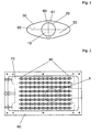
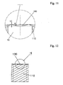
- the inventors have surprisingly found that a recess for feeding balls as in FIG. 1 shown leads to an improved exit of the balls from the supply in the opening. It was equally surprising that the feeding of balls succeeds particularly well when such depressions overlap with one another in the case of a plurality of juxtaposed openings.
- the object has been achieved by providing a device comprising a horizontal plate with two or more equal and perpendicular from the top to the bottom passing through openings, the plate on the upper side around each opening around a recess of the first kind (recess for feeding Spheres, hereinafter abbreviated V1 characterized in that the openings are circular, for example in the form of holes, the circumference of each V1 on the plane of the plate surface has an elliptical, oval or spindle-shaped form, the bottom of the V1 is inclined along the longitudinal axis toward the center of the opening, the center of each opening lies on the center of the longitudinal axis and the transverse axis of the circumference of the V1 arranged above it, two or more V1 are arranged on a common longitudinal axis, and the perimeters of two or more V1 overlap with each other.
- V1 characterized in that the openings are circular, for example in the form of holes, the circumference of each V1 on the plane of the plate surface has an ellipt
- a further embodiment of the invention is the use of a device according to the invention for distributing balls.
- a further embodiment of the invention is a method for removing a predetermined number of balls from a supply of substantially equal sized balls, comprising the steps of (a) providing a ball stock in a storage container having a device according to the invention as a bottom plate, wherein the radius of each opening is the average radius of the balls multiplied by a factor between 1.05 and 1.95; (B) providing a cuboid block having one or more vertically passing from the top to the bottom side through holes with circular cross section, wherein number, diameter and position of the holes which correspond to the openings of the bottom plate in step (a), the bottom plate rests on the block and the block is displaceable relative to the bottom plate, so that in a first position, the openings of the bottom plate are aligned with the holes of the block (position 1) and in a second position base plate and block are shifted from each other so that no balls through the openings of the bottom plate in the holes of
- balls of substantially the same size equivalent to “balls of about the same size”.
- the diameter of such balls varies on average by up to 10% or less.
- the diameter of such spheres preferably varies by up to 2 r K / 10 or less.
- the term "ball” also includes substantially spherical bodies. By this it is meant that the distance between the center and any point of the surface corresponding to the radius of an ideal sphere varies on average by up to 10% or less. Based on the average radius this corresponds to 2 r K / 10 or less.
- a “bore” is understood to mean a cylindrical hole made in a solid material.
- ball refers on the one hand a spherical body but in the context of the invention also an approximately spherical body, both each consisting of a solid material.
- the surface of a sphere can be smooth or rough.
- Spheres in the sense of definition are known, for example, as balls for ball bearings, beads made of glass or another material including natural materials (eg mother of pearl, amber, wood), or as "grinding balls” for ball mills.
- the latter are particularly preferred and are preferably made of steel or another metal, agate, tungsten carbide, sintered corundum or zirconium oxide.
- a container filled with balls This is provided with a level and horizontal bottom plate, in which plate for the purpose of discharging balls, one or more circular openings are introduced, in the form of perpendicular from the top to the bottom Side passing holes.
- the plate Around each opening, the plate has a recess of the first type on the upper side facing the balls (V1).
- the wall and the bottom of V1 are curved and the circumference of V1 has an elliptical, oval or spindle-shaped form on the plane of the plate surface.
- such a plate consists of a solid material, with polymer plastic, wood and metal being preferred. Metal is particularly preferred.
- One way to make such a depression in the plate is to use a mill with a spherical milling head.
- the term "circumference” refers to the contour left by milling or otherwise machining in the surface of the plate.
- the perimeter forms the boundary line separating the plane surface of the plate from the lumen of the depression.
- Wells according to the invention having an elliptical, oval or spindle-shaped circumference can be described by their extension along a longitudinal axis and a transverse axis.
- the invention relates to axisymmetric shapes having a circumference whose extent along the longitudinal axis is greater than the extent along the transverse axis. These axes also help to define the position of the bore opening in such a depression.
- the center of the opening (bore) lies in each case on the center of the longitudinal axis and the transverse axis of the circumference of the V1.
- the center of the opening and the intersection of the longitudinal and transverse axes of the circumference of the depression preferably coincide.
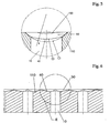
- the bottom of the V1 is inclined along the longitudinal axis to the center of the opening. That is, from the most distant edges of a depression along the longitudinal axis preferably leads an inclined plane to the bore opening.
- the inclination of the ground on each of the two halves of the longitudinal axis of the V1 has an inclination angle between 5 ° and 15 °. Very preferably, an angle of inclination between 11 ° and 12 °, and most preferably an inclination angle of 11.31 ° (1 ° corresponding to 1/360 of a full circle).
- the longitudinal extension of a single, not overlapping or connected with another V1 is measured from the distance of the intersections of the circumference and longitudinal axis (see FIG. 1 ).
- the distance of the points lying on the longitudinal axis with the greatest distance given as a multiple of the radius (r B ) of the bore, between 3 r B and 8 r B.
- the distance is between 5 r B and 7 r B , more preferably between 6 r B and 6.5 r B , and most preferably about 6.4 r B.
- the transverse extension of a single, not overlapping or connected with another V1 is measured from the distance of the intersections of the circumference and transverse axis (see FIG. 1 ).
- the distance of the points lying on the transverse axis with the greatest distance given as a multiple of the radius (r) of the bore, between 2.5 r B and 5 r B.
- the distance is between 2.2 r B and 3.5 r B , more preferably between 2.5 r B and 3 r B , and most preferably about 2.8 r B.
- the plate has two or more openings and two or more V1 are arranged on a common longitudinal axis, wherein two or more perimeters of a plurality of V1 overlap each other.
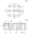
- a corresponding arrangement is for example in the Figures 2 and 3 shown.
- V1 Due to the overlapping of the two or more V1 at the longitudinal ends, straight lines are created in the contour. This may be due to the leadership of the milling head in the production of the wells in this type of arrangement.
- Very preferred is an arrangement of a plurality of apertures having a plurality of V1, wherein the plate comprises four or more apertures and the V1 are arranged so that two or more longitudinal axes and two or more transverse axes of these V1 cross each other at right angles.
- a recess of the second kind in the form of a groove connecting depressions of the first kind, hereinafter referred to as V2
- V2 a recess of the second kind
- Feeding the balls into the openings favorably influenced.
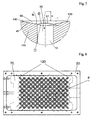
- a first opening with either one or more further openings is connected by one or more straight, horizontally extending curved V2, wherein the width of a V2, given as a multiple of the radius (r B ) of the bore, between 1 r B and 2 r B and the depth of a V2 is between 0.01 r B and 0.1 r B.
- vessels in the "multiwell” format are very particularly preferred.
- the company Integra Biosciences under the trade name Traxis ® container holders and small vessels in 8x12 format with 96 regularly arranged vessels are available.
- Such vessels are manufactured by Micronic BV (Lelystad, NL) and are widely used in biology, biochemistry or diagnostics.
- Micronic BV Lelystad, NL
- 96 openings are arranged as 8x12 grid in the plate.
- Another "multiwell" format includes 384 regularly arranged vessels.
- apertures are arranged in the plate 384 as 16x24 grid.
- Another particularly preferred embodiment of the invention is a device for filling vessels with substantially equal sized balls (ball dispenser) comprising (a) a reservoir of substantially equal size balls, the bottom plate of which is a device according to the invention; (B) a cuboid block having one or more vertically passing from the upper to the lower side bores, wherein the number, diameter and position of the bores which correspond to the openings of the bottom plate in step (a), the bottom plate rests against the block and the block against the Base plate is displaceable, so that in a first position, the openings of the bottom plate are aligned with the holes of the block and in a second position bottom plate and block are shifted from each other so that no balls can pass through the openings of the bottom plate in the holes of the block, and the thickness of the block is chosen so that in each hole a predetermined Number of balls can be stacked and that the uppermost ball at the height of the upper edge of the respective opening is substantially flush, without protruding beyond the edge; (c) an end plate slidable
- the plate according to the invention comprising one or more openings with V1 and possibly several V2 can be used as a device for distributing balls.
- the use for distributing balls that are substantially equal in size.
- the radius of each aperture in the plate and ball radius are preferably related.
- the diameter of each opening is slightly larger than the average ball diameter, so that balls can leave the supply through the opening (s).
- the radius of each opening expressed as a multiple of the average radius (r K ) of a sphere, is between 1.05 r K and 1.3 r K.
- each V1 is the distance of the points lying on the transverse axis with the greatest distance, given as a multiple of the average radius (r K ) of a sphere, between 3.5 r K and 4 r K.
- the inclination of the ground on each of the two halves of the longitudinal axis of the V1 has an inclination angle between 11 ° and 12 °.
- a device according to the invention for the distribution of spheres of a material having a density between 5 g / cm 3 and 8 g / cm 3 .
- a further aspect of the invention is a method for extracting a predetermined number of balls from a supply of substantially equal sized balls, comprising the steps of (a) providing a ball stock in a storage container having a device according to the invention as a bottom plate, the radius of each opening being the same average radius of the balls multiplied by a factor between 1.05 and 1.95; (B) providing a cuboid block having one or more vertically passing from the top to the bottom side through holes with circular cross section, wherein number, diameter and position of the holes which correspond to the openings of the bottom plate in step (a), the bottom plate rests on the block and the block is displaceable relative to the bottom plate, so that in a first position, the openings of the bottom plate are aligned with the holes of the block (position 1) and in a second position base plate and block are shifted from each other so that no balls through the openings of the bottom plate in the holes of the block can reach (position 2), and the length of the holes in the block is selected so that in each hole
- the ball supply is shaken in step (d).
- a very particularly preferred embodiment of the invention is characterized in that the state change from position 1 and position 3 to position 2 and position 4 takes place simultaneously. This ensures a particularly efficient handling of the method according to the invention.
Landscapes
- Engineering & Computer Science (AREA)
- Mechanical Engineering (AREA)
- Physics & Mathematics (AREA)
- Fluid Mechanics (AREA)
- General Physics & Mathematics (AREA)
- Laminated Bodies (AREA)
- Coating Apparatus (AREA)
- Automatic Analysis And Handling Materials Therefor (AREA)
- Feeding, Discharge, Calcimining, Fusing, And Gas-Generation Devices (AREA)
- Electric Connection Of Electric Components To Printed Circuits (AREA)
- Finish Polishing, Edge Sharpening, And Grinding By Specific Grinding Devices (AREA)
Claims (19)
- Dispositif comprenant une plaque horizontale (110) utilisable comme plaque de fond d'un réservoir et pourvue de deux ouvertures (10) ou plus de même taille la traversant verticalement du côté supérieur au côté inférieur, ladite plaque présentant sur le côté supérieur (70), autour de chaque ouverture (10), un creux (50) du premier type, la paroi et le fond dudit creux du premier type étant bombés,
caractérisé en ce que- les ouvertures (10) sont circulaires (20), par exemple sous forme de perçages,- la périphérie de chaque creux du premier type (30) présente au niveau de la surface (70) de la plaque une forme elliptique, ovale ou en forme de fuseau,- le fond du creux du premier type est incliné le long de l'axe longitudinal vers le milieu de l'ouverture,- le centre de chaque ouverture est situé à chaque fois sur le centre des axes longitudinal et transversal de la périphérie du creux du premier type disposé au-dessus d'elle,- deux creux ou plus du premier type sont disposés sur un axe longitudinal commun, et- les périphéries de deux creux ou plus du premier type chevauchent l'une sur l'autre. - Dispositif selon la revendication 1, caractérisé en ce que sur la périphérie du creux du premier type (30), la distance des points situés sur l'axe longitudinal et présentant le plus grand écart est comprise entre 3 et 8 fois le rayon du perçage.
- Dispositif selon une des revendications 1 ou 2, caractérisé en ce que sur la périphérie du creux du premier type (30), la distance des points situés sur l'axe transversal et présentant le plus grand écart est comprise entre 2,5 et 5 fois le rayon du perçage.
- Dispositif selon une des revendications 1 à 3, caractérisé en ce que l'inclinaison du fond (40) sur chacune des deux moitiés de l'axe longitudinal du creux du premier type présente un angle d'inclinaison compris entre 5° et 15°.
- Dispositif selon la revendication 4, caractérisé en ce que l'inclinaison du fond (40) sur chacune des deux moitiés de l'axe longitudinal du creux du premier type présente un angle d'inclinaison compris entre 11 ° et 12°.
- Dispositif selon la revendication 5, caractérisé en ce que l'angle d'inclinaison est 11,31 °.
- Dispositif selon une des revendications 1 à 6, caractérisé en ce que la plaque (110) comprend quatre ouvertures (10) ou plus, une pluralité de creux du premier type (50) étant disposés de telle manière que deux axes longitudinaux ou plus et deux axes transversaux ou plus desdits creux du premier type se croisent à angle droit.
- Dispositif selon la revendication 7, caractérisé en ce qu'une première ouverture (10) est reliée avec une ou plusieurs autres ouvertures (10) par un ou plusieurs creux du second type (130) bombés, droits et s'étendant horizontalement, la largeur d'un creux du second type étant comprise entre 1 et 2 fois le rayon du perçage et la profondeur d'un creux du second type étant comprise entre 0,01 et 0,1 fois le rayon du perçage.
- Dispositif selon une des revendications 7 ou 8, caractérisé en ce que 96 ouvertures sont ménagées dans la plaque, sous forme de grille 8x12.
- Dispositif selon une des revendications 7 ou 8, caractérisé en ce que 384 ouvertures sont ménagées dans la plaque, sous forme de grille 16x24.
- Dispositif selon une des revendications 1 à 10, comprenant en outre :(a) un réservoir contenant des corps sphériques sensiblement de même taille et dont la plaque de fond est le dispositif selon une des revendications 1 à 10 ;(b) un bloc en forme de parallélépipède, pourvu d'un ou plusieurs perçages traversant le bloc verticalement du côté supérieur au côté inférieur,- le nombre, le diamètre et la position des perçages correspondant à ceux des ouvertures de la plaque de fond à l'étape (a),- la plaque de fond (110) s'appuyant sur le bloc et le bloc pouvant être décalé par rapport à la plaque de fond, de sorte que dans une première position les ouvertures de la plaque de fond sont alignées avec les perçages du bloc et dans une seconde position la plaque de fond et le bloc sont décalés l'un par rapport à l'autre, empêchant ainsi les corps sphériques de parvenir à travers les ouvertures de la plaque de fond dans les perçages du bloc, et- l'épaisseur du bloc étant telle qu'un nombre prédéterminé de corps sphériques peuvent être empilés dans chaque perçage et que le corps sphérique le plus haut se termine sensiblement au même niveau que le bord supérieur de l'ouverture respective, sans dépasser le bord ;(c) une plaque d'extrémité au-dessous du bloc, pouvant être décalée par rapport au bloc et pourvue d'un ou plusieurs perçages la traversant verticalement du côté supérieur au côté inférieur,- le nombre, le diamètre et la position des perçages correspondant à ceux des ouvertures de la plaque de fond à l'étape (a),- la plaque d'extrémité étant disposée de telle manière que dans une première position elle fournit un fond pour les perçages du bloc et dans une seconde position elle libère les ouvertures de la plaque de fond vers le bas ;(d) un ou plusieurs récipients de collecte au-dessous de la plaque de fond, le nombre de récipients de collecte correspondant au nombre de perçages et chaque récipient de collecte étant disposé de telle manière que les corps sphériques tombant à travers l'ouverture correspondante de la plaque d'extrémité puissent être collectés.
- Dispositif selon la revendication 11, comprenant en outre un mécanisme à secousses.
- Utilisation d'un dispositif selon une des revendications 1 à 12 pour distribuer des corps sphériques.
- Utilisation selon la revendication 13, caractérisée en ce que les corps sphériques sont sensiblement de même taille.
- Utilisation selon la revendication 14, caractérisée en ce que dans le dispositif- le rayon de chaque ouverture est de 1,05 à 1,3 fois le rayon moyen d'un corps sphérique,- sur la périphérie d'un creux du premier type, la distance des points situés sur l'axe transversal et présentant le plus grand écart est de 3,5 à 4 fois le rayon moyen d'un corps sphérique, et- l'inclinaison du fond sur chacune des deux moitiés de l'axe longitudinal d'un creux du premier type présente un angle d'inclinaison compris entre 11° et 12°.
- Utilisation selon une des revendications 13 à 15, caractérisée en ce que les corps sphériques sont en un matériau d'une densité comprise entre 5 g/cm3 et 8 g/cm3.
- Méthode pour prélever un nombre prédéterminé de corps sphériques dans une réserve de corps sphériques sensiblement de même taille, comprenant les étapes :(a) mise à disposition d'une provision de corps sphériques dans un réservoir muni d'un dispositif selon une des revendications 1 à 12 comme plaque de fond (110), le rayon de chaque ouverture correspondant au rayon moyen des corps sphériques, multiplié par un facteur compris entre 1,05 et 1,95 ;(b) mise à disposition d'un bloc en forme de parallélépipède, pourvu d'un ou plusieurs perçages de section circulaire le traversant verticalement du côté supérieur au côté inférieur,- le nombre, le diamètre et la position des perçages correspondant à ceux des ouvertures de la plaque de fond à l'étape (a),- la plaque de fond s'appuyant sur le bloc et le bloc pouvant être décalé par rapport à la plaque de fond, de sorte que dans une première position les ouvertures de la plaque de fond sont alignées avec les perçages du bloc et dans une seconde position la plaque de fond et le bloc sont décalés l'un par rapport à l'autre, empêchant ainsi les sphères de parvenir à travers les ouvertures de la plaque de fond dans les perçages du bloc, et- la longueur des perçages dans le bloc étant telle qu'un nombre prédéterminé de corps sphériques peuvent être empilés dans chaque perçage et que la sphère la plus haute se termine sensiblement au même niveau que le bord supérieur de l'ouverture respective, sans dépasser le bord ;(c) mise à disposition d'une plaque d'extrémité au-dessous du bloc, pouvant être décalée par rapport au bloc et pourvue d'un ou plusieurs perçages la traversant verticalement du côté supérieur au côté inférieur,- le nombre, le diamètre et la position des perçages correspondant à ceux des ouvertures de la plaque de fond à l'étape (a), et- la plaque d'extrémité étant disposée de telle manière que dans une troisième position elle fournit un fond pour les perçages du bloc et dans une quatrième position elle libère les ouvertures de la plaque de fond vers le bas ;(d) remplissage des perçages dans le bloc, la plaque de fond et le bloc étant placés dans la première position et le bloc et la plaque d'extrémité dans la troisième position ; et(e) prélèvement des corps sphériques dans les perçages du bloc en plaçant la plaque de fond et le bloc dans la seconde position et le bloc et la plaque d'extrémité dans la quatrième position, un ou plusieurs récipients de collecte étant présentés au-dessous des perçages du bloc.
- Méthode selon la revendication 17, caractérisée en ce que, à l'étape (d), la provision de corps sphériques est secouée.
- Méthode selon une des revendications 16 ou 17, caractérisée en ce que le changement d'état de la première et la troisième position vers la seconde et la quatrième position s'effectue simultanément.
Priority Applications (1)
| Application Number | Priority Date | Filing Date | Title |
|---|---|---|---|
| EP07003524A EP1826122B1 (fr) | 2006-02-24 | 2007-02-21 | Plaque pour la distribution de corps sphériques |
Applications Claiming Priority (2)
| Application Number | Priority Date | Filing Date | Title |
|---|---|---|---|
| EP06003815 | 2006-02-24 | ||
| EP07003524A EP1826122B1 (fr) | 2006-02-24 | 2007-02-21 | Plaque pour la distribution de corps sphériques |
Publications (2)
| Publication Number | Publication Date |
|---|---|
| EP1826122A1 EP1826122A1 (fr) | 2007-08-29 |
| EP1826122B1 true EP1826122B1 (fr) | 2010-10-06 |
Family
ID=36581839
Family Applications (1)
| Application Number | Title | Priority Date | Filing Date |
|---|---|---|---|
| EP07003524A Not-in-force EP1826122B1 (fr) | 2006-02-24 | 2007-02-21 | Plaque pour la distribution de corps sphériques |
Country Status (4)
| Country | Link |
|---|---|
| US (1) | US8162172B2 (fr) |
| EP (1) | EP1826122B1 (fr) |
| AT (1) | ATE483655T1 (fr) |
| DE (1) | DE502007005242D1 (fr) |
Families Citing this family (3)
| Publication number | Priority date | Publication date | Assignee | Title |
|---|---|---|---|---|
| US9073684B2 (en) * | 2010-03-04 | 2015-07-07 | Vern M. Bailey | Method and apparatus for non-linear dispensing of specific items on demand |
| US9481482B2 (en) * | 2012-05-30 | 2016-11-01 | Multisorb Technologies, Inc. | Article dispensing |
| CN112224625B (zh) * | 2020-10-27 | 2022-03-08 | 佛山市和阳精密金属制品有限公司 | 一种工件转运装置 |
Family Cites Families (24)
| Publication number | Priority date | Publication date | Assignee | Title |
|---|---|---|---|---|
| US2615567A (en) * | 1948-05-29 | 1952-10-28 | Gen Electric | Sorting apparatus |
| US3545164A (en) * | 1968-08-22 | 1970-12-08 | Warnaco Inc | Apparatus and method for filling packaging receptacles |
| US3552600A (en) * | 1968-10-07 | 1971-01-05 | G & H Mechanical Lab Inc | Dispenser for like-sized balls |
| US3545154A (en) * | 1968-11-19 | 1970-12-08 | Celotex Corp | Surface panel assembly with rigid strips to conceal fasteners |
| US4072251A (en) * | 1974-06-17 | 1978-02-07 | Huang Barney K | Automatic seed singulating and dispensing apparatus |
| US4395184A (en) * | 1980-02-21 | 1983-07-26 | Palomar Systems & Machines, Inc. | Means and method for processing miniature electronic components such as capacitors or resistors |
| US4466554A (en) * | 1982-04-01 | 1984-08-21 | Bud Antle, Inc. | Singulating seeder for high density plug trays |
| JPS60109204A (ja) * | 1983-11-17 | 1985-06-14 | 株式会社村田製作所 | チップ部品の外部電極形成方法 |
| EP0163043B1 (fr) * | 1984-05-02 | 1987-08-12 | Josef Uhlmann Maschinenfabrik GmbH & Co. KG | Dispositif d'amenée, dans des machines d'emballage, de petits produits pharmaceutiques, tels que tablettes, pilules, capsules, etc. |
| US4834264A (en) * | 1985-06-03 | 1989-05-30 | Siegel Family Revocable Trust | Dedicated multi-cavity dispenser for solids |
| US4648529A (en) * | 1985-06-12 | 1987-03-10 | Cetus Corporation | Dispensing apparatus for storing, draining and dispensing beads |
| US4771912A (en) * | 1986-11-13 | 1988-09-20 | Wingerden Aart Van | Method and apparatus for depositing articles such as seeds |
| JPH01145921A (ja) * | 1987-11-30 | 1989-06-07 | Murata Mfg Co Ltd | 部品配向装置 |
| JPH0642291Y2 (ja) * | 1988-02-17 | 1994-11-02 | 三菱重工業株式会社 | 自動料金収受装置 |
| JP2544052B2 (ja) * | 1991-12-18 | 1996-10-16 | 日本エランコ株式会社 | 硬質ゼラチンカプセルへの錠剤充填装置 |
| JP3395235B2 (ja) | 1993-02-09 | 2003-04-07 | ソニー株式会社 | 情報記録ディスク |
| US6074609A (en) * | 1996-04-24 | 2000-06-13 | Glaxo Wellcome Inc. | Systems for arraying beads |
| DE19818417C2 (de) | 1997-04-26 | 2003-12-18 | Karlsruhe Forschzent | Verfahren und Vorrichtung zur Entnahme von Mikrokörpern |
| US7003874B1 (en) | 1998-09-03 | 2006-02-28 | Micron Technology, Inc. | Methods of bonding solder balls to bond pads on a substrate |
| ATE302940T1 (de) | 1999-03-04 | 2005-09-15 | Retsch Kurt Gmbh & Co Kg | Verfahren und vorrichtung zum aufschluss von biologischem material |
| US6192576B1 (en) * | 1999-06-15 | 2001-02-27 | Advanced Micro Devices, Inc. | Mechanism for loading a respective fuzz button into each of a high number of button holes within an IC contactor |
| US6742464B1 (en) * | 1999-11-10 | 2004-06-01 | Te-Wang Chiu | Automatic cleaning device for the seed absorbing needles of a vacuum planter |
| JP2002025025A (ja) | 2000-06-23 | 2002-01-25 | Internatl Business Mach Corp <Ibm> | はんだボール接合装置及びはんだボール接合方法 |
| US7097068B2 (en) * | 2004-06-08 | 2006-08-29 | Ecolab Inc. | Tablet dispenser with isolated delivery sensor |
-
2007
- 2007-02-21 DE DE502007005242T patent/DE502007005242D1/de active Active
- 2007-02-21 EP EP07003524A patent/EP1826122B1/fr not_active Not-in-force
- 2007-02-21 AT AT07003524T patent/ATE483655T1/de active
- 2007-02-23 US US11/678,099 patent/US8162172B2/en not_active Expired - Fee Related
Also Published As
| Publication number | Publication date |
|---|---|
| ATE483655T1 (de) | 2010-10-15 |
| US20070199950A1 (en) | 2007-08-30 |
| EP1826122A1 (fr) | 2007-08-29 |
| US8162172B2 (en) | 2012-04-24 |
| DE502007005242D1 (de) | 2010-11-18 |
Similar Documents
| Publication | Publication Date | Title |
|---|---|---|
| EP2164658B1 (fr) | Procédé de réalisation de composants tridimensionnels | |
| EP3107676B1 (fr) | Plaquette de coupe indexable et fraise | |
| DE69401550T2 (de) | Schneideinsatz | |
| EP1358855B1 (fr) | Procédé pour la production d'objets par formage de formes libres lors d'un procédé de frittage au laser | |
| DE112007001484B4 (de) | Wendeschneidplatte, Werkzeughalter sowie Verfahren zur Herstellung | |
| DE102011107789B4 (de) | Zahnradfräser-Schneideinsatz und Zahnradfräser mit einem solchen Zahnradfräser-Schneideinsatz | |
| EP3525970A1 (fr) | Procédé et dispositif de fabrication d'un comprimé de métal dur et comprimé de métal dur | |
| DE102016221518A1 (de) | Werkzeughalter für eine Zerspanungsmaschine und Verfahren zum Herstellen eines solchen | |
| DE1577274A1 (de) | Verfahren zur Herstellung sehr kleiner Tabletten sowie Tablettiermaschine zur Durchfuehrung des Verfahrens | |
| DE112019006106T5 (de) | Gedämpfte bohrstange | |
| EP1826122B1 (fr) | Plaque pour la distribution de corps sphériques | |
| DE102017115668A1 (de) | Verfahren zur Herstellung eines Schneidwerkzeugs sowie Schneidwerkzeug | |
| DE112013004674T5 (de) | Verfahren und Geräte zum Herstellen von Schneidwerkzeugeinsätzen | |
| EP3722068B1 (fr) | Broche d'éjection pourvue d'une sécurité anti-rotation | |
| DE3319463C2 (de) | Auskleidungsplatte für den Formraum an Formmaschinen | |
| EP1764173A2 (fr) | Dispositif pour mouler de la poudre par pression | |
| CH705289A2 (de) | Metallrohr. | |
| DE572765C (de) | Trennschleuder mit Einsatztellern | |
| DE2703635A1 (de) | Vorrichtung zum ausbringen bearbeiteter gegenstaende aus einer vibrations-oberflaechenbearbeitungsmaschine | |
| DE102019110165A1 (de) | Abstreifer für eine Abstreifereinrichtung eines Stanzwerkzeugs | |
| DE102015206587A1 (de) | Verfahren zur Herstellung einer Baugruppe | |
| DE3515790C1 (de) | Formplatte fuer Kunststoff-Spritzgiesswerkzeuge | |
| DE10326524B4 (de) | Steuerankerblech | |
| WO2025082957A1 (fr) | Broche d'éjection pour éjecter des pièces moulées | |
| DE112023006094T5 (de) | Schneidwerkzeug, verfahren zur herstellung eines maschinell bearbeiteten produkts und verfahren zum austausch eines schneideinsatzes |
Legal Events
| Date | Code | Title | Description |
|---|---|---|---|
| PUAI | Public reference made under article 153(3) epc to a published international application that has entered the european phase |
Free format text: ORIGINAL CODE: 0009012 |
|
| AK | Designated contracting states |
Kind code of ref document: A1 Designated state(s): AT BE BG CH CY CZ DE DK EE ES FI FR GB GR HU IE IS IT LI LT LU LV MC NL PL PT RO SE SI SK TR |
|
| AX | Request for extension of the european patent |
Extension state: AL BA HR MK YU |
|
| 17P | Request for examination filed |
Effective date: 20080229 |
|
| AKX | Designation fees paid |
Designated state(s): AT BE BG CH CY CZ DE DK EE ES FI FR GB GR HU IE IS IT LI LT LU LV MC NL PL PT RO SE SI SK TR |
|
| 17Q | First examination report despatched |
Effective date: 20080521 |
|
| RIC1 | Information provided on ipc code assigned before grant |
Ipc: B65D 88/28 20060101ALI20100308BHEP Ipc: B65D 83/06 20060101AFI20100308BHEP |
|
| RTI1 | Title (correction) |
Free format text: PLATE FOR DEPRESSION FOR DISTRIBUTING SPHERICAL BODIES |
|
| GRAP | Despatch of communication of intention to grant a patent |
Free format text: ORIGINAL CODE: EPIDOSNIGR1 |
|
| GRAS | Grant fee paid |
Free format text: ORIGINAL CODE: EPIDOSNIGR3 |
|
| GRAA | (expected) grant |
Free format text: ORIGINAL CODE: 0009210 |
|
| AK | Designated contracting states |
Kind code of ref document: B1 Designated state(s): AT BE BG CH CY CZ DE DK EE ES FI FR GB GR HU IE IS IT LI LT LU LV MC NL PL PT RO SE SI SK TR |
|
| REG | Reference to a national code |
Ref country code: GB Ref legal event code: FG4D Free format text: NOT ENGLISH |
|
| REG | Reference to a national code |
Ref country code: CH Ref legal event code: EP |
|
| REG | Reference to a national code |
Ref country code: IE Ref legal event code: FG4D Free format text: LANGUAGE OF EP DOCUMENT: GERMAN |
|
| REF | Corresponds to: |
Ref document number: 502007005242 Country of ref document: DE Date of ref document: 20101118 Kind code of ref document: P |
|
| REG | Reference to a national code |
Ref country code: NL Ref legal event code: VDEP Effective date: 20101006 |
|
| PG25 | Lapsed in a contracting state [announced via postgrant information from national office to epo] |
Ref country code: SI Free format text: LAPSE BECAUSE OF FAILURE TO SUBMIT A TRANSLATION OF THE DESCRIPTION OR TO PAY THE FEE WITHIN THE PRESCRIBED TIME-LIMIT Effective date: 20101006 |
|
| LTIE | Lt: invalidation of european patent or patent extension |
Effective date: 20101006 |
|
| REG | Reference to a national code |
Ref country code: IE Ref legal event code: FD4D |
|
| PG25 | Lapsed in a contracting state [announced via postgrant information from national office to epo] |
Ref country code: LT Free format text: LAPSE BECAUSE OF FAILURE TO SUBMIT A TRANSLATION OF THE DESCRIPTION OR TO PAY THE FEE WITHIN THE PRESCRIBED TIME-LIMIT Effective date: 20101006 |
|
| PG25 | Lapsed in a contracting state [announced via postgrant information from national office to epo] |
Ref country code: IS Free format text: LAPSE BECAUSE OF FAILURE TO SUBMIT A TRANSLATION OF THE DESCRIPTION OR TO PAY THE FEE WITHIN THE PRESCRIBED TIME-LIMIT Effective date: 20110206 Ref country code: PT Free format text: LAPSE BECAUSE OF FAILURE TO SUBMIT A TRANSLATION OF THE DESCRIPTION OR TO PAY THE FEE WITHIN THE PRESCRIBED TIME-LIMIT Effective date: 20110207 Ref country code: LV Free format text: LAPSE BECAUSE OF FAILURE TO SUBMIT A TRANSLATION OF THE DESCRIPTION OR TO PAY THE FEE WITHIN THE PRESCRIBED TIME-LIMIT Effective date: 20101006 Ref country code: FI Free format text: LAPSE BECAUSE OF FAILURE TO SUBMIT A TRANSLATION OF THE DESCRIPTION OR TO PAY THE FEE WITHIN THE PRESCRIBED TIME-LIMIT Effective date: 20101006 Ref country code: NL Free format text: LAPSE BECAUSE OF FAILURE TO SUBMIT A TRANSLATION OF THE DESCRIPTION OR TO PAY THE FEE WITHIN THE PRESCRIBED TIME-LIMIT Effective date: 20101006 Ref country code: BG Free format text: LAPSE BECAUSE OF FAILURE TO SUBMIT A TRANSLATION OF THE DESCRIPTION OR TO PAY THE FEE WITHIN THE PRESCRIBED TIME-LIMIT Effective date: 20110106 Ref country code: SE Free format text: LAPSE BECAUSE OF FAILURE TO SUBMIT A TRANSLATION OF THE DESCRIPTION OR TO PAY THE FEE WITHIN THE PRESCRIBED TIME-LIMIT Effective date: 20101006 |
|
| PG25 | Lapsed in a contracting state [announced via postgrant information from national office to epo] |
Ref country code: GR Free format text: LAPSE BECAUSE OF FAILURE TO SUBMIT A TRANSLATION OF THE DESCRIPTION OR TO PAY THE FEE WITHIN THE PRESCRIBED TIME-LIMIT Effective date: 20110107 |
|
| PG25 | Lapsed in a contracting state [announced via postgrant information from national office to epo] |
Ref country code: CZ Free format text: LAPSE BECAUSE OF FAILURE TO SUBMIT A TRANSLATION OF THE DESCRIPTION OR TO PAY THE FEE WITHIN THE PRESCRIBED TIME-LIMIT Effective date: 20101006 Ref country code: ES Free format text: LAPSE BECAUSE OF FAILURE TO SUBMIT A TRANSLATION OF THE DESCRIPTION OR TO PAY THE FEE WITHIN THE PRESCRIBED TIME-LIMIT Effective date: 20110117 Ref country code: EE Free format text: LAPSE BECAUSE OF FAILURE TO SUBMIT A TRANSLATION OF THE DESCRIPTION OR TO PAY THE FEE WITHIN THE PRESCRIBED TIME-LIMIT Effective date: 20101006 Ref country code: IE Free format text: LAPSE BECAUSE OF FAILURE TO SUBMIT A TRANSLATION OF THE DESCRIPTION OR TO PAY THE FEE WITHIN THE PRESCRIBED TIME-LIMIT Effective date: 20101006 |
|
| PLBE | No opposition filed within time limit |
Free format text: ORIGINAL CODE: 0009261 |
|
| STAA | Information on the status of an ep patent application or granted ep patent |
Free format text: STATUS: NO OPPOSITION FILED WITHIN TIME LIMIT |
|
| BERE | Be: lapsed |
Owner name: ROCHE DIAGNOSTICS G.M.B.H. Effective date: 20110228 Owner name: F.HOFFMANN-LA ROCHE A.G. Effective date: 20110228 |
|
| PG25 | Lapsed in a contracting state [announced via postgrant information from national office to epo] |
Ref country code: PL Free format text: LAPSE BECAUSE OF FAILURE TO SUBMIT A TRANSLATION OF THE DESCRIPTION OR TO PAY THE FEE WITHIN THE PRESCRIBED TIME-LIMIT Effective date: 20101006 Ref country code: SK Free format text: LAPSE BECAUSE OF FAILURE TO SUBMIT A TRANSLATION OF THE DESCRIPTION OR TO PAY THE FEE WITHIN THE PRESCRIBED TIME-LIMIT Effective date: 20101006 Ref country code: DK Free format text: LAPSE BECAUSE OF FAILURE TO SUBMIT A TRANSLATION OF THE DESCRIPTION OR TO PAY THE FEE WITHIN THE PRESCRIBED TIME-LIMIT Effective date: 20101006 Ref country code: RO Free format text: LAPSE BECAUSE OF FAILURE TO SUBMIT A TRANSLATION OF THE DESCRIPTION OR TO PAY THE FEE WITHIN THE PRESCRIBED TIME-LIMIT Effective date: 20101006 |
|
| 26N | No opposition filed |
Effective date: 20110707 |
|
| PG25 | Lapsed in a contracting state [announced via postgrant information from national office to epo] |
Ref country code: MC Free format text: LAPSE BECAUSE OF NON-PAYMENT OF DUE FEES Effective date: 20110228 |
|
| REG | Reference to a national code |
Ref country code: CH Ref legal event code: PL |
|
| PG25 | Lapsed in a contracting state [announced via postgrant information from national office to epo] |
Ref country code: CH Free format text: LAPSE BECAUSE OF NON-PAYMENT OF DUE FEES Effective date: 20110228 Ref country code: LI Free format text: LAPSE BECAUSE OF NON-PAYMENT OF DUE FEES Effective date: 20110228 |
|
| REG | Reference to a national code |
Ref country code: DE Ref legal event code: R097 Ref document number: 502007005242 Country of ref document: DE Effective date: 20110707 |
|
| PG25 | Lapsed in a contracting state [announced via postgrant information from national office to epo] |
Ref country code: BE Free format text: LAPSE BECAUSE OF NON-PAYMENT OF DUE FEES Effective date: 20110228 |
|
| PG25 | Lapsed in a contracting state [announced via postgrant information from national office to epo] |
Ref country code: IT Free format text: LAPSE BECAUSE OF FAILURE TO SUBMIT A TRANSLATION OF THE DESCRIPTION OR TO PAY THE FEE WITHIN THE PRESCRIBED TIME-LIMIT Effective date: 20101006 |
|
| REG | Reference to a national code |
Ref country code: AT Ref legal event code: MM01 Ref document number: 483655 Country of ref document: AT Kind code of ref document: T Effective date: 20120221 |
|
| PG25 | Lapsed in a contracting state [announced via postgrant information from national office to epo] |
Ref country code: LU Free format text: LAPSE BECAUSE OF NON-PAYMENT OF DUE FEES Effective date: 20110221 Ref country code: CY Free format text: LAPSE BECAUSE OF FAILURE TO SUBMIT A TRANSLATION OF THE DESCRIPTION OR TO PAY THE FEE WITHIN THE PRESCRIBED TIME-LIMIT Effective date: 20101006 |
|
| PG25 | Lapsed in a contracting state [announced via postgrant information from national office to epo] |
Ref country code: AT Free format text: LAPSE BECAUSE OF NON-PAYMENT OF DUE FEES Effective date: 20120221 |
|
| PG25 | Lapsed in a contracting state [announced via postgrant information from national office to epo] |
Ref country code: TR Free format text: LAPSE BECAUSE OF FAILURE TO SUBMIT A TRANSLATION OF THE DESCRIPTION OR TO PAY THE FEE WITHIN THE PRESCRIBED TIME-LIMIT Effective date: 20101006 |
|
| PG25 | Lapsed in a contracting state [announced via postgrant information from national office to epo] |
Ref country code: HU Free format text: LAPSE BECAUSE OF FAILURE TO SUBMIT A TRANSLATION OF THE DESCRIPTION OR TO PAY THE FEE WITHIN THE PRESCRIBED TIME-LIMIT Effective date: 20101006 |
|
| PGFP | Annual fee paid to national office [announced via postgrant information from national office to epo] |
Ref country code: DE Payment date: 20140228 Year of fee payment: 8 |
|
| PGFP | Annual fee paid to national office [announced via postgrant information from national office to epo] |
Ref country code: FR Payment date: 20140128 Year of fee payment: 8 |
|
| PGFP | Annual fee paid to national office [announced via postgrant information from national office to epo] |
Ref country code: GB Payment date: 20140128 Year of fee payment: 8 |
|
| REG | Reference to a national code |
Ref country code: DE Ref legal event code: R119 Ref document number: 502007005242 Country of ref document: DE |
|
| GBPC | Gb: european patent ceased through non-payment of renewal fee |
Effective date: 20150221 |
|
| REG | Reference to a national code |
Ref country code: FR Ref legal event code: ST Effective date: 20151030 |
|
| PG25 | Lapsed in a contracting state [announced via postgrant information from national office to epo] |
Ref country code: DE Free format text: LAPSE BECAUSE OF NON-PAYMENT OF DUE FEES Effective date: 20150901 Ref country code: GB Free format text: LAPSE BECAUSE OF NON-PAYMENT OF DUE FEES Effective date: 20150221 |
|
| PG25 | Lapsed in a contracting state [announced via postgrant information from national office to epo] |
Ref country code: FR Free format text: LAPSE BECAUSE OF NON-PAYMENT OF DUE FEES Effective date: 20150302 |