EP1832448A1 - Suspension a longeron de torsion - Google Patents
Suspension a longeron de torsion Download PDFInfo
- Publication number
- EP1832448A1 EP1832448A1 EP05719993A EP05719993A EP1832448A1 EP 1832448 A1 EP1832448 A1 EP 1832448A1 EP 05719993 A EP05719993 A EP 05719993A EP 05719993 A EP05719993 A EP 05719993A EP 1832448 A1 EP1832448 A1 EP 1832448A1
- Authority
- EP
- European Patent Office
- Prior art keywords
- spindle
- face
- main body
- plate
- end part
- Prior art date
- Legal status (The legal status is an assumption and is not a legal conclusion. Google has not performed a legal analysis and makes no representation as to the accuracy of the status listed.)
- Withdrawn
Links
Images


Classifications
-
- B—PERFORMING OPERATIONS; TRANSPORTING
- B60—VEHICLES IN GENERAL
- B60G—VEHICLE SUSPENSION ARRANGEMENTS
- B60G21/00—Interconnection systems for two or more resiliently-suspended wheels, e.g. for stabilising a vehicle body with respect to acceleration, deceleration or centrifugal forces
- B60G21/02—Interconnection systems for two or more resiliently-suspended wheels, e.g. for stabilising a vehicle body with respect to acceleration, deceleration or centrifugal forces permanently interconnected
- B60G21/04—Interconnection systems for two or more resiliently-suspended wheels, e.g. for stabilising a vehicle body with respect to acceleration, deceleration or centrifugal forces permanently interconnected mechanically
- B60G21/05—Interconnection systems for two or more resiliently-suspended wheels, e.g. for stabilising a vehicle body with respect to acceleration, deceleration or centrifugal forces permanently interconnected mechanically between wheels on the same axle but on different sides of the vehicle, i.e. the left and right wheel suspensions being interconnected
- B60G21/051—Trailing arm twist beam axles
-
- B—PERFORMING OPERATIONS; TRANSPORTING
- B60—VEHICLES IN GENERAL
- B60G—VEHICLE SUSPENSION ARRANGEMENTS
- B60G7/00—Pivoted suspension arms; Accessories thereof
- B60G7/008—Attaching arms to unsprung part of vehicle
-
- B—PERFORMING OPERATIONS; TRANSPORTING
- B60—VEHICLES IN GENERAL
- B60G—VEHICLE SUSPENSION ARRANGEMENTS
- B60G2206/00—Indexing codes related to the manufacturing of suspensions: constructional features, the materials used, procedures or tools
- B60G2206/01—Constructional features of suspension elements, e.g. arms, dampers, springs
- B60G2206/20—Constructional features of semi-rigid axles, e.g. twist beam type axles
-
- B—PERFORMING OPERATIONS; TRANSPORTING
- B60—VEHICLES IN GENERAL
- B60G—VEHICLE SUSPENSION ARRANGEMENTS
- B60G2206/00—Indexing codes related to the manufacturing of suspensions: constructional features, the materials used, procedures or tools
- B60G2206/01—Constructional features of suspension elements, e.g. arms, dampers, springs
- B60G2206/50—Constructional features of wheel supports or knuckles, e.g. steering knuckles, spindle attachments
-
- B—PERFORMING OPERATIONS; TRANSPORTING
- B60—VEHICLES IN GENERAL
- B60G—VEHICLE SUSPENSION ARRANGEMENTS
- B60G2206/00—Indexing codes related to the manufacturing of suspensions: constructional features, the materials used, procedures or tools
- B60G2206/01—Constructional features of suspension elements, e.g. arms, dampers, springs
- B60G2206/80—Manufacturing procedures
- B60G2206/82—Joining
- B60G2206/8201—Joining by welding
Definitions
- the present invention relates to a torsion beam suspension in which opposite ends of a torsion beam extending in a substantially lateral direction of a vehicle body are connected to left and right trailing arms extending in a substantially longitudinal direction of the vehicle body and swinging vertically, and a spindle for axially supporting a wheel is fixed to a spindle support plate welded to the left and right trailing arms.
- Patent Publication 1 Japanese Patent Application Laid-open No. 2000-94917
- the spindle support plate is required to have precision flatness after welding, and from this viewpoint the plate is required to have a thickness sufficient to ensure that it is not affected by thermal distortion from welding.
- the spindle support plate has a considerably thick structure, if a product is to be supplied by press stamping, it is necessary to employ large specialized press-forming equipment, thus greatly increasing the cost, and if a product is to be supplied by hot forging, the number of steps increases due to face cutting, etc., which also results in an increase in cost.
- the present applicant has proposed an improved idea in which, in order to solve the above-mentioned problems by suppressing the occurrence of thermal distortion accompanying welding while reducing the weight by decreasing the thickness of the spindle support plate, bent flanges formed on four corners on the outer periphery of a plate main body of a spindle support plate are fitted onto and welded to the outer periphery of a rear end part of the trailing arm to thus fix the plate (ref. e.g. Japanese Patent Application No.
- the present invention has been accomplished under the above-mentioned circumstances, and it is a main object thereof to greatly decrease the thickness of a spindle support plate of a torsion beam suspension to thus achieve light weight and save cost while solving the above-mentioned problems of the conventional structure.
- a torsion beam suspension in which opposite ends of a torsion beam extending in a substantially lateral direction of a vehicle body are connected to left and right trailing arms that are formed in a hollow pipe shape, have at least a rear half extending in a substantially longitudinal direction of the vehicle body, and swing vertically, an open end face at the rear end of each of the left and right trailing arms is formed as a cut face intersecting the arm axis obliquely, the open end face is butt-welded to a plate main body of a spindle support plate, and the plate main body supports a spindle base plate and a brake related plate-shaped component, the spindle base plate being provided integrally with a spindle for axially supporting a wheel, and the brake related plate-shaped component being disposed adjacent to the outer face of the spindle base plate, characterized in that a front bent flange is provided integrally with a front end part of the
- a torsion beam suspension in which opposite ends of a torsion beam extending in a substantially lateral direction of a vehicle body are connected to left and right trailing arms that are formed in a hollow pipe shape, have at least a rear half extending in a substantially longitudinal direction of the vehicle body, and swing vertically, an open end face at the rear end of each of the left and right trailing arms is formed as a cut face intersecting the arm axis obliquely, the open end face is butt-welded to a plate main body of a spindle support plate, and the plate main body supports at least a spindle base plate, the spindle base plate being provided integrally with a spindle for axially supporting a wheel, characterized in that a front bent flange is provided integrally with a front end part of the plate main body, the front bent flange extending forward along an outer face of a rear end part of the trailing arm and being welded to the outer face of the rear
- At least one of the threaded hole portions is positioned outside the open end face.
- the front bent flange is formed so as to have a substantially U-shaped cross-section by integrating a front flange portion, an upper flange portion, and a lower flange portion with each other and butt-welding to an outer face, an upper face, and a lower face of a rear end part of the trailing arm respectively, and the upper flange portion and the lower flange portion are continuous as a unit with an upper bent flange and a lower bent flange provided so as to be connected integrally to the upper edge and the lower edge of the plate main body respectively so as to correspond to the two, that is, front upper and lower, threaded hole portions.
- each of the left and right trailing arms is provided with an expanded tube portion protruding either upward or downward so as to pass a joining line, or the vicinity thereof, that joins the axes of one of the upper or lower pair of front and rear threaded hole portions outside the open end face, while the open end face goes around the front and rear threaded hole portions.
- the open end face at the rear end of each of the left and right trailing arms and the plate main body are welded along the peripheral direction of the open end face apart from at least a region that corresponds to the threaded hole portion outside the open end face.
- the rear bent flange is in intimate contact with a chamfered portion formed in a rear end part of the open end face of the trailing arm, and the rear edge of the chamfered portion is welded to the rear bent flange.
- a base shaft portion of the spindle is press-fitted into a spindle support hole formed in the plate main body by burring.
- the extremity of the base shaft portion of the spindle runs through the interior of the trailing arm and projects outside, and the projecting portion is welded to the trailing arm.
- a through hole or a recess is formed in the plate main body, the through hole or the recess being capable of receiving a shaft end part of the bolt screwed into the threaded hole portion.
- the four threaded hole portions are formed from four nuts projection welded to the plate main body and arranged so as to be spaced from each other at front, rear, upper, and lower positions relative to a spindle axis.
- a brake related plate-shaped component in the present invention corresponds to a various type of brake related plate-shaped components, for example, a back plate for a drum brake or a splash plate for a disk brake for mudguard, which is arranged in the vicinity of the spindle base plate and fixed by a bolt to the spindle base plate or the spindle support plate.
- the open end face at the rear end of the trailing arm is formed as a cut face that intersects the arm axis obliquely and this open end face is butt-welded to the plate main body of the spindle support plate
- the front bent flange extending forward along the outer face of the rear end part of the trailing arm and being welded to the outer face of the rear end part is provided integrally with the front end part of the plate main body of the spindle support plate
- the rear bent flange engaging with and being welded to the rear edge part of the trailing arm is provided integrally with the rear end part of the plate main body
- the rigidity of the front end part and rear end part of the plate main body can be enhanced effectively, thermal deformation of the plate main body due to thermal distortion when the arm open end is butt-welded thereto is suppressed effectively by the front and rear bent
- the spindle base plate is superimposed on and fixed to the outer face of the plate main body and includes the four threaded hole portions at front, rear, upper, and lower positions with the spindle axis interposed therebetween, the four bolts for joining the brake related plate-shaped component to the spindle base plate being screwed into the four threaded hole portions, it is possible to handle an integral assembly of the trailing arm, the spindle support plate, and the spindle as a subassembly (small assembly), thus reducing the number of components and improving the efficiency of assembly of a vehicle.
- the above-mentioned bolt only needs to have a length that enables it to be screwed into the threaded hole portion of the spindle base plate in order to secure the brake related plate-shaped component; it is unnecessary to specially provide a weld nut on the reverse side of the spindle support plate, and the weight of the suspension can therefore be reduced by a corresponding amount.
- the plate main body includes the four threaded hole portions at front, rear, upper, and lower positions with the spindle axis interposed therebetween, four bolts for joining the spindle base plate or the brake related plate-shaped component to the plate main body being screwed into the four threaded hole portions, when it becomes necessary to replace either of the spindle or the brake related plate-shaped component, or the trailing arm due to wear, deformation, etc., only one thereof needs to be replaced, and the cost of replacement can be reduced by a corresponding amount.
- the degrees of freedom in selecting the positions where the threaded hole portions are disposed are greatly increased and, moreover, even if some of the threaded hole portions are disposed outside the open end face of the arm, it is possible to easily ensure that there is sufficient support rigidity for the outside threaded hole portions by specially providing the above-mentioned front and rear bent flanges.
- the front bent flange is formed so as to have a substantially U-shaped cross-section by integrating the front flange portion, the upper flange portion, and the lower flange portion and butt-welding them to the outer face, upper face, and lower face of the arm rear end part respectively, the arm rear end part is supported so as to be clasped stably by the front bent flange, and the moment span on the joint between the front bent flange and the trailing arm is enlarged in both longitudinal and vertical directions to thus reduce the support stress occurring in each welded part, thereby further improving the durability and increasing the strength.
- the upper flange and the lower flange are continuous as a unit with the upper bent flange and the lower bent flange respectively, which are connected integrally to the upper edge and the lower edge of the plate main body respectively so as to correspond to the two, that is, upper and lower, threaded hole portions on the front side, the flexural rigidity of the plate main body is further enhanced, and the support rigidity of the front and rear threaded hole portions outside the arm open end face is further strengthened.
- the rear end part of the trailing arm is provided with the expanded tube portion protruding either upward or downward so as to pass the joining line, or the vicinity thereof, that joins the axes of one of the upper or lower pair of the front and rear threaded hole portions outside the open end face, while the open end face goes around the front and rear threaded hole portions, together with the effect brought about by the arm rear half being in a pipe shape extending in a substantially longitudinal direction and being relatively easily formed, the arm rear end part can be enlarged vertically without difficulty while avoiding interference with the threaded hole portion, and this expanded tube effect enables the efficiency of support of the load transmitted from the spindle support plate to the trailing arm side to be enhanced, thus improving the support rigidity in the vertical direction (support rigidity in a camber direction).
- the open end face at the rear end of the trailing arm and the plate main body are welded to each other along the peripheral direction of the open end face apart from at least a region that corresponds to the threaded hole portion outside the open end face, it is possible to eliminate the welding in the vicinity of the outside threaded hole portion, which greatly affects the post-welding precision flatness necessary for mounting the spindle, etc. on the plate main body, the occurrence of collapsing due to thermal shrinkage during cooling after welding can be prevented effectively, and sufficient precision flatness can be guaranteed.
- the rear bent flange is in intimate contact with the chamfered portion formed on the rear end part of the open end face of the trailing arm, and the rear edge of the chamfered portion is welded to the rear bent flange, it is possible to appropriately weld the rear bent flange and the arm rear edge without difficulty.
- the spindle support plate thin enables the spindle support hole to be formed without difficulty by burring the plate main body, and press-fitting and fixing the base shaft portion of the spindle into the spindle support hole enables the support structure for the spindle to be simplified and the weight to be reduced.
- the spindle can be firmly fixed to the trailing arm without allowing the heat of welding to affect the spindle support plate.
- the plate main body is provided with a through hole or a recess that can receive the shaft end of each bolt screwed into the threaded hole portion, it is possible to ensure that there is a sufficient effective length for the threaded hole portion and the bolt to be screwed together, and formation of the through hole or recess reduces the weight of the plate main body by a corresponding amount.
- the threaded hole portions are formed from four nuts joined by projection welding to the plate main body and arranged so as to be spaced from each other at front, rear, upper, and lower positions relative to the spindle axis, even if the plate main body is made thin, each nut can easily and appropriately be fixed to the plate main body by projection welding and, moreover, a sufficient thread length can be guaranteed without special threading of the plate main body, thus saving cost.
- FIG. 1 to FIG. 5 show a first embodiment of the present invention.
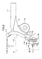
- FIG. 1 is a plan view of a left half of a torsion beam suspension for a rear wheel of an automobile; a right half has a symmetrical structure relative to a longitudinally central line of a vehicle body.
- This torsion beam suspension includes a pair of left and right trailing arms 10 extending substantially linearly in a substantially longitudinal direction of the vehicle body and a torsion beam 11 extending in a substantially lateral direction of the vehicle body and integrally joining the left and right trailing arms 10, and a gusset G is welded between an end part of the torsion beam 11 and a middle part of the trailing arm 10, the gusset G enhancing the strength of the joint therebetween.
- a cylindrical trailing arm support part 12 is welded to the front end of each trailing arm 10, and the front end of each trailing arm 10 is pivotably supported on the vehicle body in a vertically swingable manner via a rubber bush joint (not illustrated) housed in the trailing arm support part 12.
- a rear wheel W is rotatably supported on a spindle 14 fixed to a spindle support plate 13 welded to the outer end of a rear part of each trailing arm 10, and a spring seat 15 is provided so as to extend between and be joined to a middle part of the trailing arm 10 and the gusset G, the spring seat 15 supporting the lower end of a suspension spring.
- the entirety of the trailing arm 10 is formed from a hollow metal pipe; its front end portion is slightly narrowed and welded to the trailing arm support part 12, and the remaining portion (that is, the main portion) extends in a straight line up to its rear end at an angle relative to the axis of the front end portion.
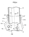
- An open end face 10a, having a closed cross-section, at the rear end of the trailing arm 10 is formed as a cut face that intersects the arm axis obliquely and is substantially vertical along the longitudinal direction of the vehicle body, and the open end face 10a is butt-welded w1 to the reverse side of the spindle support plate 13.
- a hollow pipe-shaped member formed by integrally welding to each other outer peripheral parts of an upper half and a lower half press-formed from a metal sheet may be used to form the trailing arm 10.
- the spindle support plate 13 and a structure with which it is joined to the trailing arm 10 are now explained by reference to FIG. 2 to FIG. 5 in combination.
- the spindle support plate 13 has a substantially rectangular plate main body 13M, which is larger than the open end face 10a at the rear end of the trailing arm 10 and the reverse side of which thereby abuts against the open end face 10a.
- the front side of the plate main body 13M (left-hand face in FIG. 3) is a flat mounting seat face opposite the spindle 14, which axially supports the wheel W.
- the spindle 14 includes a stepped shaft-shaped spindle main body 14a axially supporting the wheel W and a rectangular flange-shaped spindle base plate 14b formed integrally with a base of the spindle main body 14a, and the spindle base plate 14b is superimposed on the front side of the plate main body 13M of the spindle support plate 13 and welded w2 thereto.
- a drum brake back plate P which is attached to the wheel W as a brake related plate-shaped component, is superimposed on and disposed on the outer face of the spindle base plate 14b.
- Four threaded hole portions Sfu, Sfd, Sru, and Srd into which four bolts B for securing the back plate P to the plate main body 13M are respectively screwed and tightened are provided spaced from each other in the spindle base plate 14b at front, rear, upper, and lower positions relative to the spindle axis L (that is, so as to surround the axis L while longitudinally and vertically sandwiching the axis L).
- At least any one of the four threaded hole portions (the two at the upper front and upper rear in the illustrated example), that is, the threaded hole portions Sfu and Sru, are disposed at positions corresponding to the outside of the open end face 10a, and the other ones (the two at the lower front and lower rear in the illustrated example), that is, the threaded hole portions Sfd and Srd are disposed at positions corresponding to the inside of the open end face 10a. As shown in FIG.
- the spindle base plate 14b is welded w2 to the plate main body 13M via at least one part, the four corners in the illustrated example, of the outer periphery of the spindle base plate 14b (that is, portions corresponding to the four threaded hole portions Sfu, Sfd, Sru, and Srd).
- a hub portion Wh of the wheel W is rotatably fitted onto and supported by the spindle main body 14a via a bearing, and the hub portion Wh is prevented from coming off the spindle main body 14a by a spindle nut N screwed around a threaded portion of the outer end of the spindle main body 14a.
- a brake drum D of a drum brake and an inner peripheral part of the wheel W are secured together to the hub portion Wh via a plurality of bolts b, and the back plate P is provided with a brake shoe Ds that can come into pressure contact with the brake drum D and a wheel cylinder (not illustrated) that makes the brake shoe Ds operate.
- the structure with which such a wheel hub portion Wh is secured to the spindle 14 and the internal structure of the drum brake are known conventionally, and therefore will not be explained in any further detail.
- a spindle support hole 13h is formed in the plate main body 13M on an extension of the spindle axis L, and an engagement projection 14bs projectingly provided integrally with the reverse side of the spindle base plate 14b is fitted into the spindle support hole 13h, thus positioning the spindle 14 relative to the spindle plate 13.
- formed in the plate main body 13M at positions corresponding to the four threaded hole portions Sfu, Sfd, Sru, and Srd are through holes 13Mb or recess holes receiving shaft end parts of four bolts B screwed into the threaded hole portions.
- a front bent flange 13F is connected integrally to the front end part of the plate main body 13M, the front bent flange 13F extending vertically throughout substantially the whole region between upper and lower ends of the front end part of the plate main body 13M and being bent toward the inside of the vehicle body
- a rear bent flange 13R is connected integrally to the rear end part of the plate main body 13, the rear bent flange 13R extending vertically throughout substantially the whole region between upper and lower ends of the rear end part of the plate main body 13M and being bent toward the inside of the vehicle body.
- the front bent flange 13F extends forward along the outer face of the rear end part of the trailing arm 10, at least the front edge of the flange 13F is welded w3 to the outer face of the rear end part of the arm 10, and the rear bent flange 13R engages with a rear edge part of the trailing arm 10 and is welded w4 thereto.
- the front bent flange 13F is formed so as to have a substantially U-shaped cross-section by integrating together a front flange portion 13Ff, an upper flange portion 13Fu, and a lower flange portion 13Fd that abut against the outer face, the upper face, and the lower face of the rear end part of the trailing arm 10 so as to clasp the rear end part thereof.
- the front flange portion 13Ff is slightly curved so as to substantially follow the outer periphery of the rear end part of the trailing arm 10, its forward edge (that is, the front edge) apart from a central expanded portion of the front flange portion 13Ff is welded w3 to the outer face of the arm rear end part, the front edge and inner edge of the upper flange portion 13Fu are welded w3' to the upper face of the arm rear end part, and the front edge and inner edge of the lower flange portion 13Fd are welded w3" to the lower face of the arm rear end part.
- an upper bent flange 13U and a lower bent flange 13D are provided so as to be connected integrally to the upper edge and the lower edge of the plate main body 13M respectively, the upper bent flange 13U and the lower bent flange 13D corresponding to the front upper and lower threaded hole portions Sfu and Sfd respectively and each being bent toward the inside of the vehicle body, and front end sides of the upper bent flange 13U and the lower bent flange 13D are continuous as a unit with the upper flange portion 13Fu and the lower flange portion 13Fd respectively.
- An expanded tube portion 10s is formed on an upper half of the rear end part of each of the trailing arms 10, the expanded tube portion 10s protruding upward so as to pass a joining line, or the vicinity thereof, that joins the axes of the two threaded hole portions Sfu and Sru, while a top part of the open end face 10a of the arm rear end goes around the two upper front and rear threaded hole portions Sfu and Sru (that is, outside the open end face 10a) along the peripheral directions thereof.
- This expanded tube portion 10s is formed simultaneously in a step of forming a clearance shape for the above-mentioned two threaded hole portions Sfu and Sru, and in this case since the trailing arm 10 has a substantially linear pipe structure, forming of the expanded tube portion 10s is relatively easily carried out.
- the open end face 10a at the rear end of the trailing arm 10 and the plate main body 13M are welded w1 along the peripheral direction of the open end face 10a apart from a region corresponding to at least the two upper front and rear threaded hole portions Sfu and Sru (moreover, in the illustrated example, a front end part region).
- This enables the necessity for welding in the vicinity of the two threaded hole portions Sfu and Sru, which most affects the post-welding precision flatness necessary for mounting the spindle on the plate main body 13M, to be eliminated, and the occurrence of collapsing due to thermal shrinkage during cooling after welding to be prevented effectively, thus ensuring that there is sufficient precision flatness.
- the rear bent flange 13R is in intimate contact with a chamfered portion 10ar formed on the rear end part of the open end face 10a at the rear end of the trailing arm 10, and the rear edge of the chamfered portion 10ar is welded w4 to the rear bent flange 13R.
- the front bent flange 13F which extends forward along the outer face of the rear end part of the trailing arm 10 and is welded w3 to the outer face of the rear end part, is connected integrally to the front end part of the plate main body 13M of the spindle support plate 13, the rear bent flange 13R, which engages with the rear edge part of the trailing arm 10 and is welded w4 thereto, is connected integrally to the rear end part of the plate main body 13M, and the spindle base plate 14b is superimposed on and fixed (in the illustrated example, by the weld w2) to the outer face of the plate main body 13M and includes the four threaded hole portions Sfu, Sfd, Sru, and Srd arranged so as to be spaced from each other at front, rear, upper, and lower positions relative to the spindle axis L, the four bolts B for fixing the back plate P, which is a brake related plate-shaped component, being screwe
- the spindle support plate 13 to be made thin since there is no necessity for providing a threaded hole portion for a spindle-fastening bolt B to be inserted into, and even if the spindle support plate 13 is press-formed from a thin metal plate in this way, the rigidity of the front end part and the rear end part of the plate main body 13M, and in particular the support rigidity of the front and rear threaded hole portions Sfu and Sru outside the arm open end face 10a, can be enhanced, thermal deformation of the plate main body 13M due to thermal distortion when butt-welding w1 the arm open end can be suppressed effectively by the front and rear bent flanges, the welding region w1 of the arm open end can be minimized, deformation of the seat face of the thin plate main body 13M due to thermal distortion can therefore be suppressed effectively by the front and rear bent flanges 13F and 13R, and it is possible to ensure the post-welding precision flatness necessary for mounting the spindle base plate
- the spindle support plate 13 can be welded to the trailing arm 10 at a position sufficiently far forward from the spindle axis L; this can not only eliminate the influence of the above-mentioned thermal distortion but also the efficiency of transmitting a load from the spindle support plate 13 to the trailing arm 10 becomes very good, the burden imposed on the welded part w3 is lightened, the durability is improved, and the strength is increased.
- the front bent flange 13F is formed so as to have a substantially U-shaped cross-section by integrating the front flange portion 13Ff, the upper flange portion 13Fu, and the lower flange portion 13Fd and butt-welding w3, w3', and w3" them to the outer face, the upper face, and the lower face of the arm rear end part respectively, the arm rear end part is supported by being clasped stably by the front bent flange 13F.
- This enables the moment span on the joint between the front bent flange 13F and the trailing arm 10 to be enlarged in both longitudinal and vertical directions to thus reduce the support stress occurring in each welded part, thereby further improving the durability and increasing the strength.
- the flexural rigidity of the plate main body 13M can be further enhanced, and the support rigidity of the front and rear threaded hole portions Sfu and Sru outside the arm open end face 10a can be further increased.
- the spindle support plate 13, and the spindle 14 can be handled as a subassembly (small assembly), the number of components can be reduced, and the assembly efficiency of a vehicle can be enhanced.
- the above-mentioned bolt B only needs to have a length sufficient for being screwed into the threaded hole portion of the spindle base plate 14b in order to secure the brake related plate-shaped component (back plate P), it is unnecessary to specially provide a weld nut on the reverse side of the spindle support plate 13, and it is therefore possible to reduce the weight of the suspension by a corresponding amount.
- the spindle support plate 13 is directly fixed to the rear end part of the trailing arm 10 without a large bracket, it is possible to increase the rigidity of the above-mentioned subassembly (small assembly) by reducing the amount of offset between the spindle axis L and the main cross-section of the trailing arm 10.
- FIG. 6 shows .a first modification example of the first embodiment.
- This modification example is different from the first embodiment in terms of an upper bent flange 13U and a lower bent flange 13D formed integrally with the upper edge and the lower edge of a plate main body 13M respectively being formed not only in a region corresponding to two, that is, front upper and lower threaded hole portions Sfu and Sfd, but also in a long region throughout substantially the whole region in the longitudinal direction of the plate main body 13M.
- the arrangement is otherwise basically the same as that of the first embodiment.
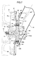
- FIG. 7 shows a second modification example of the first embodiment.
- a spindle support hole 13h is formed by burring in a substantially central part of a plate main body 13M of a spindle support plate 13, and a base shaft portion 14c projectingly provided on a back face of a spindle base plate 14b coaxially with a spindle main body 14a is press-fitted into the spindle support hole 13h.
- a small-diameter forward end portion 14ca of the base shaft portion 14c of a spindle 14 runs through an opening 10k formed on an inside wall of a rear end part of a trailing arm 10 from the inside to the outside and is fixed thereto by a weld w5.
- a second embodiment of the present invention is now explained by reference to FIG. 8 to FIG. 12. Since the basic structure of a torsion beam suspension of the second embodiment is the same as that of the first embodiment, each component is denoted by a number obtained by adding 100 to the reference numerals and symbols of the corresponding component of the first embodiment, and explanation of the basic structure is not repeated. It is mainly parts that are different from the first embodiment that are explained below.
- a spindle support plate 113 has a substantially rectangular plate main body 113M, and an open end face 110a at the rear end of a trailing arm 110 is butt-welded w11 to the rear face of the plate main body 113M.
- the surface of the plate main body 113M (left-hand face in FIG.
- At least any one of the nuts (in the illustrated example, the two at the upper front and rear), that is, Nfu and Nru, are positioned outside the open end face 110a, the other nuts Nfd and Nrd (in the illustrated example, the two at the lower front and rear) are positioned inside the open end face 110a, and each of the nuts Nfu, Nfd, Nru, and Nrd is secured to the plate main body 113M by a projection weld w12.
- a front bent flange 113F and a rear bent flange 113R having the same structure as that of the first embodiment are provided integrally with a front end part and a rear end part of the plate main body 113M respectively.
- the front bent flange 113F extends forward along the outer face of the rear end part of the trailing arm 110 and its front edge is welded w13 to the outer face of the rear end part, and the rear bent flange 113R engages with a rear edge part of the trailing arm 110 and is welded w14 thereto.
- the front bent flange 113F is formed so as to have a substantially U-shaped cross-section by integrating together a front flange portion 113Ff, an upper flange portion 113Fu, and a lower flange portion 113Fd that abut against an outer face, an upper face, and a lower face of the rear end part respectively so as to clasp the rear end part of the trailing arm 110.
- the front flange portion 113Ff is slightly bent so as to substantially follow the outer periphery of the rear end part of the trailing arm 110, the forward edge (that is, the front edge) of the front flange portion 113Ff, apart from its central expanded portion, is welded w13 to the outer face of the arm rear end part, the upper flange portion 113Fu has its front edge and inner edge welded w13' to the upper face of the arm rear end part, and the lower flange portion 113Fd has its front edge and inner edge welded w13" to the lower face of the arm rear end part.
- an upper bent flange 113U and a lower bent flange 113D are provided so as to be connected integrally to the upper edge and the lower edge of the plate main body 113M, the upper bent flange 113U and the lower bent flange 113D being bent toward the inside of a vehicle body so as to correspond to the two front upper and lower nuts Nfu and Nfd respectively, and front end sides of the upper bent flange 113U and the lower bent flange 113D are continuous as a unit with the upper flange portion 113Fu and the lower flange portion 113Fd respectively.
- An expanded tube portion 110s is formed on an upper half of the rear end part of each of the trailing arms 110, the expanded tube portion 110s protruding upward so as to pass a joining line, or the vicinity thereof, that joins the axes of the two nuts Nfu and Nru, while a top part of the open end face 110a at the arm rear end goes around the two upper front and rear nuts Nfu and Nru (that is, outside the open end face 110a) along the peripheral directions thereof.
- This expanded tube portion 110s is formed simultaneously in a step of forming a clearance shape for the above-mentioned two nuts Nfu and Nru, and in this case since the trailing arm 110 has a substantially linear pipe structure, forming of the expanded tube portion 110s is relatively easily carried out.
- the open end face 110a at the rear end of the trailing arm 110 and the plate main body 113M are welded w11 along the peripheral direction of the open end face 110a apart from at least a region corresponding to the two upper front and rear nuts Nfu and Nru (moreover, in the illustrated example, a front end part region).
- the rear bent flange 113R is in intimate contact with a chamfered portion 110ar formed in a rear end part of the open end face 110a at the rear end of the trailing arm 110, and the rear edge of the chamfered portion 110ar is welded w14 to the rear bent flange 113R.
- a spindle support hole 113h is formed in a substantially central part of the plate main body 113M through which the spindle axis L passes, the spindle support hole 113h running through from the interior to the exterior of the plate main body 113M.
- the spindle 114 includes a stepped shaft-shaped spindle main body 114a axially supporting a wheel W, a rectangular flange-shaped spindle base plate 114b formed integrally with a base of the spindle main body 114a, and a base shaft portion 114c projectingly provided on the back side of the spindle base plate 114b coaxially with the spindle main body 114a, the base shaft portion 114c being fitted into and supported by the spindle support hole 113h, and the spindle base plate 114b being superimposed on the surface of the plate main body 113M of the spindle support plate 113.
- the spindle base plate 114b is secured to the spindle support plate 113 via bolts B' that run through bolt through holes provided in the spindle base plate 114b and the plate main body 113M and are screwed into the nuts Nfu, Nfd, Nru, and Nrd.
- the effects of specially providing the front bent flange 113F and the rear bent flange 113R on the front end part and the rear end part of the plate main body 113M of the spindle support plate 113 respectively are the same as those of the first embodiment.
- the nuts Nfu, Nfd, Nru, and Nrd can be fixed to the plate main body 113M easily and appropriately by the projection weld w12, and it is possible to ensure that there is a sufficient thread length without specially machining a thread in the plate main body 113M itself, thus saving cost. Furthermore, when it is necessary to replace either of the spindle 114 or the trailing arm 110 due to wear, deformation, etc., only one thereof needs to be replaced, and the cost of replacement can be reduced by a corresponding amount.
- FIG. 13 shows a first modification example of the second embodiment.
- This modification example is different from the second embodiment only in terms of an upper bent flange 113U and a lower bent flange 113D formed integrally with the upper edge and the lower edge of a plate main body 113M being formed not only in a region corresponding to two front upper and lower nuts Nfu and Nfd but also in a long region throughout substantially the whole region in the longitudinal direction of the plate main body 113M.
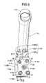
- FIG. 14 shows a second modification example of the second embodiment.
- bolts B' screwed into nuts Nfu, Nfd, Nru, and Nrd as four threaded hole portions provided spaced from each other at front, rear, upper, and lower positions relative to a spindle axis L are not used for fastening the spindle 114 onto an outer face of the spindle support plate 113 as in the first embodiment, but are used for fastening a back plate P superimposed on an outer face of a spindle support plate 113, and this back plate P forms a brake related plate-shaped component.
- a spindle support hole 113h is formed by burring in a substantially central part of a plate main body 113M, and a base shaft portion 114c projectingly provided on the back side of a spindle base plate 114b formed in a small-diameter disk shape so as to be coaxial with a spindle main body 114a is press-fitted into the spindle support hole 113h.
- a small-diameter forward end portion 114ca of the base shaft portion 114c runs through from the inside to the outside of an opening 110k formed in an inner wall of a rear end part of a trailing arm 110 and is welded w15 thereto.
- the spindle base plate 14b is secured to the spindle support plate 13 via the weld w2, but it may be secured by securing means other than welding, such as, for example, crimping or screwing.
- the spindle base plate 114b is superimposed on the spindle support plate 113 and secured by the bolt B', but also in this second embodiment and the first modification example thereof, as in the first embodiment, the spindle base plate 114b and a brake-related plate-shaped component P (e.g. a back plate or a splash plate) may be superimposed (in this case, either may be disposed on the outside), and the spindle base plate 114b and the plate-shaped component may be secured together to the spindle support plate 113 by the bolt B'.
- a brake-related plate-shaped component P e.g. a back plate or a splash plate
- the spindle base plate 114b has a small-diameter disc shape, but in this second modification example also, the spindle base plate 114b may be formed in the same rectangular shape as that of the second embodiment and the first modification example thereof, and the spindle base plate 114b and the brake related plate-shaped component P may be secured together to the spindle support plate 113 by the bolt B'.
- the spindle support holes 13h and 113h are formed by pressing or drilling, and instead of such machining the spindle support hole may be formed by burring.
Landscapes
- Engineering & Computer Science (AREA)
- Mechanical Engineering (AREA)
- Vehicle Body Suspensions (AREA)
Applications Claiming Priority (1)
| Application Number | Priority Date | Filing Date | Title |
|---|---|---|---|
| PCT/JP2005/003721 WO2006095386A1 (fr) | 2005-03-04 | 2005-03-04 | Suspension a longeron de torsion |
Publications (2)
| Publication Number | Publication Date |
|---|---|
| EP1832448A1 true EP1832448A1 (fr) | 2007-09-12 |
| EP1832448A4 EP1832448A4 (fr) | 2008-04-16 |
Family
ID=36952997
Family Applications (1)
| Application Number | Title | Priority Date | Filing Date |
|---|---|---|---|
| EP05719993A Withdrawn EP1832448A4 (fr) | 2005-03-04 | 2005-03-04 | Suspension a longeron de torsion |
Country Status (4)
| Country | Link |
|---|---|
| US (1) | US20070290474A1 (fr) |
| EP (1) | EP1832448A4 (fr) |
| CN (1) | CN100589999C (fr) |
| WO (1) | WO2006095386A1 (fr) |
Cited By (4)
| Publication number | Priority date | Publication date | Assignee | Title |
|---|---|---|---|---|
| DE102008021155A1 (de) * | 2008-04-28 | 2009-10-29 | Volkswagen Ag | Verfahren zur Herstellung einer Torsionskurbelachse in Schweißkonstruktion sowie Torsionskurbelachse |
| EP2221196A1 (fr) * | 2009-02-24 | 2010-08-25 | Benteler Automobiltechnik GmbH | Essieu semi-rigide et son procédé de fabrication |
| FR2972961A1 (fr) * | 2011-03-24 | 2012-09-28 | Peugeot Citroen Automobiles Sa | Support de montage de roue de vehicule |
| EP3202602A4 (fr) * | 2014-10-03 | 2018-06-20 | F-Tech Inc. | Plaque d'extrémité pour élément de suspension |
Families Citing this family (14)
| Publication number | Priority date | Publication date | Assignee | Title |
|---|---|---|---|---|
| US20060158023A1 (en) * | 2005-01-14 | 2006-07-20 | The Boler Company | Continuous radius axle and fabricated spindle assembly |
| US7556272B2 (en) * | 2005-09-06 | 2009-07-07 | Gm Global Technology Operations, Inc. | Twist axle suspensions |
| KR100953320B1 (ko) * | 2008-07-25 | 2010-04-20 | 현대자동차주식회사 | 토션 빔 액슬 타입 현가장치의 스핀들 브라켓 |
| WO2012011482A1 (fr) * | 2010-07-23 | 2012-01-26 | 本田技研工業株式会社 | Dispositif de suspension de type barre de torsion |
| JP5691094B2 (ja) * | 2011-01-24 | 2015-04-01 | ダイハツ工業株式会社 | 車両用サスペンション構造 |
| MX2013007598A (es) * | 2011-01-28 | 2014-02-17 | Hendrickson Usa Llc | Ensamblaje de soporte de montaje elestico para vehiculos de servicio pesado. |
| DE202011103222U1 (de) * | 2011-07-08 | 2012-10-11 | Al-Ko Kober Ag | Achse |
| DE102014107896A1 (de) * | 2014-06-04 | 2015-12-17 | Benteler Automobiltechnik Gmbh | Flanschplatte zum Anbinden einer Verbundlenkerachse an ein Radlager |
| CN105966187A (zh) * | 2016-07-08 | 2016-09-28 | 奇瑞汽车股份有限公司 | 一种车辆后扭转梁总成 |
| CN107089110A (zh) * | 2017-04-17 | 2017-08-25 | 广西大学 | 一种汽车扭梁悬架后轴总成 |
| WO2019191567A1 (fr) * | 2018-03-29 | 2019-10-03 | Magna International Inc. | Ensemble essieu de torsion de véhicule |
| DE102018120479B4 (de) * | 2018-08-22 | 2024-07-11 | Benteler Automobiltechnik Gmbh | Verfahren zur Herstellung einer Achskomponente |
| JP7214706B2 (ja) * | 2020-12-15 | 2023-01-30 | 本田技研工業株式会社 | ハブブラケット構造 |
| JP2023141559A (ja) * | 2022-03-24 | 2023-10-05 | 本田技研工業株式会社 | リヤサスペンション構造 |
Family Cites Families (33)
| Publication number | Priority date | Publication date | Assignee | Title |
|---|---|---|---|---|
| US4165098A (en) * | 1977-11-28 | 1979-08-21 | Chrysler Corporation | Rear suspension apparatus for a motor vehicle |
| US5507518A (en) * | 1993-12-24 | 1996-04-16 | Yorozu Corporation | Torsion beam type suspension and method for production thereof |
| JPH0737719U (ja) * | 1993-12-24 | 1995-07-11 | 株式会社ヨロズ | トーションビーム式サスペンション |
| JP3419135B2 (ja) * | 1994-03-15 | 2003-06-23 | トヨタ自動車株式会社 | 車輌用サスペンション |
| DE19520520A1 (de) * | 1994-06-16 | 1995-12-21 | Volkswagen Ag | Biegesteifer Lenker aus Rohrmaterial |
| JP3546564B2 (ja) * | 1995-03-24 | 2004-07-28 | トヨタ自動車株式会社 | ツイストビーム式サスペンション |
| DE19649076B4 (de) * | 1996-11-27 | 2006-10-05 | Benteler Ag | Verfahren zur Herstellung einer Verbundlenkerachse für Kraftfahrzeuge und Verbundlenkerachse |
| JPH10236123A (ja) * | 1997-02-27 | 1998-09-08 | Toyota Motor Corp | トーションビーム式サスペンション |
| FR2761304B1 (fr) * | 1997-03-28 | 1999-06-18 | Peugeot | Train de roues arriere pour vehicule automobile a traverse deformable en torsion |
| DE29720207U1 (de) * | 1997-11-14 | 1998-01-02 | Benteler Ag, 33104 Paderborn | Verbundlenkerachse für Kraftfahrzeuge |
| JPH11208232A (ja) * | 1998-01-30 | 1999-08-03 | Daihatsu Motor Co Ltd | サスペンションの構造 |
| DE19840134A1 (de) * | 1998-09-03 | 2000-03-09 | Volkswagen Ag | Verbundlenker-Hinterachse für ein Kraftfahrzeug |
| JP3551039B2 (ja) * | 1998-09-25 | 2004-08-04 | トヨタ自動車株式会社 | トーションビーム式サスペンション |
| US6086162A (en) * | 1998-12-14 | 2000-07-11 | General Motors Corporation | Motor vehicle rear axle and method |
| JP2000229581A (ja) * | 1999-02-10 | 2000-08-22 | Nissan Motor Co Ltd | サスペンション取付部構造 |
| FR2805776B1 (fr) * | 2000-03-02 | 2003-06-27 | Michelin & Cie | Essieu souple pour vehicule automobile, a dispositif anti- roulis perfectionne |
| FR2807000A1 (fr) * | 2000-03-31 | 2001-10-05 | Michelin & Cie | Procede d'assemblage d'un systeme de suspension |
| JP2002120534A (ja) * | 2000-10-16 | 2002-04-23 | Mitsubishi Motors Corp | リヤサスペンション |
| DE20101602U1 (de) * | 2001-01-31 | 2001-04-05 | Benteler Automobiltechnik GmbH & Co. KG, 33104 Paderborn | Verbundlenkerachse |
| DE10116748B4 (de) * | 2001-04-04 | 2006-10-05 | Benteler Automobiltechnik Gmbh | Querstrebe für eine Verbundlenkerachse |
| JP4066715B2 (ja) * | 2002-05-28 | 2008-03-26 | トヨタ自動車株式会社 | 車両用サスペンションビーム |
| CN100387449C (zh) * | 2002-07-04 | 2008-05-14 | 本田技研工业株式会社 | 扭矩梁式悬架 |
| JP4093548B2 (ja) * | 2002-07-09 | 2008-06-04 | 株式会社エフテック | トーションビーム式サスペンション |
| US6827360B2 (en) * | 2002-10-24 | 2004-12-07 | Arvinmeritor Technology, Llc | One-piece trailing arm section |
| ITTO20020959A1 (it) * | 2002-11-07 | 2004-05-08 | Sistemi Sospensioni Spa | Ponte torcente per la sospensione posteriore di un |
| JP4140462B2 (ja) * | 2003-06-27 | 2008-08-27 | トヨタ自動車株式会社 | トーションビーム式サスペンション装置 |
| JP4270986B2 (ja) * | 2003-09-05 | 2009-06-03 | 株式会社エフテック | トーションビーム式サスペンション |
| KR20050036408A (ko) * | 2003-10-16 | 2005-04-20 | 현대모비스 주식회사 | 토션 빔 액슬 서스펜션 |
| KR20060014143A (ko) * | 2004-08-10 | 2006-02-15 | 현대모비스 주식회사 | 후방 현가장치의 스핀들브래킷 |
| EP1707409B1 (fr) * | 2005-03-31 | 2009-12-02 | Mazda Motor Corporation | Essieu arrière du type à traverse déformable en torsion |
| JP4193837B2 (ja) * | 2005-11-04 | 2008-12-10 | トヨタ自動車株式会社 | トレーリング・アーム式サスペンション構造及びアクスルキャリア |
| JP2007153254A (ja) * | 2005-12-08 | 2007-06-21 | Toyota Motor Corp | トレーリング・アーム式サスペンション構造 |
| US7284765B1 (en) * | 2006-12-01 | 2007-10-23 | E. Tech Incorporation | Torsion beam suspension |
-
2005
- 2005-03-04 WO PCT/JP2005/003721 patent/WO2006095386A1/fr not_active Ceased
- 2005-03-04 EP EP05719993A patent/EP1832448A4/fr not_active Withdrawn
- 2005-03-04 CN CN200580045588A patent/CN100589999C/zh not_active Expired - Fee Related
- 2005-03-04 US US11/791,328 patent/US20070290474A1/en not_active Abandoned
Cited By (5)
| Publication number | Priority date | Publication date | Assignee | Title |
|---|---|---|---|---|
| DE102008021155A1 (de) * | 2008-04-28 | 2009-10-29 | Volkswagen Ag | Verfahren zur Herstellung einer Torsionskurbelachse in Schweißkonstruktion sowie Torsionskurbelachse |
| EP2221196A1 (fr) * | 2009-02-24 | 2010-08-25 | Benteler Automobiltechnik GmbH | Essieu semi-rigide et son procédé de fabrication |
| FR2972961A1 (fr) * | 2011-03-24 | 2012-09-28 | Peugeot Citroen Automobiles Sa | Support de montage de roue de vehicule |
| EP3202602A4 (fr) * | 2014-10-03 | 2018-06-20 | F-Tech Inc. | Plaque d'extrémité pour élément de suspension |
| US10543728B2 (en) | 2014-10-03 | 2020-01-28 | F-Tech Inc. | End plate of suspension member |
Also Published As
| Publication number | Publication date |
|---|---|
| WO2006095386A1 (fr) | 2006-09-14 |
| CN100589999C (zh) | 2010-02-17 |
| EP1832448A4 (fr) | 2008-04-16 |
| US20070290474A1 (en) | 2007-12-20 |
| CN101094772A (zh) | 2007-12-26 |
Similar Documents
| Publication | Publication Date | Title |
|---|---|---|
| EP1832448A1 (fr) | Suspension a longeron de torsion | |
| US6398262B1 (en) | Modular subframe assembly for a motor vehicle | |
| US7980576B2 (en) | Vehicular suspension arm | |
| US20080029988A1 (en) | Cast trailing arm assembly for trailer suspension | |
| US20110285102A1 (en) | Vehicular l-type suspension arm | |
| EP1266773A2 (fr) | Structure de chassis pour véhicule automobile | |
| JPH06171545A (ja) | 自動車用ステアリングナックルアセンブリ | |
| US8272656B2 (en) | Frame structure of a vehicle | |
| US6648351B1 (en) | Cast aluminum rear subframe control arm articulations | |
| US6547268B2 (en) | Motor vehicle suspension system | |
| JP4662041B2 (ja) | 車輌の揺動アーム取付構造 | |
| US11090994B2 (en) | Front lower arm | |
| US20030168296A1 (en) | Vehicle damper assembly and method | |
| US5664847A (en) | Cast tube-yoke bracket assembly | |
| US8123239B2 (en) | Knuckle and method of manufacturing knuckle | |
| JP4270986B2 (ja) | トーションビーム式サスペンション | |
| US6799811B1 (en) | Steer axle with kingpin boss | |
| JP2006232180A (ja) | トーションビーム式サスペンション | |
| US7188850B2 (en) | Beam axle suspension with diagonal link | |
| US20020121758A1 (en) | Vehicle steering assembly | |
| JP3128678B2 (ja) | ショックアブソーバの取り付け構造 | |
| JP2004330928A (ja) | トーションビーム式サスペンション構造 | |
| JPH11334332A (ja) | フロントサスペンション | |
| JP2010089601A (ja) | トーションビーム式サスペンションのアライメント調整機構 | |
| JP2000006831A (ja) | タイロッドとタイロッドエンドの取付構造 |
Legal Events
| Date | Code | Title | Description |
|---|---|---|---|
| PUAI | Public reference made under article 153(3) epc to a published international application that has entered the european phase |
Free format text: ORIGINAL CODE: 0009012 |
|
| 17P | Request for examination filed |
Effective date: 20070521 |
|
| AK | Designated contracting states |
Kind code of ref document: A1 Designated state(s): DE FR GB |
|
| DAX | Request for extension of the european patent (deleted) | ||
| RBV | Designated contracting states (corrected) |
Designated state(s): DE FR GB |
|
| A4 | Supplementary search report drawn up and despatched |
Effective date: 20080319 |
|
| RIC1 | Information provided on ipc code assigned before grant |
Ipc: B60G 21/05 20060101AFI20080313BHEP |
|
| STAA | Information on the status of an ep patent application or granted ep patent |
Free format text: STATUS: THE APPLICATION IS DEEMED TO BE WITHDRAWN |
|
| 18D | Application deemed to be withdrawn |
Effective date: 20080618 |