EP1832723B1 - Commande de soupape pour régler la levée des soupapes dans un moteur à combustion interne - Google Patents
Commande de soupape pour régler la levée des soupapes dans un moteur à combustion interne Download PDFInfo
- Publication number
- EP1832723B1 EP1832723B1 EP07107909A EP07107909A EP1832723B1 EP 1832723 B1 EP1832723 B1 EP 1832723B1 EP 07107909 A EP07107909 A EP 07107909A EP 07107909 A EP07107909 A EP 07107909A EP 1832723 B1 EP1832723 B1 EP 1832723B1
- Authority
- EP
- European Patent Office
- Prior art keywords
- rotary drive
- hydraulic rotary
- stator
- rotor
- adjusting
- Prior art date
- Legal status (The legal status is an assumption and is not a legal conclusion. Google has not performed a legal analysis and makes no representation as to the accuracy of the status listed.)
- Expired - Lifetime
Links
- 238000002485 combustion reaction Methods 0.000 title description 4
- 230000005540 biological transmission Effects 0.000 description 7
- 239000000969 carrier Substances 0.000 description 3
- 230000006835 compression Effects 0.000 description 3
- 238000007906 compression Methods 0.000 description 3
- 239000000446 fuel Substances 0.000 description 3
- 238000010276 construction Methods 0.000 description 2
- 230000001419 dependent effect Effects 0.000 description 1
- 238000006073 displacement reaction Methods 0.000 description 1
- 239000012530 fluid Substances 0.000 description 1
- 238000002347 injection Methods 0.000 description 1
- 239000007924 injection Substances 0.000 description 1
- 238000004519 manufacturing process Methods 0.000 description 1
Images


Classifications
-
- F—MECHANICAL ENGINEERING; LIGHTING; HEATING; WEAPONS; BLASTING
- F01—MACHINES OR ENGINES IN GENERAL; ENGINE PLANTS IN GENERAL; STEAM ENGINES
- F01L—CYCLICALLY OPERATING VALVES FOR MACHINES OR ENGINES
- F01L13/00—Modifications of valve-gear to facilitate reversing, braking, starting, changing compression ratio, or other specific operations
- F01L13/0015—Modifications of valve-gear to facilitate reversing, braking, starting, changing compression ratio, or other specific operations for optimising engine performances by modifying valve lift according to various working parameters, e.g. rotational speed, load, torque
- F01L13/0021—Modifications of valve-gear to facilitate reversing, braking, starting, changing compression ratio, or other specific operations for optimising engine performances by modifying valve lift according to various working parameters, e.g. rotational speed, load, torque by modification of rocker arm ratio
- F01L13/0026—Modifications of valve-gear to facilitate reversing, braking, starting, changing compression ratio, or other specific operations for optimising engine performances by modifying valve lift according to various working parameters, e.g. rotational speed, load, torque by modification of rocker arm ratio by means of an eccentric
-
- F—MECHANICAL ENGINEERING; LIGHTING; HEATING; WEAPONS; BLASTING
- F01—MACHINES OR ENGINES IN GENERAL; ENGINE PLANTS IN GENERAL; STEAM ENGINES
- F01L—CYCLICALLY OPERATING VALVES FOR MACHINES OR ENGINES
- F01L1/00—Valve-gear or valve arrangements, e.g. lift-valve gear
- F01L1/34—Valve-gear or valve arrangements, e.g. lift-valve gear characterised by the provision of means for changing the timing of the valves without changing the duration of opening and without affecting the magnitude of the valve lift
- F01L1/344—Valve-gear or valve arrangements, e.g. lift-valve gear characterised by the provision of means for changing the timing of the valves without changing the duration of opening and without affecting the magnitude of the valve lift changing the angular relationship between crankshaft and camshaft, e.g. using helicoidal gear
- F01L2001/34486—Location and number of the means for changing the angular relationship
- F01L2001/34493—Dual independent phasing system [DIPS]
-
- F—MECHANICAL ENGINEERING; LIGHTING; HEATING; WEAPONS; BLASTING
- F01—MACHINES OR ENGINES IN GENERAL; ENGINE PLANTS IN GENERAL; STEAM ENGINES
- F01L—CYCLICALLY OPERATING VALVES FOR MACHINES OR ENGINES
- F01L2305/00—Valve arrangements comprising rollers
-
- F—MECHANICAL ENGINEERING; LIGHTING; HEATING; WEAPONS; BLASTING
- F01—MACHINES OR ENGINES IN GENERAL; ENGINE PLANTS IN GENERAL; STEAM ENGINES
- F01L—CYCLICALLY OPERATING VALVES FOR MACHINES OR ENGINES
- F01L2800/00—Methods of operation using a variable valve timing mechanism
- F01L2800/08—Timing or lift different for valves of different cylinders
Definitions
- the invention relates to a valve control for adjusting the stroke of valves in motor vehicles according to the preamble of claim 1.
- valve controls that are used in gasoline engines and the valve strokes vary continuously to reduce fuel consumption.
- the valve controls control the valve lift in a performance-dependent manner, so that only that amount of fuel is injected into the combustion chamber of the cylinder, which is required for the instantaneous power requirement.
- an electric motor is provided, whose pinion cooperates with a setting wheel which sits on an adjusting shaft. By means of this adjusting the transmission geometry between the camshaft and the valve is changed, so that different valve strokes can be adjusted.
- this valve control is extremely complicated and therefore expensive to manufacture.
- the invention has the object of providing the generic valve control in such a way that the valve lift can be easily changed in a cost effective manner.
- the adjusting shaft is rotated by the hydraulic drive so that the valve lift is adjusted in dependence on the currently required power of the engine.
- the valve control according to the invention preferably operates fully variable, so that within the adjustment range any desired valve lift can be adjusted.
- the hydraulic drive can be implemented easily and inexpensively and is easy to use.
- valve controls described below allow fully variable control of the stroke of injection valve valves.
- the inlet valves are opened more or less wide, so that only that amount of air is sucked into the combustion chamber of the engine, which is required for the instantaneous power requirement.
- the corresponding amount of fuel is supplied in a known manner the amount of air.
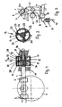
- the valve control according to the Fig. 1 to 3 has an adjusting shaft 1, on the rotatable cam 2 are provided. They act on a two-armed intermediate lever 3, one arm 5 rests by means of a roller 4 on the associated cam 2 and with its other arm 6 on a roller 8 of a roller lever 7.
- the intermediate lever 3 also carries a further roller 60 which bears against the adjusting shaft 1.
- the camshaft 61 can be seen, the cam 62 rests against a roller 63 of the intermediate lever 3.
- the cam 62 of the camshaft 61 of the intermediate lever 3 is pivoted back and forth in a known manner, being pivoted about the arm 6 of the roller lever 7 and thereby a valve stem 10 against the force of at least one compression spring 11 is moved.
- the lower (not shown) end of the valve stem 10 carries the valve, with which the inlet opening is closed in the combustion chamber of the engine cylinder.
- the valve stem 10 is displaced by the roller lever 7 against the force of at least one compression spring 11 when the valve is to be opened.
- the compression spring 11 ensures that the valve is pushed back with a corresponding position of the roller lever 7 in its closed position.
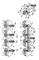
- the adjusting shaft 1 is coupled to a rotary drive 12 with which the adjusting shaft 1 is limitedly rotatable. He has a cylindrical stator 13 ( Fig. 2 ), whose two end faces are closed by cover plates 14, 15. In the stator 13, two rotors 16 and 17 are housed, of which the rotor 16 is rotatably connected to the adjusting shaft 1. The other rotor 17 is seated on an axis 18 which is aligned with the adjusting shaft 1 and is mounted in the cylinder head 19.
- the rotors 16, 17 On the inner wall of the stator 13 are radially inwardly wings 20 (FIG. Fig. 2 ), which are at angular intervals of 120 ° to each other.
- the rotors 16, 17 have a cylindrical base body 21, 22, the axis of which coincides with the axis of the stator 13 and project from the radially outward wing 23. These wings 23 also have an angular distance of 120 ° to each other.
- the rotors 16, 17 abut with the end faces of the wings 23 on the inner wall of the stator 13.
- the wings 20 of the stator 13 in turn abut against the outer wall of the cylindrical base body 21, 22.
- FIG. 2 shows, in each case a vane 23 of the rotors 16, 17 between two vanes 20 of the stator 13.
- the wings 23 of the rotors 16, 17 are acted upon in a known manner with hydraulic medium, by (not shown) holes in the spaces 24 of the stator 13th arrives.
- the wings 23 of the rotors 16, 17 can be acted upon on both sides with pressure medium, so that the rotors 16, 17 in the clockwise and counterclockwise direction relative to the stator 13 can be rotated.
- the two rotors 16, 17 are arranged coaxially with each other, but have no connection with each other.
- the stator 13 has the corresponding pressure chambers 24 for both rotors 16, 17 Fig. 1 shows, from the inner wall of the stator 13 in half the length of an annular wall 25 from which has a central passage opening 26. In it protrude from both sides tapered portions of the main body 21, 22 of the rotors 16, 17.
- the annular wall 25 is sealingly connected to the edge of the through hole 26 at the tapered end portions of the main body 21, 22 of the rotors 16, 17.
- the main body 21, 22, as Fig. 1 shows, on the mutually facing inner sides of the annular wall 25 and the cover plates 14, 15 sealingly.
- the rotor 16 is formed integrally with the adjusting shaft 1. But it can also be connected as a separate component to the adjusting shaft 1.
- the adjusting shaft 1 projects in a sealed manner through the cover disk 14.
- the rotor 17 projects with a tapered end portion 27 sealed by the cover plate 15 and is located on the front side on a wall of the cylinder head 19 at.
- the rotor 17 has a central passage opening into which the axle 18 is inserted.
- the two rotors 16, 17 are rotated independently, since they are housed with their wings 23 in the separate spaces 24 of the stator 13.
- the cover plates 14, 15 are fastened with screws 28, 29 releasably attached to the annular wall 25.
- the rotors 16, 17 can be rotated so far about their axes until their wings 23 come to rest on the wings 20 of the stator 13.
- the maximum displacement angle 30 of the rotors 16, 17 is 90 °.
- the adjusting shaft 1 can be rotated a maximum of 180 °.
- the pressure chambers 24 for the two rotors 16, 17 are each acted upon by hydraulic medium.
- the shaft-side rotor 16 is in the starting position with its wings 23 on the wings 20 of the stator 13 at.
- the vanes 23 of the other rotor 17 also abut against the stator vanes 20.
- both rotors 16, 17 are rotated against each other so that their wings rest on different stator blades 20, seen in the axial direction of the rotary drive 12.
- the pressure chambers 24 for the stator 16 are first held under pressure with the hydraulic medium, so that the rotor blades 23 bear against the stator vanes 20 under the pressure of the hydraulic medium.
- the hydraulic medium is introduced under pressure so that the stator 12 is rotated relative to the rotor 17.
- the other rotor 16 is so with his wings 23 on the stator vanes 20 that the stator 12 entrains this rotor 16 during the relative rotation.
- the adjusting shaft 1 is rotated about its axis.
- the relative rotation between the stator 5 and the rotor 17 can take place, the wings 23 of the rotor 17 are acted upon on one side with the hydraulic medium pressure, while the limited from the other side of the rotor blade 23 part of the respective pressure chamber 24 is depressurized.
- the hydraulic medium is kept under pressure in such a way that this stop position is maintained.
- the hydraulic control for the rotor 16 is switched so that now the rotor 16 can rotate relative to the stator 12.
- the rotor blades 23 are loaded on one side with the pressurized hydraulic medium, while the limited from the other side of the rotor blades 23 part of the pressure chambers 24 is depressurized.
- the adjusting shaft 1 is rotated twice by 90 °, so a total of 180 ° maximum about its axis.
- the roller lever 7 is pivoted so far back that the valve stem 10 is not actuated.
- the intermediate lever 3 counterclockwise in Fig. 3 pivoted.
- the roller lever 7 is also pivoted counterclockwise. Since the arm 9 of the roller lever 7 acts on the valve stem 10, depending on the angle of rotation of the adjusting shaft 1, the valve stem 10 is moved more or less far down and thus set the stroke of the valve according to the power requirement.
- the intake valves when the motor vehicle engine is switched off, can be returned to their initial position.
- the inlet valves in this case go back to a position in which they release the smallest inlet opening.
- the described fully variable valve control is inexpensive and also simple in construction.
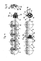
- Fig. 4 shows that with the adjustment shaft 1 and the rotary drive 12 a plurality of intake valves can be actuated simultaneously. On the adjusting shaft 1 each sit at a distance a plurality of cams 2, in each case via the intermediate drive according to Fig. 3 act on the corresponding valve stem. With the single rotary drive 12, eight cams 2 can be actuated in the exemplary embodiment, which act on corresponding valve shafts and, depending on the rotational position of the adjusting shaft 1, control the stroke of the valve.
- the adjusting shaft 1 sit on the according to the previous embodiment eight cams 2, no longer from one end, but rotatably driven in half the length.
- the adjusting shaft 1 has in the embodiment in half a length circumferential outer toothing 31, in which a rack 32 of the rotary drive 12a engages.
- the rack 32 is seated on a piston rod 33 which protrudes from a cylinder 34.
- the piston rod 33 carries within the cylinder 34, a piston 35 which is sealed in the cylinder 34 by means of hydraulic fluid displaced.
- the adjusting shaft 1 is rotated via the rack 32 in the corresponding direction.
- the corresponding valve stem is adjusted, thus adjusting the stroke of the inlet valve.
- This embodiment is characterized by its constructive simplicity.
- the rack and pinion drive ensures an exact stepless rotation of the adjusting shaft 1, so that the stroke of the intake valves can be adjusted according to continuously.
- a separate rotary drive 12a is provided, which according to the embodiment according to the FIGS. 5 and 6 is trained. Accordingly, this fully variable valve control four Verstellwellen 1, each with two cams 2.
- the intake valves can be set independently variable by the respective adjustment shaft 1 is rotated with the rotary drive 12a to the desired extent about its axis.
- the rotary actuators 12a are supplied independently with hydraulic medium, so that a trouble-free and reliable adjustment of the respective inlet valves is ensured.
- the drive 12b has a coarse adjustment device 36 and fine adjustment means 37.
- the coarse adjustment device 36, the fine adjustment means 37, which for each inlet valve according to the embodiment of Fig. 7 are provided individually, operated together. With the fine adjustment 37 then the individual adjustment shafts 1 can be adjusted to the required extent fine to individually adjust the stroke of the intake valves.
- the coarse adjustment device 36 has a drive 38, with which an intermediate shaft 39 can be rotatably driven. It lies parallel to the adjusting shafts 1 lying in alignment with each other and, in the region of a toothed rack 40, has external toothing 41 in which the toothed rack 40 engages. It sits on the end of a piston rod 43 protruding from a cylinder 42, which carries at the other end a piston 44, which is sealed in the cylinder 42. By acting on the piston 44 with a hydraulic medium, the piston rod 43 can be extended and retracted so that the intermediate shaft 39 can be rotated via the rack 40 in the desired direction.
- intermediate shaft 39 carriers 45 can be moved, which are formed in the form of a rack and with a corresponding external toothing 46 of the intermediate shaft 39 into engagement are.
- the carriers 45 which are assigned to the intake valves are of identical design and have a pressure chamber 47 in which a piston 48 is displaceable. He sits on the free end of a piston rod 49, which protrudes from the carrier 45 and carries a rack 50. It is in engagement with the external toothing 31 of the associated adjusting shaft 1.
- the intermediate shaft 39 is first rotated about its axis, whereby the carrier 45 engaged with it are moved depending on the direction of rotation in the direction of the adjusting shafts 1 or away from them.
- the valve stems 10 of the intake valves can be adjusted independently of each other in their exact position with the fine adjustment 37, so that the various intake valves run their own optimal stroke.
- the piston rods 49 of the carrier 45 are extended and retracted, whereby the adjustment shafts 1 are rotated about their axes via the racks 50 in the manner described.
- the intermediate lever 3 ( Fig. 3 ) pivoted in the manner described, whereby the roller lever 7 are pivoted accordingly.
- the valve stems 10 of the intake valves are shifted to their required position.
- the fine adjustment means 37 the intake valves can be adjusted so that knocking of the engine does not occur.
- the embodiment according to the FIGS. 11 and 12 is essentially the same design as the embodiment of the Fig. 8 to 10 , Only the drive 12c has a different configuration than in the previous embodiment.
- This drive 12 c has the same construction as the drive 12 according to the Fig. 1 to 3 ,
- the rotor 16 is provided at one end of the intermediate shaft 39, advantageously integrally formed with it.
- the drive 12c is otherwise the same design as the rotary drive 12 according to the Fig. 1 to 3 , With the two rotors 16, 17 in the stator 13, the intermediate shaft 39 can be rotated a maximum of 180 ° about its axis.
- the drive 12d is provided to drive the adjusting shaft 1. He has the cylindrical stator 13 in which a rotor 17 is rotatably mounted. He sits on the axle 18 which is mounted in the cylinder head 19 ( Fig. 13 ). In the pressure chambers 24 of the stator 13, the hydraulic medium is introduced. Thereby, the stator 13 is rotated relative to the rotor 17 in the manner described.
- the stator 13 carries on its outer casing a toothing 51 which is in engagement with an external toothing 52 of the adjusting shaft 1.
- the adjusting shaft 1 is rotated to the required extent.
- the angle of rotation of the stator 13 is only 90 °.
- the transmission ratio between the teeth 51 of the stator 13 and the external teeth 52 of the adjusting shaft 1 is selected so that the adjusting shaft rotates at a rotational angle of 90 ° of the stator 13 by 180 °.
- each adjusting shaft 1 is associated with a rotary drive 12e. He is the same as the rotary drive 12d according to the Fig. 13 and 14 .
- the adjusting shafts 1 can be driven independently of one another to the required extent rotatably.
- the valve stems of the intake valves of the engine cylinders Z can therefore be moved independently of each other optimally.
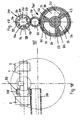
- the 17 to 19 shows a rotary drive 12f, similar to the embodiment of the Fig. 8 to 10 a coarse adjustment means 36f and fine adjustment 37f for the individual adjustment shafts 1 has.
- the coarse adjustment device 36 f has the stator 13, in which the rotor 17 is housed, which sits on the axis 18. It is stored in the cylinder head 19.
- the stator 13 has the external teeth 51.
- the hydraulic medium is introduced into the pressure chambers 24 of the stator 13 so that the stator 13 is rotated relative to the rotor 17.
- the maximum angle of rotation of the stator 13 is 90 ° in the embodiment.
- each pivot motor 53 has an outer ring 54 (FIG. Fig. 19 ), which is provided with an outer toothing 55, with which the outer ring 54 in the external teeth 52 of the intermediate shaft 39 engages. From the inner wall of the outer ring 54 are radially inwardly from wings 56 which abut with their end faces on a cylindrical base body 57 of a rotor 58. He has radially outwardly directed wings 59 which abut with their end faces on the inner wall of the outer ring 54.
- the rotor 58 can be rotated by a small angle of rotation within the outer ring 54 until its wings 59 come to rest on the side surfaces of one of the adjacent vanes 56 of the outer ring 54.
- the rotor 58 is rotatably connected to the respective adjusting shaft 1.
- hydraulic medium is introduced under pressure, so that the relative rotation of the rotor 58 relative to the outer ring 54 can be performed.
- each cylinder has only one inlet valve.
- valve controls have been described with reference to the embodiments for controlling the lift of intake valves.
- the valve controls can of course also be used for exhaust valves in the same way to change their stroke accordingly.
- the adjusting shaft 1 is provided with cams 2 respectively.
- the adjusting shaft 1 can also be an eccentric shaft, for example, which carries no cams in this case. It is essential for the adjustment that during their rotation a transverse or radial component is generated, which is exploited to move the valve stem 10 in the desired mass via the transmission chain.
- the transmission chain does not have to be as exemplified in Fig. 3 is shown formed by mechanical components, but may for example also be a hydraulic transmission chain. It only has to be ensured that the normal stroke of the valve stem 10 generated by the camshaft of the engine can be varied by the adjusting shaft 1.
Landscapes
- Engineering & Computer Science (AREA)
- Mechanical Engineering (AREA)
- General Engineering & Computer Science (AREA)
- Valve Device For Special Equipments (AREA)
- Valve-Gear Or Valve Arrangements (AREA)
- Control Of Throttle Valves Provided In The Intake System Or In The Exhaust System (AREA)
- Output Control And Ontrol Of Special Type Engine (AREA)
Claims (20)
- Entraînement rotatif hydraulique (12, 12c) d'une commande de soupape d'un moteur à combustion interne avec un stator cylindrique (13) dans lequel deux rotors (16, 17) sont disposés, parmi lesquels un des rotors (16) est relié fixement sans rotation à un arbre de réglage (1) tandis que le deuxième rotor (17) repose sur un axe (18) de façon alignée par rapport à l'arbre de réglage (1) et est disposé contre la tête de vérin (19).
- Entraînement rotatif hydraulique (12, 12c) selon la revendication 1, caractérisé en ce que des cames (2) fixes sans rotation sont prévues sur l'arbre de réglage (1) à relier.
- Entraînement rotatif hydraulique (12, 12c) selon La revendication 1 ou 2, caractérisé en ce que des pales (20) ressortent de La paroi intérieure du stator (13), entre lesquelles reposent radialement des pales (23) saillant hors d'un corps de base (21, 22), notamment d'un corps de base (21, 22) cylindrique, du rotor (16, 17), et que de façon avantageuse les pales de rotor (23) et les pales de stator (20) peuvent tourner l'une par rapport à l'autre de façon limitée, l'axe du stator (13) et du rotor (16, 17) coïncidant notamment.
- Entraînement rotatif hydraulique (12, 12c) selon l'une quelconque des revendications précédentes, caractérisé en ce que les rotors (16, 17) disposés dans le stator (13) sont deux rotors (16, 17) connexes dans le plan axial séparés l'un par rapport à l'autre, les rotors (16, 17) présentant notamment un axe identique.
- Entraînement rotatif hydraulique (12, 12c) selon La revendication 4, caractérisé en ce que les rotors (16, 17) sont disposés dans des espaces (24) séparés l'un de l'autre.
- Entraînement rotatif hydraulique (12, 12c) selon l'une quelconque des revendications précédentes, caractérisé en ce que les rotors (16, 17) peuventtourner indépendamment l'un de l'autre.
- Entraînement rotatif hydraulique (12, 12c) selon l'une quelconque des revendications précédentes, caractérisé en ce que le stator (13) peut tourner de façon limitée par rapport à l'autre rotor (17) par exercice d'une pression, en engrenant le rotor (16) situé côté arbre de réglage.
- Entraînement rotatif hydraulique (12, 12c) selon l'une quelconque des revendications précédentes, caractérisé en ce que le rotor (16) situé côté arbre de réglage peut tourner de façon limitée par rapport au stator (13) par exercice d'une pression.
- Entraînement rotatif hydraulique (12, 12c) selon l'une quelconque des revendications 1 à 8, caractérisé en ce que l'arbre de réglage (1) à raccorder comporte au moins une, de façon avantageuse plusieurs cames (2) pour plusieurs soupapes.
- Entraînement rotatif hydraulique (12, 12c) selon l'une quelconque des revendications 1 à 9, caractérisé en ce que chacun des arbres de réglage (1) à raccorder comporte deux cames (2) pour deux soupapes.
- Entraînement rotatif hydraulique (12, 12b, 12f), notamment selon l'une quelconque des revendications 1 à 10, caractérisé en ce que l'entraînement hydraulique (12, 12b, 12f) comporte un dispositif de réglage grossier (36, 36f) et au moins un dispositif de réglage fin (37, 37f).
- Entraînement rotatif hydraulique (12, 12b, 12f) selon la revendication 11, caractérisé en ce que te dispositif de réglage grossier (36, 36f) comporte un arbre intermédiaire (39) via lequel un arbre de réglage (1) à raccorder peut tourner de façon limitée.
- Entraînement rotatif hydraulique (12, 12b, 12f) selon la revendication 11 ou 12, caractérisé en ce que le dispositif de réglage grossier (36) comporte un entraînement coulissant (40 à 44).
- Entraînement rotatif hydraulique (12, 12b, 12f) selon La revendication 13, caractérisé en ce que l'entraînement coulissant (40 à 44) comporte une tige dentée (40) qui s'étend perpendiculairement à l'arbre intermédiaire (39) et s'engrène dans un endentement (41) de l'arbre intermédiaire (39) et repose de façon avantageuse sur une tige de piston (43) qui supporte un piston (44) pouvant coulisser dans un vérin (42), au moins un support (45) comportant un entraînement coulissant (45, 47 à 50) du dispositif de réglage fin (37) s'engrenant notamment dans l'endentement (41) de l'arbre intermédiaire (39).
- Entraînement rotatif hydraulique (12, 12b, 12f) selon La revendication 14, caractérisé en ce que l'entraînement coulissant (45, 47 à 50) comporte une tige dentée (50) s'engrenant de façon avantageuse dans l'endentement extérieur (31) de l'arbre de réglage (1) à raccorder, Ladite tige reposant sur une tige de piston (49) supportant un piston (48) pouvant être déplacé dans une chambre de pression (47) du support (45).
- Entraînement rotatif hydraulique (12, 12a, 12b, 12c, 12d, 12f) selon l'une quelconque des revendications 11 à 15, caractérisé en ce que pour plusieurs arbres de réglage (1) à raccorder, l'arbre intermédiaire (39) est prévu pour le réglage grossier commun des arbres de réglage (1) et qu'en présence de multiples arbres de réglage (1) à raccorder, chaque arbre de réglage (1) est ensuite associé individuellement à un dispositif de réglage fin (37).
- Entraînement rotatif hydraulique (12, 12b, 12d, 12f) selon la revendication 16, caractérisé en ce que le dispositif de réglage grossier (36f) comporte un entraînement rotatif hydraulique (13, 17) qui comporte un stator (13) s'engrenant dans un endentement (52) avec un endentement extérieur (51) de l'arbre intermédiaire (39) et un rotor (17) disposés de façon tournante l'un par rapport à l'autre.
- Entraînement rotatif hydraulique (12, 12b, 12d, 12f) selon La revendication 17, caractérisé en ce qu'un endentement extérieur (55) d'une bague extérieure (54) du dispositif de réglage fin (37f) s'engrène avec l'endentement extérieur (50) de l'arbre intermédiaire (39).
- Entraînement rotatif hydraulique (12, 12b, 12d, 12f) selon la revendication 18, caractérisé en ce qu'un rotor (58) est disposé dans la bague extérieure (54) du dispositif de réglage fin (37f), ledit rotor étant relié fixement sans rotation à l'arbre de réglage (1) et pouvant tourner de façon limitée par rapport à La bague extérieure (54), qui est pourvue de façon avantageuse de pales (56) saillant vers l'intérieur, entre lesquelles reposent les pales (59) du rotor (58) orientées radialement vers l'extérieur.
- Commande de soupape avec un entraînement rotatif hydraulique selon l'une quelconque des revendications 1 à 19, caractérisé en ce que respectivement un arbre de réglage (1) est prévu pour chaque vérin du véhicule automobile, ledit arbre pouvant tourner de façon avantageuse de façon limitée à l'aide d'un entraînement rotatif hydraulique (12a, 12c) propre.
Applications Claiming Priority (2)
| Application Number | Priority Date | Filing Date | Title |
|---|---|---|---|
| DE10213081A DE10213081A1 (de) | 2002-03-20 | 2002-03-20 | Ventilsteuerung zur Einstellung des Hubes von Ventilen in Kraftfahrzeugen |
| EP03005576A EP1347154B1 (fr) | 2002-03-20 | 2003-03-12 | Contrôleur de levée de soupapes d'un moteur à combustion interne |
Related Parent Applications (2)
| Application Number | Title | Priority Date | Filing Date |
|---|---|---|---|
| EP03005576.8 Division | 2003-03-12 | ||
| EP03005576A Division EP1347154B1 (fr) | 2002-03-20 | 2003-03-12 | Contrôleur de levée de soupapes d'un moteur à combustion interne |
Publications (3)
| Publication Number | Publication Date |
|---|---|
| EP1832723A2 EP1832723A2 (fr) | 2007-09-12 |
| EP1832723A3 EP1832723A3 (fr) | 2007-09-26 |
| EP1832723B1 true EP1832723B1 (fr) | 2010-03-03 |
Family
ID=27771515
Family Applications (2)
| Application Number | Title | Priority Date | Filing Date |
|---|---|---|---|
| EP07107909A Expired - Lifetime EP1832723B1 (fr) | 2002-03-20 | 2003-03-12 | Commande de soupape pour régler la levée des soupapes dans un moteur à combustion interne |
| EP03005576A Expired - Lifetime EP1347154B1 (fr) | 2002-03-20 | 2003-03-12 | Contrôleur de levée de soupapes d'un moteur à combustion interne |
Family Applications After (1)
| Application Number | Title | Priority Date | Filing Date |
|---|---|---|---|
| EP03005576A Expired - Lifetime EP1347154B1 (fr) | 2002-03-20 | 2003-03-12 | Contrôleur de levée de soupapes d'un moteur à combustion interne |
Country Status (5)
| Country | Link |
|---|---|
| US (1) | US6814036B2 (fr) |
| EP (2) | EP1832723B1 (fr) |
| AT (2) | ATE406504T1 (fr) |
| DE (3) | DE10213081A1 (fr) |
| ES (1) | ES2312676T3 (fr) |
Families Citing this family (22)
| Publication number | Priority date | Publication date | Assignee | Title |
|---|---|---|---|---|
| DE102004020623A1 (de) * | 2004-04-27 | 2005-12-01 | Ina-Schaeffler Kg | Variable mechanische Ventiltriebsteuerung mit Verstelleinrichtung |
| DE102004058997B4 (de) * | 2004-12-08 | 2024-10-02 | Mercedes-Benz Group AG | Brennkraftmaschine |
| DE102006012775B4 (de) * | 2006-03-17 | 2008-01-31 | Hydraulik-Ring Gmbh | Fast cam phaser-Hydraulikkreis, insbesondere für Nockenwellenversteller, und entsprechendes Steuerelement |
| DE102006012733B4 (de) * | 2006-03-17 | 2008-03-27 | Hydraulik-Ring Gmbh | Fast cam phaser-Hydraulikkreis, insbesondere für Nockenwellenversteller, und entsprechendes Steuerelement |
| ES2339289T3 (es) | 2006-03-17 | 2010-05-18 | Hydraulik-Ring Gmbh | Circuito hidraulico, en especial para un dispositivo de ajuste de eje de levas, y elemento de control correspondiente. |
| WO2007107428A2 (fr) | 2006-03-17 | 2007-09-27 | Hydraulik-Ring Gmbh | Circuit hydraulique, destiné en particulier à des dispositifs de réglage d'arbre à cames, et élément de commande correspondant |
| ITMI20062288A1 (it) | 2006-11-28 | 2008-05-29 | Iveco Spa | Motore a combustione interna dotato di sistema per la variazione dell'apertura delle valvole e veicolo dotato di tale motore |
| US7841311B2 (en) | 2008-01-04 | 2010-11-30 | Hilite International Inc. | Variable valve timing device |
| DE102008033230B4 (de) | 2008-01-04 | 2010-05-27 | Hydraulik-Ring Gmbh | Doppelter Nockenwellenversteller in Schichtaufbau |
| DE102008023098A1 (de) | 2008-05-09 | 2009-12-17 | Hydraulik-Ring Gmbh | Doppelter Nockenwellenversteller in Schichtaufbau |
| DE102009022869A1 (de) * | 2009-05-27 | 2010-12-09 | Hydraulik-Ring Gmbh | Flügelzellennockenwellenverstellersystem |
| DE102009050779B4 (de) | 2009-10-27 | 2016-05-04 | Hilite Germany Gmbh | Schwenkmotornockenwellenversteller mit einer Reibscheibe und Montageverfahren |
| DE102009052841A1 (de) * | 2009-11-13 | 2011-05-19 | Hydraulik-Ring Gmbh | Nockenwelleneinsatz |
| DE102010045358A1 (de) | 2010-04-10 | 2011-10-13 | Hydraulik-Ring Gmbh | Schwenkmotornockenwellenversteller mit einem Hydraulikventil |
| DE102010019005B4 (de) | 2010-05-03 | 2017-03-23 | Hilite Germany Gmbh | Schwenkmotorversteller |
| EP2386729A1 (fr) * | 2010-05-10 | 2011-11-16 | Fiat Powertrain Technologies S.p.A. | Moteur à combustion interne multicylindres ayant un actionnement variable des soupapes du moteur |
| DE102010033296A1 (de) | 2010-08-04 | 2012-02-09 | Hydraulik-Ring Gmbh | Nockenwellenversteller, insbesondere mit Nockenwelle |
| DE102010061337B4 (de) | 2010-12-20 | 2015-07-09 | Hilite Germany Gmbh | Hydraulikventil für einen Schwenkmotorversteller |
| DE102011009416B4 (de) * | 2011-01-25 | 2016-11-03 | Kolbenschmidt Pierburg Innovations Gmbh | Mechanisch steuerbare Ventiltriebanordnung |
| DE102011006689A1 (de) | 2011-04-04 | 2012-10-04 | Schaeffler Technologies Gmbh & Co. Kg | Nockenwellenversteller |
| DE102014114396A1 (de) * | 2014-10-02 | 2016-04-07 | Pierburg Gmbh | Mechanisch steuerbarer Ventiltrieb sowie mechanisch steuerbare Ventiltriebanordnung |
| DE102020113219A1 (de) | 2020-05-15 | 2021-11-18 | Schaeffler Technologies AG & Co. KG | Kipphebelanordnung für einen Ventiltrieb einer Brennkraftmaschine |
Family Cites Families (17)
| Publication number | Priority date | Publication date | Assignee | Title |
|---|---|---|---|---|
| US2911956A (en) * | 1959-01-07 | 1959-11-10 | Bryant Grinder Corp | Shaft positioner |
| JPH0192504A (ja) * | 1987-09-30 | 1989-04-11 | Aisin Seiki Co Ltd | 弁開閉時期制御装置 |
| JP2700692B2 (ja) * | 1989-06-30 | 1998-01-21 | スズキ株式会社 | 4サイクルエンジンの動弁装置 |
| DE69110342T2 (de) * | 1990-03-14 | 1995-10-12 | Suzuki Co Ltd | Ventiltriebvorrichtung für Viertaktbrennkraftmaschine. |
| US5025761A (en) * | 1990-06-13 | 1991-06-25 | Chen Kuang Tong | Variable valve-timing device |
| DE4116196A1 (de) * | 1991-05-17 | 1992-11-19 | Bosch Gmbh Robert | Nockenwelle-verstellvorrichtung fuer verbrennungsmotoren |
| JP2944264B2 (ja) * | 1991-07-23 | 1999-08-30 | 株式会社ユニシアジェックス | 内燃機関の動弁装置 |
| DE19548389A1 (de) * | 1995-12-22 | 1997-06-26 | Siemens Ag | Verstellvorrichtung für den Hubverlauf eines Gaswechselventils einer Brennkraftmaschine |
| JP3077621B2 (ja) * | 1996-04-09 | 2000-08-14 | トヨタ自動車株式会社 | 内燃機関の可変バルブタイミング機構 |
| DE19614558A1 (de) * | 1996-04-12 | 1997-10-16 | Schaeffler Waelzlager Kg | Vorrichtung zum Verändern der Öffnungs- und Schließzeiten von Gaswechselventilen einer Brennkraftmaschine |
| JP3620684B2 (ja) * | 1997-01-31 | 2005-02-16 | 株式会社デンソー | 内燃機関用バルブタイミング調整装置 |
| JP3823451B2 (ja) * | 1997-06-24 | 2006-09-20 | アイシン精機株式会社 | 弁開閉時期制御装置 |
| JP3801747B2 (ja) * | 1997-09-29 | 2006-07-26 | アイシン精機株式会社 | 弁開閉時期制御装置 |
| FI108076B (fi) * | 1999-08-17 | 2001-11-15 | Esko Raikamo | Voimaelin venttiilien tms. asettamiseksi haluttuun asentoon |
| JP2001055914A (ja) * | 1999-08-17 | 2001-02-27 | Unisia Jecs Corp | 内燃機関のバルブタイミング制御装置 |
| JP3797119B2 (ja) * | 2001-02-27 | 2006-07-12 | 日産自動車株式会社 | 内燃機関の吸気制御装置 |
| AUPR531501A0 (en) * | 2001-05-30 | 2001-06-21 | Bishop Innovation Limited | Variable valve timing mechanism for a rotary valve |
-
2002
- 2002-03-20 DE DE10213081A patent/DE10213081A1/de not_active Withdrawn
-
2003
- 2003-03-12 ES ES03005576T patent/ES2312676T3/es not_active Expired - Lifetime
- 2003-03-12 EP EP07107909A patent/EP1832723B1/fr not_active Expired - Lifetime
- 2003-03-12 AT AT03005576T patent/ATE406504T1/de not_active IP Right Cessation
- 2003-03-12 EP EP03005576A patent/EP1347154B1/fr not_active Expired - Lifetime
- 2003-03-12 AT AT07107909T patent/ATE459789T1/de not_active IP Right Cessation
- 2003-03-12 DE DE50312490T patent/DE50312490D1/de not_active Expired - Lifetime
- 2003-03-12 DE DE50310394T patent/DE50310394D1/de not_active Expired - Lifetime
- 2003-03-20 US US10/249,173 patent/US6814036B2/en not_active Expired - Fee Related
Also Published As
| Publication number | Publication date |
|---|---|
| DE50312490D1 (de) | 2010-04-15 |
| EP1347154A2 (fr) | 2003-09-24 |
| US6814036B2 (en) | 2004-11-09 |
| US20030177991A1 (en) | 2003-09-25 |
| EP1832723A3 (fr) | 2007-09-26 |
| EP1832723A2 (fr) | 2007-09-12 |
| EP1347154A3 (fr) | 2003-12-17 |
| ES2312676T3 (es) | 2009-03-01 |
| DE10213081A1 (de) | 2003-10-02 |
| DE50310394D1 (de) | 2008-10-09 |
| ATE406504T1 (de) | 2008-09-15 |
| EP1347154B1 (fr) | 2008-08-27 |
| ATE459789T1 (de) | 2010-03-15 |
Similar Documents
| Publication | Publication Date | Title |
|---|---|---|
| EP1832723B1 (fr) | Commande de soupape pour régler la levée des soupapes dans un moteur à combustion interne | |
| DE10230108B4 (de) | Vorrichtung zum Verstellen des Hubs eines von einer Nockenwelle betätigten Ventils | |
| EP2415979B1 (fr) | Déphaseur d'arbre à cames | |
| DE102015200139B4 (de) | Nockenwellenverstelleranbindung an eine Doppelnockenwelle | |
| EP0335083A1 (fr) | Dispositif de déplacement angulaire relatif entre deux arbres en liaison d'entraînement | |
| EP2260187A1 (fr) | Système de calage d arbre à cames avec dispositif de verrouillage | |
| DE112015002518B4 (de) | Nockenwellenverstellersysteme und zugehörige Versteller mit Verriegelung | |
| EP2118455B1 (fr) | Dispositif combiné de verrouillage et de limitation d'angle de rotation d'un variateur d'arbre à cames | |
| DE102011116130A1 (de) | Ventiltrieb für eine Brennkraftmaschine | |
| DE19755495A1 (de) | Verriegelungseinrichtung für eine Vorrichtung zum Verändern der Steuerzeiten von Gaswechselventilen einer Brennkraftmaschine | |
| WO2008135420A1 (fr) | Déphaseur d'arbre à cames pour un moteur à combustion interne comprenant une mise en œuvre améliorée des chambres de pression | |
| DE10351223A1 (de) | Nockenwellenverstelleinrichtung für Fahrzeuge, vorzugsweise für Kraftfahrzeuge | |
| WO2016030213A1 (fr) | Dispositif déphaseur d'arbre à cames permettant de régler la position d'au moins un segment de came | |
| WO2012143155A1 (fr) | Déphaseur d'arbre à cames | |
| WO2013189621A1 (fr) | Soupape de commande d'un déphaseur d'arbre à cames | |
| DE102011003991A1 (de) | Nockenwellenversteller mit einem Druckspeicher | |
| DE10055334C2 (de) | Vorrichtung zur relativen Drehwinkelverstellung einer Nockenwelle einer Brennkraftmaschine zu einem Antriebsrad | |
| DE10353588A1 (de) | Nockenverstelleinrichtung und Steuerglied hierfür | |
| DE10253883B4 (de) | Verstelleinrichtung für Nockenwellen, insbesondere von Kraftfahrzeugen | |
| DE102012203114A1 (de) | Einlegeteil für Nockenwellenversteller mit Mittenverriegelung | |
| DE102015008196A1 (de) | Nockenwellenversteller mit zweistufigem Exzentergetriebe | |
| EP1706604B1 (fr) | Dispositif pour modifier les temps de commande de soupapes d'echange gazeux d'un moteur a combustion interne, en particulier un dispositif d'ajustement de pistons de rotation permettant un ajustage de l'angle de rotation entre un arbre a cames et un vilebrequin | |
| WO2000068547A1 (fr) | Dispositif de reglage de l'angle de rotation d'un arbre a cames par rapport au vilebrequin d'un moteur a combustion interne a piston | |
| DE102014222590B4 (de) | Nockenwellenversteller mit Steuerhülse | |
| EP1783331B1 (fr) | Système comprenant un arbre à cames d'admission, un arbre à cames d'échappement et un variateur de phase, et utilisation de ce système |
Legal Events
| Date | Code | Title | Description |
|---|---|---|---|
| PUAI | Public reference made under article 153(3) epc to a published international application that has entered the european phase |
Free format text: ORIGINAL CODE: 0009012 |
|
| PUAL | Search report despatched |
Free format text: ORIGINAL CODE: 0009013 |
|
| AC | Divisional application: reference to earlier application |
Ref document number: 1347154 Country of ref document: EP Kind code of ref document: P |
|
| AK | Designated contracting states |
Kind code of ref document: A2 Designated state(s): AT BE BG CH CY CZ DE DK EE ES FI FR GB GR HU IE IT LI LU MC NL PT SE SI SK TR |
|
| AK | Designated contracting states |
Kind code of ref document: A3 Designated state(s): AT BE BG CH CY CZ DE DK EE ES FI FR GB GR HU IE IT LI LU MC NL PT SE SI SK TR |
|
| 17P | Request for examination filed |
Effective date: 20070907 |
|
| AKX | Designation fees paid |
Designated state(s): AT BE BG CH CY CZ DE DK EE ES FI FR GB GR HU IE IT LI LU MC NL PT SE SI SK TR |
|
| 17Q | First examination report despatched |
Effective date: 20090325 |
|
| GRAP | Despatch of communication of intention to grant a patent |
Free format text: ORIGINAL CODE: EPIDOSNIGR1 |
|
| RTI1 | Title (correction) |
Free format text: VALVE ACTUATION FOR ADJUSTING THE STROKE OF VALVES IN AN INTERNAL COMBUSTION ENGINE |
|
| GRAS | Grant fee paid |
Free format text: ORIGINAL CODE: EPIDOSNIGR3 |
|
| RBV | Designated contracting states (corrected) |
Designated state(s): AT BE BG CH CY CZ DE DK EE ES FI FR GB GR HU IE IT LI LU MC NL PT RO SE SI SK TR |
|
| GRAA | (expected) grant |
Free format text: ORIGINAL CODE: 0009210 |
|
| AC | Divisional application: reference to earlier application |
Ref document number: 1347154 Country of ref document: EP Kind code of ref document: P |
|
| AK | Designated contracting states |
Kind code of ref document: B1 Designated state(s): AT BE BG CH CY CZ DE DK EE ES FI FR GB GR HU IE IT LI LU MC NL PT RO SE SI SK TR |
|
| REG | Reference to a national code |
Ref country code: GB Ref legal event code: FG4D Free format text: NOT ENGLISH |
|
| REG | Reference to a national code |
Ref country code: CH Ref legal event code: EP |
|
| REG | Reference to a national code |
Ref country code: IE Ref legal event code: FG4D |
|
| REF | Corresponds to: |
Ref document number: 50312490 Country of ref document: DE Date of ref document: 20100415 Kind code of ref document: P |
|
| REG | Reference to a national code |
Ref country code: NL Ref legal event code: VDEP Effective date: 20100303 |
|
| PG25 | Lapsed in a contracting state [announced via postgrant information from national office to epo] |
Ref country code: SI Free format text: LAPSE BECAUSE OF FAILURE TO SUBMIT A TRANSLATION OF THE DESCRIPTION OR TO PAY THE FEE WITHIN THE PRESCRIBED TIME-LIMIT Effective date: 20100303 Ref country code: FI Free format text: LAPSE BECAUSE OF FAILURE TO SUBMIT A TRANSLATION OF THE DESCRIPTION OR TO PAY THE FEE WITHIN THE PRESCRIBED TIME-LIMIT Effective date: 20100303 |
|
| REG | Reference to a national code |
Ref country code: IE Ref legal event code: FD4D |
|
| BERE | Be: lapsed |
Owner name: HYDRAULIK-RING G.M.B.H. Effective date: 20100331 |
|
| PG25 | Lapsed in a contracting state [announced via postgrant information from national office to epo] |
Ref country code: RO Free format text: LAPSE BECAUSE OF FAILURE TO SUBMIT A TRANSLATION OF THE DESCRIPTION OR TO PAY THE FEE WITHIN THE PRESCRIBED TIME-LIMIT Effective date: 20100303 Ref country code: SE Free format text: LAPSE BECAUSE OF FAILURE TO SUBMIT A TRANSLATION OF THE DESCRIPTION OR TO PAY THE FEE WITHIN THE PRESCRIBED TIME-LIMIT Effective date: 20100303 Ref country code: NL Free format text: LAPSE BECAUSE OF FAILURE TO SUBMIT A TRANSLATION OF THE DESCRIPTION OR TO PAY THE FEE WITHIN THE PRESCRIBED TIME-LIMIT Effective date: 20100303 Ref country code: MC Free format text: LAPSE BECAUSE OF NON-PAYMENT OF DUE FEES Effective date: 20100331 Ref country code: IE Free format text: LAPSE BECAUSE OF FAILURE TO SUBMIT A TRANSLATION OF THE DESCRIPTION OR TO PAY THE FEE WITHIN THE PRESCRIBED TIME-LIMIT Effective date: 20100303 Ref country code: GR Free format text: LAPSE BECAUSE OF FAILURE TO SUBMIT A TRANSLATION OF THE DESCRIPTION OR TO PAY THE FEE WITHIN THE PRESCRIBED TIME-LIMIT Effective date: 20100604 Ref country code: ES Free format text: LAPSE BECAUSE OF FAILURE TO SUBMIT A TRANSLATION OF THE DESCRIPTION OR TO PAY THE FEE WITHIN THE PRESCRIBED TIME-LIMIT Effective date: 20100614 Ref country code: EE Free format text: LAPSE BECAUSE OF FAILURE TO SUBMIT A TRANSLATION OF THE DESCRIPTION OR TO PAY THE FEE WITHIN THE PRESCRIBED TIME-LIMIT Effective date: 20100303 Ref country code: CY Free format text: LAPSE BECAUSE OF FAILURE TO SUBMIT A TRANSLATION OF THE DESCRIPTION OR TO PAY THE FEE WITHIN THE PRESCRIBED TIME-LIMIT Effective date: 20100303 |
|
| REG | Reference to a national code |
Ref country code: CH Ref legal event code: PL |
|
| PG25 | Lapsed in a contracting state [announced via postgrant information from national office to epo] |
Ref country code: CZ Free format text: LAPSE BECAUSE OF FAILURE TO SUBMIT A TRANSLATION OF THE DESCRIPTION OR TO PAY THE FEE WITHIN THE PRESCRIBED TIME-LIMIT Effective date: 20100303 Ref country code: SK Free format text: LAPSE BECAUSE OF FAILURE TO SUBMIT A TRANSLATION OF THE DESCRIPTION OR TO PAY THE FEE WITHIN THE PRESCRIBED TIME-LIMIT Effective date: 20100303 Ref country code: BG Free format text: LAPSE BECAUSE OF FAILURE TO SUBMIT A TRANSLATION OF THE DESCRIPTION OR TO PAY THE FEE WITHIN THE PRESCRIBED TIME-LIMIT Effective date: 20100603 |
|
| PLBE | No opposition filed within time limit |
Free format text: ORIGINAL CODE: 0009261 |
|
| STAA | Information on the status of an ep patent application or granted ep patent |
Free format text: STATUS: NO OPPOSITION FILED WITHIN TIME LIMIT |
|
| PG25 | Lapsed in a contracting state [announced via postgrant information from national office to epo] |
Ref country code: PT Free format text: LAPSE BECAUSE OF FAILURE TO SUBMIT A TRANSLATION OF THE DESCRIPTION OR TO PAY THE FEE WITHIN THE PRESCRIBED TIME-LIMIT Effective date: 20100705 Ref country code: DK Free format text: LAPSE BECAUSE OF FAILURE TO SUBMIT A TRANSLATION OF THE DESCRIPTION OR TO PAY THE FEE WITHIN THE PRESCRIBED TIME-LIMIT Effective date: 20100303 |
|
| 26N | No opposition filed |
Effective date: 20101206 |
|
| GBPC | Gb: european patent ceased through non-payment of renewal fee |
Effective date: 20100603 |
|
| PG25 | Lapsed in a contracting state [announced via postgrant information from national office to epo] |
Ref country code: CH Free format text: LAPSE BECAUSE OF NON-PAYMENT OF DUE FEES Effective date: 20100331 Ref country code: LI Free format text: LAPSE BECAUSE OF NON-PAYMENT OF DUE FEES Effective date: 20100331 Ref country code: BE Free format text: LAPSE BECAUSE OF NON-PAYMENT OF DUE FEES Effective date: 20100331 |
|
| PG25 | Lapsed in a contracting state [announced via postgrant information from national office to epo] |
Ref country code: IT Free format text: LAPSE BECAUSE OF FAILURE TO SUBMIT A TRANSLATION OF THE DESCRIPTION OR TO PAY THE FEE WITHIN THE PRESCRIBED TIME-LIMIT Effective date: 20100303 |
|
| PG25 | Lapsed in a contracting state [announced via postgrant information from national office to epo] |
Ref country code: GB Free format text: LAPSE BECAUSE OF NON-PAYMENT OF DUE FEES Effective date: 20100603 |
|
| PG25 | Lapsed in a contracting state [announced via postgrant information from national office to epo] |
Ref country code: AT Free format text: LAPSE BECAUSE OF NON-PAYMENT OF DUE FEES Effective date: 20100312 |
|
| PG25 | Lapsed in a contracting state [announced via postgrant information from national office to epo] |
Ref country code: HU Free format text: LAPSE BECAUSE OF FAILURE TO SUBMIT A TRANSLATION OF THE DESCRIPTION OR TO PAY THE FEE WITHIN THE PRESCRIBED TIME-LIMIT Effective date: 20100904 Ref country code: LU Free format text: LAPSE BECAUSE OF NON-PAYMENT OF DUE FEES Effective date: 20100312 |
|
| PG25 | Lapsed in a contracting state [announced via postgrant information from national office to epo] |
Ref country code: TR Free format text: LAPSE BECAUSE OF FAILURE TO SUBMIT A TRANSLATION OF THE DESCRIPTION OR TO PAY THE FEE WITHIN THE PRESCRIBED TIME-LIMIT Effective date: 20100303 |
|
| REG | Reference to a national code |
Ref country code: DE Ref legal event code: R081 Ref document number: 50312490 Country of ref document: DE Owner name: HILITE GERMANY GMBH, DE Free format text: FORMER OWNER: HYDRAULIK-RING GMBH, 97828 MARKTHEIDENFELD, DE Effective date: 20130521 |
|
| REG | Reference to a national code |
Ref country code: FR Ref legal event code: PLFP Year of fee payment: 13 |
|
| PGFP | Annual fee paid to national office [announced via postgrant information from national office to epo] |
Ref country code: DE Payment date: 20150320 Year of fee payment: 13 |
|
| PGFP | Annual fee paid to national office [announced via postgrant information from national office to epo] |
Ref country code: FR Payment date: 20150319 Year of fee payment: 13 |
|
| REG | Reference to a national code |
Ref country code: DE Ref legal event code: R119 Ref document number: 50312490 Country of ref document: DE |
|
| REG | Reference to a national code |
Ref country code: FR Ref legal event code: ST Effective date: 20161130 |
|
| PG25 | Lapsed in a contracting state [announced via postgrant information from national office to epo] |
Ref country code: DE Free format text: LAPSE BECAUSE OF NON-PAYMENT OF DUE FEES Effective date: 20161001 Ref country code: FR Free format text: LAPSE BECAUSE OF NON-PAYMENT OF DUE FEES Effective date: 20160331 |