EP1832816A2 - Dispositif hydraulique, appareil hydraulique, système hydraulique et son procédé d'utilisation - Google Patents
Dispositif hydraulique, appareil hydraulique, système hydraulique et son procédé d'utilisation Download PDFInfo
- Publication number
- EP1832816A2 EP1832816A2 EP07103489A EP07103489A EP1832816A2 EP 1832816 A2 EP1832816 A2 EP 1832816A2 EP 07103489 A EP07103489 A EP 07103489A EP 07103489 A EP07103489 A EP 07103489A EP 1832816 A2 EP1832816 A2 EP 1832816A2
- Authority
- EP
- European Patent Office
- Prior art keywords
- hydraulic
- duct
- hydraulic device
- water
- outlet duct
- Prior art date
- Legal status (The legal status is an assumption and is not a legal conclusion. Google has not performed a legal analysis and makes no representation as to the accuracy of the status listed.)
- Granted
Links
Images



Classifications
-
- F—MECHANICAL ENGINEERING; LIGHTING; HEATING; WEAPONS; BLASTING
- F24—HEATING; RANGES; VENTILATING
- F24D—DOMESTIC- OR SPACE-HEATING SYSTEMS, e.g. CENTRAL HEATING SYSTEMS; DOMESTIC HOT-WATER SUPPLY SYSTEMS; ELEMENTS OR COMPONENTS THEREFOR
- F24D3/00—Hot-water central heating systems
- F24D3/10—Feed-line arrangements, e.g. providing for heat-accumulator tanks, expansion tanks ; Hydraulic components of a central heating system
-
- F—MECHANICAL ENGINEERING; LIGHTING; HEATING; WEAPONS; BLASTING
- F24—HEATING; RANGES; VENTILATING
- F24D—DOMESTIC- OR SPACE-HEATING SYSTEMS, e.g. CENTRAL HEATING SYSTEMS; DOMESTIC HOT-WATER SUPPLY SYSTEMS; ELEMENTS OR COMPONENTS THEREFOR
- F24D3/00—Hot-water central heating systems
- F24D3/10—Feed-line arrangements, e.g. providing for heat-accumulator tanks, expansion tanks ; Hydraulic components of a central heating system
- F24D3/1083—Filling valves or arrangements for filling
-
- F—MECHANICAL ENGINEERING; LIGHTING; HEATING; WEAPONS; BLASTING
- F24—HEATING; RANGES; VENTILATING
- F24H—FLUID HEATERS, e.g. WATER OR AIR HEATERS, HAVING HEAT-GENERATING MEANS, e.g. HEAT PUMPS, IN GENERAL
- F24H9/00—Details
- F24H9/12—Arrangements for connecting heaters to circulation pipes
- F24H9/13—Arrangements for connecting heaters to circulation pipes for water heaters
- F24H9/133—Storage heaters
- F24H9/136—Arrangement of inlet valves used therewith
Definitions
- the present invention relates to a hydraulic device according to the preamble of claim 1.
- the invention also relates to a hydraulic appliance and to a hydraulic system, in particular for heating water, comprising said hydraulic device, as well as to a method of operating such a hydraulic system.
- the present invention especially applies to the field of household water heating systems, wherein the system is used for heating both the household environments and the water used in sanitaryware.
- These types of systems typically comprise a heating water circuit and a sanitary water circuit.
- heating circuit can be filled and topped up by manually operating a tap connected to or associated with a water network plumbing, typically the public water distribution main.
- the flow meter 30' comprises a mobile element 18' and at least one magnetic element 19', which are adapted to generate or modify a magnetic field; the electric detector 21' is adapted to detect said magnetic field; according to the present invention, the electric detector 21' may be a Hall-effect sensor or, alternatively, a Reed sensor.
- the magnetic element 19' is an element capable of generating or modifying a magnetic field, and may be a permanent magnet, a magnetized element or an element made of ferromagnetic material, or any other element adapted to produce a signal variation in a magnetic sensor.
- the magnetic element 19' may be fixed or mobile, in particular mounted to or built in the mobile element 18'; moreover, the mobile element 18' itself may be magnetic as well, e.g. it may be at least partly magnetized or made of ferromagnetic material.
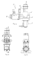
- a hydraulic device according to the invention shown in Figs. 1 to 6, employs an impeller to which at least one permanent magnet is mounted.
- the hydraulic device 1' is so provided that, in the presence of fluid flowing through it, a magnetic field is generated the value and/or variation of which depends on the fluid flow, in particular on the velocity and/or quantity and/or flow rate thereof.
- the hydraulic device 1' is adapted to be included in, for example, a water heating system like that shown in Figs. 15 and 16.
- Said flow meter may however be of any other known type.
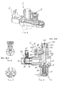
- the outlet duct 7" comprises internally a main duct 11" and a by-pass duct 9".
- the main duct 11" has an aperture 4"c, or through seat, an aperture 8" and an aperture 40"a which are opened or closed by respective on-off means; in particular, a tap or by-pass valve 3" allows or prevents water flow through the aperture 4"c, while a servo-assisted valve 2", preferably an electrically controlled one, allows or prevents water flow through the aperture 8" and a direct on-off solenoid valve 40", e.g. actuated by an electrothermal element, allows or prevents water flow through the aperture 40"a; the two on-off means 2" and 40" are arranged in series.
- the respective aperture is preferably small (otherwise too big and strong valve mechanisms and actuators would be needed) and therefore the quantity of water allowed to flow therethrough is small, especially if we consider the supply requirements of a hydraulic system like a household heating system.
- the fact that there is an additional servo-assisted valve 2" downstream of the direct-on-off valve 40" does not affect the above considerations about the dimensions of the aperture associated with the latter.
- the by-pass valve 3" is integrated with the main body 4" of the device 1" and comprises a mobile shutter 12" which can slide in a seat 4"c communicating with the duct 9" and can thus stop the fluid flow entering the duct 9";
- the seat 4"c is a through hole being transversal, in particular substantially orthogonal, to the axis A-A, and is used for housing at least partly the valve 3"; in particular, said hole leads into a chamber immediately upstream of the main duct 11".
- a second and a third sealing elements 15" and 16 e.g. a gasket or an O-ring; the element 15" provides additional sealing onto the duct 4"c, i.e. works in aid of the element 14"; the element 16" is adapted to prevent any leakage from the by-pass duct 9" to the outside of the device 1".
- the shutter 12" has a seat 17" for a suitable tool or wrench, such as a screwdriver, in order to allow the tap 3" to be operated, preferably by qualified personnel.
- a suitable tool or wrench such as a screwdriver
- the solenoid valve 2" is servo-assisted type and the opening and closing of said solenoid valve takes place through a shutter 10" which is moved by the magnetic field generated within a magnetic core due to electric current running through a coil.
- the magnetic field thus causes the movement of the shutter 10", on which a rubber piece 20" is mounted which opens and/or closes the aperture 8"; the opening of the passage 8", which is small, determines pressure variations in the chamber housing the core or shutter 10", which variations move a second mobile shutter, i.e. the one in which the passage 8" is obtained, which in turn opens a larger duct; this operation is typical of servo-assisted valves.
- the movement of the shutter 10" is counteracted by a spring being present inside the magnetic core.
- this second embodiment example like the first one, would be equally advantageous should the solenoid valve 2" be replaced with a different type of valve, such as a direct on-off valve.
- a non-return valve 50" is mounted on the outlet duct 7" of the hydraulic device 1".
- the non-return valve 50 which is known to the man skilled in the art, is of a type comprising at least one hollow cylindrical body 51" inserted in the duct 7" through a respective sealing element or O-ring 53".
- the valve 50" also comprises an inner shutter 52", e.g. having a substantially “mushroom-like” shape, i.e. comprising a stem which can slide in a central seat of said hollow cylindrical body 51" and an end cap adapted to close a suitable seat, thus stopping the water flow.
- an inner shutter 52 e.g. having a substantially “mushroom-like” shape, i.e. comprising a stem which can slide in a central seat of said hollow cylindrical body 51" and an end cap adapted to close a suitable seat, thus stopping the water flow.
- said non-return valve 50" may advantageously comprise some elements, e.g. the hollow cylindrical body 51", obtained directly from the body 4" of the device 1".
- This solution turns out to be advantageous for several reasons: on the one hand, it reduces the risks of leakage in the contact areas between the main body 4" of the hydraulic device 1" and the cylindrical body 51" of the non-return valve 50", while on the other hand the gasket 53" is no longer necessary (thus reducing the number of components used, and therefore the cost of the device).
- valve is controlled by an electrothermal shutter.
- thermoactuator 41 is "pull” type, i.e. when supplied with power it exerts a pulling action towards its own body, although its thermic element is “push” type; of course, the thermic element is suitably oriented for this purpose inside the element 41", in opposition to a reaction element or spring 40"d.
- thermoelectric element 41 The larger the aperture 40"a, the higher the force that must be exerted by the valve 40" in order to keep the aperture 40"a closed through said contrast spring 40"d adapted to push the shutter 40"b, and therefore the higher the forces to be overcome by the thermoelectric element 41".
- the aperture 40"a cannot be too large, otherwise it could not be closed by a standard valve 40", thus requiring bigger valves.
- thermoelectric valve which operates slowly
- valves of different types may improve safety, because they are subject to different potential causes of failure.
- the hydraulic device 1" may also advantageously comprise a sensor for detecting a significant parameter of the fluid flowing in the device, e.g. flow rate, temperature, hardness, pressure, etc.
- a pressure sensor 60" is housed in a seat 60"a located on the outlet duct 7" and is electrically connected, for example, to a system control unit (the wiring harness for the electronic connection between the sensor and the control unit and the control unit itself are not shown for simplicity's sake).
- the electric signal generated or caused by the pressure sensor 60" can be detected and/or utilized by a control unit, for example, in order to control topping up or filling operations automatically of the system.
- the hydraulic device 1" is also adapted to be included in a water heating system, as shown in Figs. 15 and 16.
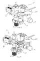
- the hydraulic device is designated as a whole by reference numeral 1"'.
- the hydraulic device 1"' bears many conceptual similarities to the device 1", though it features a number of advantageous implementation differences.
- the hydraulic device 1' comprises two on-off devices 2'" and 40'" arranged in series; however, in this example, they are two electromagnetically controlled solenoid valves (though they may alternatively be both electro thermally controlled valves or different types of valves) of the type being servo-assisted by fluid pressure.
- the main duct 11"' is subdivided into three sections 11"'a, 11"'b, 11"'c arranged in series.
- the valve 2"' through the servo-assisted movement of its shutter driven by the core 10"', allows to connect the section 11"'b to the downstream section 11"'c.
- the valve 40"' through the servo-assisted movement of its shutter driven by the core 10"", allows to connect the section 11"'a to the downstream section 11"'b.
- the inlet duct 6"' and the outlet duct 5"' are substantially aligned (in particular coaxial) and substantially the same size (a filter applied to the inlet duct 6'" may alternatively be incorporated in the duct itself).
- the duct 11"' extends in a substantially linear direction being transversal, in particular substantially orthogonal, to the axis of the duct 5"' and/or of the duct 6"', up to the duct 7"'.
- the body 4"' of the device 1"' there are two seats 4"'a and 4""a adapted to house at least partly the valves 2'" and 40"', respectively.
- the two valve seats are close side by side, and preferably have an axis which is transversal, in particular substantially orthogonal, to the duct 11"'.
- the tap seat has an axis being transversal, in particular substantially orthogonal, to the duct section 11"'c.
- the axes of the seats 4"'a, 4"'b and 4"'c are advantageously substantially parallel to one another; in particular, the tap seat is located on a side opposite to both valve seats.
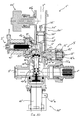
- the sensor 60' features very clever mechanical solutions; in fact, it utilizes a cylindrical body from which two ducts come out, in particular two small tubes preferably having a circular cross-section; one tube is associated with the element 61"', while the other is associated with the element 62"'.
- Said tubes are inserted in two adjacent holes or seats in the body 4"' of the hydraulic device 1"'.
- the tubes are in communication with the main duct 11'" and with the by-pass duct 9"'; in particular, one duct is in communication with the section 11"'c downstream of the shutter 10'" of the valve 2"" (i.e. with the outlet duct 7"', too), while the other duct is in communication with the duct 9"' immediately upstream of the seat 4"'c of the tap 3"'. Therefore, the two elements 61"' and 62"', which are preferably located in the body of the sensor 60'" in a position close to its outer surface, are able to carry out the above-mentioned pressure measurements.
- the elements 61"' and 62'" are associated with a support element which may typically be a printed circuit or an electronic circuit; electric connections are then associated with said circuit for carrying the signals of both detection elements out of the body of the sensor 60"'; in Fig. 12, said electric connections are represented by four electric leads, but one may also use a suitable electric connector or welded contacts, or else a different number or type of connections. Additional electric and/or electronic components may be associated with the support element, in particular with the printed circuit; thus, the signals of both elements 61"' and 62'" may, for example, be amplified and/or processed and/or stored (e.g. by a microcontroller or even a simpler circuitry); in such a case, the measurements carried out may also be sent, for example, to an electronic control unit through two electric leads only, e.g. by means of a serial connection.
- a support element which may typically be a printed circuit or an electronic circuit
- electric connections are then associated with said circuit for carrying the signals of both detection elements out of the
- the respective axes shall be substantially parallel. Also, for obtaining a proper arrangement of the sensor 60"', it is advantageous that these axes are transversal, in particular substantially orthogonal, to both the duct 9'" and the duct 11'"; more in particular, said axes shall also be substantially orthogonal both to the axes of the seats 4"'a and 4""a of the valves and to the seat 4"'c of the tap; thus, the sensor body will be positioned on one side of the body 4"' of the hydraulic device.
- the body of the pressure sensor may also be at least partly built in the body of the hydraulic device.
- the removable part may be the support (e.g. the printed circuit) of the measurement element(s) (at least during the assembly stage).
- At least one of the two devices is direct-control type, since this type can ensure the interruption of the flow between the inlet and the outlet even in the presence of anomalous pressures.
- a non-return valve may nonetheless be used as a safety measure should the solenoid valves fail.
- the hydraulic device according to the present invention comprises electric connection means for at least the on-off devices; said connection means are so connected that the operation or control of the on-off devices can take place either jointly or separately, in particular through same or respective electric signals.
- the hydraulic device according to the present invention may advantageously be used, for example, in a gas or electric boiler, typically for domestic use, in order to provide both the filling, in particular the manual filling, and the topping up, in particular the automatic topping up, of the same.
- Fig. 15 and Fig. 16 the hydraulic appliance is designated by numerals 100' and 100", respectively.
- the hydraulic device according to the present invention which is a single component, is designated by reference numeral 101, in particular 101' in the case of Fig. 15 and 101" in the case of Fig.16.
- the devices 101' and 101" are schematized as a solenoid valve and a tap connected together in parallel, and are located essentially in the same position as the flow meter 130.
- said solenoid valve may advantageously be replaced with two or more valves, e.g. arranged in series, as in the case of the devices 1" and 1"' according to the invention; also, said manual tap may be replaced with an automatic or controlled valve.
- the device 101 comprises an inlet duct 106, a first outlet duct 105 and a second outlet duct 107, and the flow meter 130 is associated with the first outlet duct 105.
- the components 101' and 101 in particular their inlet ducts 106' and 106", are respectively connected to the main inlet of the appliance; said inlet is typically connected to the water supply network of the hydraulic system of the house or building, i.e. connected to the water meter through suitable plumbing.
- household hydraulic systems which generally comprise at least one hydraulic circuit for heating water and at least one hydraulic circuit for sanitary water.
- the heating circuit is substantially a "closed circuit", i.e. a liquid circulates continuously between a boiler and suitable radiators adapted to heat the environment; the liquid is generally water, with the possible addition of additives, e.g. antifreeze, etc.
- the sanitary circuit is substantially an "open circuit", in which water (from the public main) flows in, is heated and then flows out through the taps of the house (generally for alimentary or hygienic use); usually a drain is available at each tap for draining the water (e.g. into the public drainage system).
- the two circuits i.e. the heating and the sanitary circuits
- the two circuits are substantially independent of each other.
- the first outlet 105' is connected to the inlet 106' through a duct which is preferably always open; near the outlet 105', there is preferably at least one sensor 130', such as a flow meter; said sensor may however be mounted or connected hydraulically in another location or to another part of the appliance or of the system.
- the second outlet 107' is connected to the inlet 106' through two fluid flow on-off means connected in parallel, in particular a tap 103' and at least one solenoid valve 102'; preferably at least one non-return valve 150' is associated with the outlet 107'.
- the device 101' has been described in a very concise manner because detailed descriptions of devices according to the present invention have already been provided above. However, it should be taken into account that the appliance 100' may use different hydraulic devices according to the teachings of the present invention; for example, the hydraulic device employed may be fitted with two solenoid valves in series instead of the single solenoid valve 102' shown in Fig. 15.
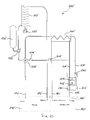
- the appliance of Fig. 15 comprises one section dedicated to the treatment of sanitary water and one section dedicated to the treatment of heating water.
- the heating water section comprises the respective inlet 191', the respective outlet 192', a fuel burner 171', such as a gas burner, a primary heat exchanger 172', a circulator 175', an expansion tank 176', and a number of connection pipes.
- the heating water enters the appliance through the inlet 191' (called "return"), flows through the circulator 175', flows through the exchanger 172' (which warms up the water by using the heat received from the burner 171'), and exits the appliance through the outlet 192' (called “delivery").
- the section for sanitary water comprises the respective inlet 181' (called “main inlet”), the respective outlet 182', and a secondary exchanger 200'.
- cold sanitary water enters the appliance through the inlet 181' and flows through the exchanger 200', after which hot water exits the appliance through the outlet 182'.
- the diverting solenoid valve 205' is connected to four pipes. With reference to Fig. 15, the pipe at the top is connected directly to the secondary exchanger 200', the pipe at the bottom is connected to the inlet 191' or heating return of the appliance, the pipe on the left is connected to the circulator 175', the pipe on the right is connected to the exchanger 172'; in said hydraulic connections there are also unidirectional valves 206' and 207'.
- the heating water circulates not only in the primary exchanger 172' (associated with the burner 171'), but also in the secondary exchanger 200'; thus the heating water is also used for heating the sanitary water, thanks to the secondary exchanger.
- the heating water In a second operating condition, the heating water only circulates in the primary exchanger 172', not in the secondary exchanger 200'; thus the heating water is only used for the heating system.
- the filling or topping-up operation is preferably carried out when the solenoid valve 205' is in the first operating condition, i.e. when the device 101' is in hydraulic communication with the whole system.
- the filling or topping-up operation may also be carried out in different phases or conditions.
- the appliance 100" of Fig. 16 differs from the appliance 100' of Fig. 15 in the way in which the hydraulic device according to the present invention has been included in said appliance.
- the component 101" is connected to the sanitary water section as follows: the inlet 106" is connected to the inlet 181" of the appliance, the outlet 105" is connected to an inlet of the exchanger 200" of the appliance.
- the component 101" is also connected to the heating water section as follows: the outlet 107" is connected through a T-shaped fitting to an inlet of the exchanger 200" and (indirectly) to the solenoid valve 205".
- the appliance according to the present invention may advantageously comprise an electronic control unit to control the operation of the hydraulic appliance.
Landscapes
- Engineering & Computer Science (AREA)
- Physics & Mathematics (AREA)
- Thermal Sciences (AREA)
- Chemical & Material Sciences (AREA)
- Combustion & Propulsion (AREA)
- Mechanical Engineering (AREA)
- General Engineering & Computer Science (AREA)
- Fluid-Pressure Circuits (AREA)
- Valve Device For Special Equipments (AREA)
Priority Applications (1)
| Application Number | Priority Date | Filing Date | Title |
|---|---|---|---|
| PL07103489T PL1832816T3 (pl) | 2006-03-09 | 2007-03-05 | Urządzenie hydrauliczne, narzędzie hydrauliczne i układ hydrauliczny oraz sposób jego zastosowania |
Applications Claiming Priority (1)
| Application Number | Priority Date | Filing Date | Title |
|---|---|---|---|
| IT000177A ITTO20060177A1 (it) | 2006-03-09 | 2006-03-09 | Dispositivo idraulico, apparecchiatura idraulica, impianto idraulico e metodo per il suo utilizzo |
Publications (3)
| Publication Number | Publication Date |
|---|---|
| EP1832816A2 true EP1832816A2 (fr) | 2007-09-12 |
| EP1832816A3 EP1832816A3 (fr) | 2013-04-03 |
| EP1832816B1 EP1832816B1 (fr) | 2016-12-28 |
Family
ID=38117053
Family Applications (1)
| Application Number | Title | Priority Date | Filing Date |
|---|---|---|---|
| EP07103489.6A Active EP1832816B1 (fr) | 2006-03-09 | 2007-03-05 | Dispositif hydraulique, appareil hydraulique, système hydraulique et son procédé d'utilisation |
Country Status (6)
| Country | Link |
|---|---|
| EP (1) | EP1832816B1 (fr) |
| DK (1) | DK1832816T3 (fr) |
| ES (1) | ES2619158T3 (fr) |
| IT (1) | ITTO20060177A1 (fr) |
| PL (1) | PL1832816T3 (fr) |
| PT (1) | PT1832816T (fr) |
Cited By (10)
| Publication number | Priority date | Publication date | Assignee | Title |
|---|---|---|---|---|
| US20100263754A1 (en) * | 2007-09-26 | 2010-10-21 | Bradford White Corporation | Water heater having temperature control system with thermostatically controlled mixing device |
| EP2101123B1 (fr) | 2008-03-11 | 2016-11-02 | ELBI International S.p.A. | Unité de sectionneur d'eau, en particulier pour contrôler l'alimentation en eau dans un circuit d'eau d'une chaudière |
| CN106979612A (zh) * | 2017-04-28 | 2017-07-25 | 广东万和热能科技有限公司 | 壁挂炉 |
| WO2017212226A1 (fr) * | 2016-06-10 | 2017-12-14 | Bernard Cook | Appareil de remplissage automatique de système de chauffage, procédé d'amélioration de la sécurité d'un système de chauffage, procédé de test automatique et procédé de gestion d'un système de chauffage à réapprovisionnement automatique |
| EP3260795A1 (fr) * | 2016-06-20 | 2017-12-27 | Bosch Termoteknik Isitma ve Kilma San. Tic. A.S. | Dispositif d'appareil de chauffage |
| EP3222929A4 (fr) * | 2014-11-19 | 2018-08-08 | Kyungdong Navien Co., Ltd. | Chaudière ayant un clapet de retenue intégré à une conduite d'eau |
| NL2019988B1 (nl) * | 2017-11-28 | 2019-06-05 | Remeha B V | Samenstel voor het op een werkdruk brengen en/of houden van een CV-leidingstelsel, een CV-ketel en een CV-installatie |
| EP3671048A1 (fr) * | 2018-12-21 | 2020-06-24 | Robert Bosch GmbH | Dispositif d'installation de combustion et/ou de chauffage |
| EP3693671A1 (fr) * | 2019-02-08 | 2020-08-12 | Vaillant GmbH | Système de remplissage doté d'un dispositif d'actionnement thermique |
| EP3919793A1 (fr) * | 2020-06-05 | 2021-12-08 | Pietro Fiorentini S.P.A. | Procédé de commande d'une soupape |
Families Citing this family (2)
| Publication number | Priority date | Publication date | Assignee | Title |
|---|---|---|---|---|
| GB2628110A (en) * | 2023-03-13 | 2024-09-18 | Stuart Turner Ltd | Pressure fill device |
| GB2628111A (en) * | 2023-03-13 | 2024-09-18 | Stuart Turner Ltd | Pressure fill device |
Family Cites Families (3)
| Publication number | Priority date | Publication date | Assignee | Title |
|---|---|---|---|---|
| DE8219381U1 (de) * | 1982-07-07 | 1982-08-26 | August Beul, Armaturenfabrik und Metallgießerei, 5952 Attendorn | Ventilblock fuer den anschluss von zusatzgeraeten zur aufbereitung des wassers einer hausversorgungsleitung |
| DE19511369A1 (de) * | 1994-03-28 | 1995-10-05 | Vaillant Joh Gmbh & Co | Wasserheizanlage zur Bereitung von Brauch- und Heizwasser |
| US6021805A (en) * | 1998-06-09 | 2000-02-08 | Watts Investment Company | Backflow preventer assembly |
-
2006
- 2006-03-09 IT IT000177A patent/ITTO20060177A1/it unknown
-
2007
- 2007-03-05 ES ES07103489.6T patent/ES2619158T3/es active Active
- 2007-03-05 PL PL07103489T patent/PL1832816T3/pl unknown
- 2007-03-05 PT PT71034896T patent/PT1832816T/pt unknown
- 2007-03-05 DK DK07103489.6T patent/DK1832816T3/en active
- 2007-03-05 EP EP07103489.6A patent/EP1832816B1/fr active Active
Cited By (13)
| Publication number | Priority date | Publication date | Assignee | Title |
|---|---|---|---|---|
| US20100263754A1 (en) * | 2007-09-26 | 2010-10-21 | Bradford White Corporation | Water heater having temperature control system with thermostatically controlled mixing device |
| EP2101123B1 (fr) | 2008-03-11 | 2016-11-02 | ELBI International S.p.A. | Unité de sectionneur d'eau, en particulier pour contrôler l'alimentation en eau dans un circuit d'eau d'une chaudière |
| EP2101123B2 (fr) † | 2008-03-11 | 2020-08-05 | ELBI International S.p.A. | Unité de sectionneur d'eau, en particulier pour contrôler l'alimentation en eau dans un circuit d'eau d'une chaudière |
| EP3222929A4 (fr) * | 2014-11-19 | 2018-08-08 | Kyungdong Navien Co., Ltd. | Chaudière ayant un clapet de retenue intégré à une conduite d'eau |
| WO2017212226A1 (fr) * | 2016-06-10 | 2017-12-14 | Bernard Cook | Appareil de remplissage automatique de système de chauffage, procédé d'amélioration de la sécurité d'un système de chauffage, procédé de test automatique et procédé de gestion d'un système de chauffage à réapprovisionnement automatique |
| GB2551192B (en) * | 2016-06-10 | 2019-10-16 | Cook Bernard | Automatic heating-system filling apparatus |
| EP3260795A1 (fr) * | 2016-06-20 | 2017-12-27 | Bosch Termoteknik Isitma ve Kilma San. Tic. A.S. | Dispositif d'appareil de chauffage |
| CN106979612A (zh) * | 2017-04-28 | 2017-07-25 | 广东万和热能科技有限公司 | 壁挂炉 |
| CN106979612B (zh) * | 2017-04-28 | 2022-12-20 | 广东万和热能科技有限公司 | 壁挂炉 |
| NL2019988B1 (nl) * | 2017-11-28 | 2019-06-05 | Remeha B V | Samenstel voor het op een werkdruk brengen en/of houden van een CV-leidingstelsel, een CV-ketel en een CV-installatie |
| EP3671048A1 (fr) * | 2018-12-21 | 2020-06-24 | Robert Bosch GmbH | Dispositif d'installation de combustion et/ou de chauffage |
| EP3693671A1 (fr) * | 2019-02-08 | 2020-08-12 | Vaillant GmbH | Système de remplissage doté d'un dispositif d'actionnement thermique |
| EP3919793A1 (fr) * | 2020-06-05 | 2021-12-08 | Pietro Fiorentini S.P.A. | Procédé de commande d'une soupape |
Also Published As
| Publication number | Publication date |
|---|---|
| DK1832816T3 (en) | 2017-03-27 |
| EP1832816A3 (fr) | 2013-04-03 |
| PL1832816T3 (pl) | 2017-07-31 |
| ITTO20060177A1 (it) | 2007-09-10 |
| EP1832816B1 (fr) | 2016-12-28 |
| PT1832816T (pt) | 2017-03-15 |
| ES2619158T3 (es) | 2017-06-23 |
Similar Documents
| Publication | Publication Date | Title |
|---|---|---|
| EP1832816B1 (fr) | Dispositif hydraulique, appareil hydraulique, système hydraulique et son procédé d'utilisation | |
| US7073528B2 (en) | Water pump and thermostatically controlled bypass valve | |
| US7740182B2 (en) | Method and system for controlled release of hot water from a fixture | |
| US7970494B2 (en) | Systems and methods for monitoring relief valve drain in hot water Heater | |
| EP2554919B1 (fr) | Dispositif modulaire pour économiser l'eau | |
| CA2539958C (fr) | Soupape de sectionnement munie d'une soupape en drain | |
| US8231064B2 (en) | Water control fixture having auxiliary functions | |
| US20100212752A1 (en) | Shut Off Protection For Hot Water Heater | |
| WO2006014891A1 (fr) | Systèmes et procédés pour détecter et éliminer les fuites dans les systèmes de distribution d'eau à utiliser avec les appareils | |
| EP2422021A1 (fr) | Système d'approvisionnement en eau à recirculation | |
| JP2010501824A (ja) | 飲料作成器の流れ検出ロジック | |
| EP0568122A2 (fr) | Arrangement de soupape prévu pour installations de chauffage ainsi que pour chauffe-eau domestique | |
| US20070089790A1 (en) | Assembly for connecting a water supply to heating systems with a water heater | |
| RU2763810C1 (ru) | Проточный водонагреватель и способ предотвращения его повреждения | |
| EP1831609B1 (fr) | Echangeur thermique pour chaudiere combinee, et chaudiere combinee utilisant un tel echangeur thermique | |
| WO2008123785A1 (fr) | Ameliorations apportees a des systemes de fluide | |
| KR20120023251A (ko) | 형상기억합금으로 구동되는 개폐밸브를 포함하는 온수 보일러 절수시스템 | |
| EP3653941B1 (fr) | Système de recirculation de fluide | |
| JP3744340B2 (ja) | 自動補水ユニット及びこの自動補水ユニットを用いた補水制御方法 | |
| KR101609094B1 (ko) | 온수 순환배관장치 | |
| CN214172530U (zh) | 一种防混水的即热式热水器 | |
| EP3693671B1 (fr) | Système de remplissage doté d'un dispositif d'actionnement thermique | |
| EP0240390B1 (fr) | Dispositif de sécurité pour chaudière à gaz du type à ventilation mécanique controlée | |
| JP2005061640A (ja) | ソーラ給湯装置付き湯制御装置およびソーラ給湯装置付加方法 | |
| JP4318308B2 (ja) | 給湯装置 |
Legal Events
| Date | Code | Title | Description |
|---|---|---|---|
| PUAI | Public reference made under article 153(3) epc to a published international application that has entered the european phase |
Free format text: ORIGINAL CODE: 0009012 |
|
| AK | Designated contracting states |
Kind code of ref document: A2 Designated state(s): AT BE BG CH CY CZ DE DK EE ES FI FR GB GR HU IE IS IT LI LT LU LV MC MT NL PL PT RO SE SI SK TR |
|
| AX | Request for extension of the european patent |
Extension state: AL BA HR MK YU |
|
| PUAL | Search report despatched |
Free format text: ORIGINAL CODE: 0009013 |
|
| AK | Designated contracting states |
Kind code of ref document: A3 Designated state(s): AT BE BG CH CY CZ DE DK EE ES FI FR GB GR HU IE IS IT LI LT LU LV MC MT NL PL PT RO SE SI SK TR |
|
| AX | Request for extension of the european patent |
Extension state: AL BA HR MK RS |
|
| RIC1 | Information provided on ipc code assigned before grant |
Ipc: F24H 9/12 20060101ALI20130226BHEP Ipc: F24D 3/10 20060101AFI20130226BHEP |
|
| 17P | Request for examination filed |
Effective date: 20131001 |
|
| RBV | Designated contracting states (corrected) |
Designated state(s): AT BE BG CH CY CZ DE DK EE ES FI FR GB GR HU IE IS IT LI LT LU LV MC MT NL PL PT RO SE SI SK TR |
|
| AKX | Designation fees paid |
Designated state(s): AT BE BG CH CY CZ DE DK EE ES FI FR GB GR HU IE IS IT LI LT LU LV MC MT NL PL PT RO SE SI SK TR |
|
| 17Q | First examination report despatched |
Effective date: 20150508 |
|
| GRAP | Despatch of communication of intention to grant a patent |
Free format text: ORIGINAL CODE: EPIDOSNIGR1 |
|
| INTG | Intention to grant announced |
Effective date: 20160901 |
|
| GRAS | Grant fee paid |
Free format text: ORIGINAL CODE: EPIDOSNIGR3 |
|
| GRAA | (expected) grant |
Free format text: ORIGINAL CODE: 0009210 |
|
| AK | Designated contracting states |
Kind code of ref document: B1 Designated state(s): AT BE BG CH CY CZ DE DK EE ES FI FR GB GR HU IE IS IT LI LT LU LV MC MT NL PL PT RO SE SI SK TR |
|
| REG | Reference to a national code |
Ref country code: GB Ref legal event code: FG4D |
|
| REG | Reference to a national code |
Ref country code: CH Ref legal event code: EP |
|
| REG | Reference to a national code |
Ref country code: AT Ref legal event code: REF Ref document number: 857640 Country of ref document: AT Kind code of ref document: T Effective date: 20170115 |
|
| REG | Reference to a national code |
Ref country code: IE Ref legal event code: FG4D |
|
| REG | Reference to a national code |
Ref country code: DE Ref legal event code: R096 Ref document number: 602007049294 Country of ref document: DE |
|
| PG25 | Lapsed in a contracting state [announced via postgrant information from national office to epo] |
Ref country code: LV Free format text: LAPSE BECAUSE OF FAILURE TO SUBMIT A TRANSLATION OF THE DESCRIPTION OR TO PAY THE FEE WITHIN THE PRESCRIBED TIME-LIMIT Effective date: 20161228 |
|
| REG | Reference to a national code |
Ref country code: PT Ref legal event code: SC4A Ref document number: 1832816 Country of ref document: PT Date of ref document: 20170315 Kind code of ref document: T Free format text: AVAILABILITY OF NATIONAL TRANSLATION Effective date: 20170309 |
|
| REG | Reference to a national code |
Ref country code: FR Ref legal event code: PLFP Year of fee payment: 11 |
|
| REG | Reference to a national code |
Ref country code: DK Ref legal event code: T3 Effective date: 20170321 |
|
| REG | Reference to a national code |
Ref country code: NL Ref legal event code: FP |
|
| REG | Reference to a national code |
Ref country code: LT Ref legal event code: MG4D |
|
| PG25 | Lapsed in a contracting state [announced via postgrant information from national office to epo] |
Ref country code: SE Free format text: LAPSE BECAUSE OF FAILURE TO SUBMIT A TRANSLATION OF THE DESCRIPTION OR TO PAY THE FEE WITHIN THE PRESCRIBED TIME-LIMIT Effective date: 20161228 Ref country code: GR Free format text: LAPSE BECAUSE OF FAILURE TO SUBMIT A TRANSLATION OF THE DESCRIPTION OR TO PAY THE FEE WITHIN THE PRESCRIBED TIME-LIMIT Effective date: 20170329 Ref country code: LT Free format text: LAPSE BECAUSE OF FAILURE TO SUBMIT A TRANSLATION OF THE DESCRIPTION OR TO PAY THE FEE WITHIN THE PRESCRIBED TIME-LIMIT Effective date: 20161228 |
|
| REG | Reference to a national code |
Ref country code: AT Ref legal event code: MK05 Ref document number: 857640 Country of ref document: AT Kind code of ref document: T Effective date: 20161228 |
|
| PG25 | Lapsed in a contracting state [announced via postgrant information from national office to epo] |
Ref country code: FI Free format text: LAPSE BECAUSE OF FAILURE TO SUBMIT A TRANSLATION OF THE DESCRIPTION OR TO PAY THE FEE WITHIN THE PRESCRIBED TIME-LIMIT Effective date: 20161228 |
|
| REG | Reference to a national code |
Ref country code: ES Ref legal event code: FG2A Ref document number: 2619158 Country of ref document: ES Kind code of ref document: T3 Effective date: 20170623 |
|
| PG25 | Lapsed in a contracting state [announced via postgrant information from national office to epo] |
Ref country code: RO Free format text: LAPSE BECAUSE OF FAILURE TO SUBMIT A TRANSLATION OF THE DESCRIPTION OR TO PAY THE FEE WITHIN THE PRESCRIBED TIME-LIMIT Effective date: 20161228 Ref country code: EE Free format text: LAPSE BECAUSE OF FAILURE TO SUBMIT A TRANSLATION OF THE DESCRIPTION OR TO PAY THE FEE WITHIN THE PRESCRIBED TIME-LIMIT Effective date: 20161228 Ref country code: CZ Free format text: LAPSE BECAUSE OF FAILURE TO SUBMIT A TRANSLATION OF THE DESCRIPTION OR TO PAY THE FEE WITHIN THE PRESCRIBED TIME-LIMIT Effective date: 20161228 Ref country code: IS Free format text: LAPSE BECAUSE OF FAILURE TO SUBMIT A TRANSLATION OF THE DESCRIPTION OR TO PAY THE FEE WITHIN THE PRESCRIBED TIME-LIMIT Effective date: 20170428 |
|
| PG25 | Lapsed in a contracting state [announced via postgrant information from national office to epo] |
Ref country code: BE Free format text: LAPSE BECAUSE OF FAILURE TO SUBMIT A TRANSLATION OF THE DESCRIPTION OR TO PAY THE FEE WITHIN THE PRESCRIBED TIME-LIMIT Effective date: 20161228 Ref country code: BG Free format text: LAPSE BECAUSE OF FAILURE TO SUBMIT A TRANSLATION OF THE DESCRIPTION OR TO PAY THE FEE WITHIN THE PRESCRIBED TIME-LIMIT Effective date: 20170328 Ref country code: AT Free format text: LAPSE BECAUSE OF FAILURE TO SUBMIT A TRANSLATION OF THE DESCRIPTION OR TO PAY THE FEE WITHIN THE PRESCRIBED TIME-LIMIT Effective date: 20161228 |
|
| REG | Reference to a national code |
Ref country code: SK Ref legal event code: T3 Ref document number: E 23775 Country of ref document: SK |
|
| REG | Reference to a national code |
Ref country code: DE Ref legal event code: R097 Ref document number: 602007049294 Country of ref document: DE |
|
| REG | Reference to a national code |
Ref country code: CH Ref legal event code: PL |
|
| PLBE | No opposition filed within time limit |
Free format text: ORIGINAL CODE: 0009261 |
|
| STAA | Information on the status of an ep patent application or granted ep patent |
Free format text: STATUS: NO OPPOSITION FILED WITHIN TIME LIMIT |
|
| PG25 | Lapsed in a contracting state [announced via postgrant information from national office to epo] |
Ref country code: MC Free format text: LAPSE BECAUSE OF FAILURE TO SUBMIT A TRANSLATION OF THE DESCRIPTION OR TO PAY THE FEE WITHIN THE PRESCRIBED TIME-LIMIT Effective date: 20161228 |
|
| 26N | No opposition filed |
Effective date: 20170929 |
|
| REG | Reference to a national code |
Ref country code: IE Ref legal event code: MM4A |
|
| PG25 | Lapsed in a contracting state [announced via postgrant information from national office to epo] |
Ref country code: LU Free format text: LAPSE BECAUSE OF NON-PAYMENT OF DUE FEES Effective date: 20170305 |
|
| PG25 | Lapsed in a contracting state [announced via postgrant information from national office to epo] |
Ref country code: SI Free format text: LAPSE BECAUSE OF FAILURE TO SUBMIT A TRANSLATION OF THE DESCRIPTION OR TO PAY THE FEE WITHIN THE PRESCRIBED TIME-LIMIT Effective date: 20161228 Ref country code: IE Free format text: LAPSE BECAUSE OF NON-PAYMENT OF DUE FEES Effective date: 20170305 Ref country code: CH Free format text: LAPSE BECAUSE OF NON-PAYMENT OF DUE FEES Effective date: 20170331 Ref country code: LI Free format text: LAPSE BECAUSE OF NON-PAYMENT OF DUE FEES Effective date: 20170331 |
|
| REG | Reference to a national code |
Ref country code: FR Ref legal event code: PLFP Year of fee payment: 12 |
|
| PG25 | Lapsed in a contracting state [announced via postgrant information from national office to epo] |
Ref country code: MT Free format text: LAPSE BECAUSE OF NON-PAYMENT OF DUE FEES Effective date: 20170305 |
|
| PGFP | Annual fee paid to national office [announced via postgrant information from national office to epo] |
Ref country code: PL Payment date: 20190222 Year of fee payment: 13 |
|
| PG25 | Lapsed in a contracting state [announced via postgrant information from national office to epo] |
Ref country code: HU Free format text: LAPSE BECAUSE OF FAILURE TO SUBMIT A TRANSLATION OF THE DESCRIPTION OR TO PAY THE FEE WITHIN THE PRESCRIBED TIME-LIMIT; INVALID AB INITIO Effective date: 20070305 |
|
| PGFP | Annual fee paid to national office [announced via postgrant information from national office to epo] |
Ref country code: SK Payment date: 20190227 Year of fee payment: 13 |
|
| PGFP | Annual fee paid to national office [announced via postgrant information from national office to epo] |
Ref country code: AT Payment date: 20181220 Year of fee payment: 14 |
|
| PG25 | Lapsed in a contracting state [announced via postgrant information from national office to epo] |
Ref country code: CY Free format text: LAPSE BECAUSE OF NON-PAYMENT OF DUE FEES Effective date: 20161228 |
|
| PGFP | Annual fee paid to national office [announced via postgrant information from national office to epo] |
Ref country code: IT Payment date: 20200331 Year of fee payment: 14 Ref country code: DK Payment date: 20200320 Year of fee payment: 14 Ref country code: GB Payment date: 20200324 Year of fee payment: 14 Ref country code: NL Payment date: 20200325 Year of fee payment: 14 |
|
| PGFP | Annual fee paid to national office [announced via postgrant information from national office to epo] |
Ref country code: TR Payment date: 20200305 Year of fee payment: 14 |
|
| PGFP | Annual fee paid to national office [announced via postgrant information from national office to epo] |
Ref country code: FR Payment date: 20200401 Year of fee payment: 14 Ref country code: DE Payment date: 20200402 Year of fee payment: 14 |
|
| REG | Reference to a national code |
Ref country code: SK Ref legal event code: MM4A Ref document number: E 23775 Country of ref document: SK Effective date: 20200305 |
|
| PG25 | Lapsed in a contracting state [announced via postgrant information from national office to epo] |
Ref country code: PT Free format text: LAPSE BECAUSE OF NON-PAYMENT OF DUE FEES Effective date: 20201009 |
|
| PG25 | Lapsed in a contracting state [announced via postgrant information from national office to epo] |
Ref country code: SK Free format text: LAPSE BECAUSE OF NON-PAYMENT OF DUE FEES Effective date: 20200305 |
|
| REG | Reference to a national code |
Ref country code: ES Ref legal event code: FD2A Effective date: 20210727 |
|
| REG | Reference to a national code |
Ref country code: DE Ref legal event code: R119 Ref document number: 602007049294 Country of ref document: DE |
|
| REG | Reference to a national code |
Ref country code: DK Ref legal event code: EBP Effective date: 20210331 |
|
| REG | Reference to a national code |
Ref country code: NL Ref legal event code: MM Effective date: 20210401 |
|
| GBPC | Gb: european patent ceased through non-payment of renewal fee |
Effective date: 20210305 |
|
| PG25 | Lapsed in a contracting state [announced via postgrant information from national office to epo] |
Ref country code: ES Free format text: LAPSE BECAUSE OF NON-PAYMENT OF DUE FEES Effective date: 20200306 |
|
| PG25 | Lapsed in a contracting state [announced via postgrant information from national office to epo] |
Ref country code: NL Free format text: LAPSE BECAUSE OF NON-PAYMENT OF DUE FEES Effective date: 20210401 Ref country code: FR Free format text: LAPSE BECAUSE OF NON-PAYMENT OF DUE FEES Effective date: 20210331 Ref country code: GB Free format text: LAPSE BECAUSE OF NON-PAYMENT OF DUE FEES Effective date: 20210305 Ref country code: DE Free format text: LAPSE BECAUSE OF NON-PAYMENT OF DUE FEES Effective date: 20211001 |
|
| PG25 | Lapsed in a contracting state [announced via postgrant information from national office to epo] |
Ref country code: IT Free format text: LAPSE BECAUSE OF NON-PAYMENT OF DUE FEES Effective date: 20210305 Ref country code: DK Free format text: LAPSE BECAUSE OF NON-PAYMENT OF DUE FEES Effective date: 20210331 |
|
| PG25 | Lapsed in a contracting state [announced via postgrant information from national office to epo] |
Ref country code: PL Free format text: LAPSE BECAUSE OF NON-PAYMENT OF DUE FEES Effective date: 20200305 |