EP3671048A1 - Dispositif d'installation de combustion et/ou de chauffage - Google Patents
Dispositif d'installation de combustion et/ou de chauffage Download PDFInfo
- Publication number
- EP3671048A1 EP3671048A1 EP19208267.5A EP19208267A EP3671048A1 EP 3671048 A1 EP3671048 A1 EP 3671048A1 EP 19208267 A EP19208267 A EP 19208267A EP 3671048 A1 EP3671048 A1 EP 3671048A1
- Authority
- EP
- European Patent Office
- Prior art keywords
- fluid
- output
- control
- unit
- output unit
- Prior art date
- Legal status (The legal status is an assumption and is not a legal conclusion. Google has not performed a legal analysis and makes no representation as to the accuracy of the status listed.)
- Withdrawn
Links
- 238000010438 heat treatment Methods 0.000 title claims abstract description 69
- 239000000446 fuel Substances 0.000 title 1
- 239000012530 fluid Substances 0.000 claims abstract description 318
- 230000001105 regulatory effect Effects 0.000 claims abstract description 85
- 238000002485 combustion reaction Methods 0.000 claims abstract description 60
- 239000008236 heating water Substances 0.000 claims abstract description 7
- 230000003287 optical effect Effects 0.000 claims description 43
- 230000004913 activation Effects 0.000 claims description 31
- 238000000034 method Methods 0.000 claims description 17
- 238000001514 detection method Methods 0.000 abstract 1
- 230000006870 function Effects 0.000 description 60
- 238000001994 activation Methods 0.000 description 29
- 230000009849 deactivation Effects 0.000 description 6
- XLYOFNOQVPJJNP-UHFFFAOYSA-N water Substances O XLYOFNOQVPJJNP-UHFFFAOYSA-N 0.000 description 4
- 230000003213 activating effect Effects 0.000 description 2
- 230000005540 biological transmission Effects 0.000 description 2
- 239000003086 colorant Substances 0.000 description 2
- 238000004891 communication Methods 0.000 description 2
- 230000001276 controlling effect Effects 0.000 description 2
- 239000002826 coolant Substances 0.000 description 2
- 238000005516 engineering process Methods 0.000 description 2
- 238000011156 evaluation Methods 0.000 description 2
- 230000001939 inductive effect Effects 0.000 description 2
- 230000008054 signal transmission Effects 0.000 description 2
- 230000001419 dependent effect Effects 0.000 description 1
- 238000010304 firing Methods 0.000 description 1
- 238000009434 installation Methods 0.000 description 1
Images

Classifications
-
- F—MECHANICAL ENGINEERING; LIGHTING; HEATING; WEAPONS; BLASTING
- F24—HEATING; RANGES; VENTILATING
- F24D—DOMESTIC- OR SPACE-HEATING SYSTEMS, e.g. CENTRAL HEATING SYSTEMS; DOMESTIC HOT-WATER SUPPLY SYSTEMS; ELEMENTS OR COMPONENTS THEREFOR
- F24D3/00—Hot-water central heating systems
- F24D3/10—Feed-line arrangements, e.g. providing for heat-accumulator tanks, expansion tanks ; Hydraulic components of a central heating system
- F24D3/1083—Filling valves or arrangements for filling
-
- F—MECHANICAL ENGINEERING; LIGHTING; HEATING; WEAPONS; BLASTING
- F24—HEATING; RANGES; VENTILATING
- F24D—DOMESTIC- OR SPACE-HEATING SYSTEMS, e.g. CENTRAL HEATING SYSTEMS; DOMESTIC HOT-WATER SUPPLY SYSTEMS; ELEMENTS OR COMPONENTS THEREFOR
- F24D19/00—Details
- F24D19/10—Arrangement or mounting of control or safety devices
- F24D19/1006—Arrangement or mounting of control or safety devices for water heating systems
- F24D19/1009—Arrangement or mounting of control or safety devices for water heating systems for central heating
- F24D19/1015—Arrangement or mounting of control or safety devices for water heating systems for central heating using a valve or valves
- F24D19/1036—Having differential pressure measurement facilities
-
- F—MECHANICAL ENGINEERING; LIGHTING; HEATING; WEAPONS; BLASTING
- F24—HEATING; RANGES; VENTILATING
- F24D—DOMESTIC- OR SPACE-HEATING SYSTEMS, e.g. CENTRAL HEATING SYSTEMS; DOMESTIC HOT-WATER SUPPLY SYSTEMS; ELEMENTS OR COMPONENTS THEREFOR
- F24D2220/00—Components of central heating installations excluding heat sources
- F24D2220/04—Sensors
- F24D2220/046—Pressure sensors
Definitions
- combustion and / or heating system device with at least one fluid circuit, in particular a heating water circuit, which has at least one fluid line provided for fluid guidance of a fluid, with at least one, in particular digital, pressure sensor for detecting a fluid pressure in the fluid line and with at least one a control and / or regulating unit has been proposed.
- the invention is based on a combustion and / or heating system device with at least one fluid circuit, in particular a heating water circuit, which has at least one fluid line provided for fluid guidance of a fluid, with at least one, in particular digital, pressure sensor for detecting a fluid pressure in the fluid line and with at least one control and / or regulating unit.
- the combustion and / or heating system device comprise at least one output unit, the control and / or regulating unit being set up to output the output unit, particularly during a filling of the fluid line, as a function of a fluid pressure detected by means of the pressure sensor a signal output to control.
- the firing and / or heating system device is preferably used as a condensing boiler, as a heating boiler or as another device that appears useful to a person skilled in the art Burning and / or heating system device formed.
- the combustion and / or heating system device preferably comprises further fluid and / or heating-relevant components, such as, for example, a heat cell, a heat exchanger, a boiler, a buffer store, a solar collector, a valve, in particular a three-way valve, a pump, a radiator or the like
- the fluid and / or heating-relevant components at least partially form the fluid circuit.
- the fluid and / or heating-relevant components are fluidly connected to one another by the at least one fluid line.
- “Provided” is to be understood in particular to be specially equipped and / or specially equipped.
- “Set up” is to be understood in particular to be specially programmed and / or specially designed. The fact that an object is provided or set up for a specific function should in particular be understood to mean that the object fulfills and / or executes this specific function in at least one application and / or operating state.
- the fluid line is preferably provided for fluid guidance of a fluid designed as water, in particular as heating water.
- the fluid line is provided for a fluid guidance of a fluid designed as a coolant, an air, in particular heating air, or the like.
- the fluid line can preferably be filled with a fluid from a supply network, in particular from a supply network present at an installation site of the combustion and / or heating system device, such as, for example, a local water supply network.
- the combustion and / or heating system device and / or the supply network has / have at least one filling tap for filling, in particular controlled, the fluid line with a fluid.
- the fluid line is designed as a tube, as a hose or as another fluid line which appears to be useful to a person skilled in the art.
- a fluid flowing through the fluid line preferably generates a fluid pressure in the fluid line.
- the pressure sensor is preferably set up to measure the fluid pressure in the fluid line.
- the pressure sensor is preferably designed as a digital pressure sensor, in particular set up as a function of a detected fluid pressure for outputting digitally processable measured values.
- the pressure sensor is set up to output the measured values in the form of electrical parameters, such as an electrical voltage or an electrical current.
- the pressure sensor is preferably different formed by an analog, in particular mechanical, pressure sensor.
- the pressure sensor is designed differently from a, in particular analog, manometer.
- the combustion and / or heating system device can preferably have at least one, in particular analog, manometer.
- the pressure sensor can in particular be designed as a piezoresistive pressure sensor, as a piezoelectric pressure sensor, as a capacitive pressure sensor, as an inductive pressure sensor or as another pressure sensor which appears to be useful to a person skilled in the art.
- the pressure sensor is preferably arranged at least partially within the fluid line, in particular in a secondary branch of the fluid line.
- the pressure sensor is preferably connected to the control and / or regulating unit by means of at least one signal line of the control and / or regulating unit, in particular for the transmission of electrical signals.
- a “control and / or regulating unit” is to be understood in particular as a unit with at least one control electronics.
- Control electronics is to be understood in particular to mean a unit with a processor unit and with a memory unit and with an operating program stored in the memory unit.
- the control and / or regulating unit is preferably set up to control, and in particular automatically, control and / or regulate the output unit. Alternatively or additionally, it is conceivable that the control and / or regulating unit is set up to control and / or regulate further functions and / or components of the combustion and / or heating system device, in particular automatically, for example the pump or the valve.
- the control and / or regulating unit is preferably connected to the pressure sensor and to the output unit in terms of signal technology.
- the control and / or regulating unit is in particular set up to evaluate the detected fluid pressure during a filling of the fluid line with a fluid, in particular during a first or subsequent filling, and to control the output unit as a function of the evaluation.
- the output unit is preferably set up to output at least one signal, in particular to an operator of the combustion and / or heating system device, in particular as a function of activation by the control and / or regulating unit.
- the output unit is set up to to output at least one signal during a filling of the fluid line, in particular by the operator.
- the operator actuates the filling tap to fill the fluid line.
- the output unit is preferably set up to signal to the operator that the filling valve has to be actuated, in particular closed, in particular as a function of activation by the control and / or regulating unit.
- the output unit is preferably set up to output an optical signal, an acoustic signal, a haptic signal, a combination of the aforementioned types of signal and / or another signal that appears sensible to a person skilled in the art. It is conceivable that the control and / or regulating unit is set up to activate the output unit in addition to a signal output for activation and / or deactivation.
- the configuration of the combustion and / or heating system device according to the invention advantageously allows an operator to be provided with knowledge of a filling status of a fluid line as a function of a fluid pressure, in particular also in the case of restricted visibility and / or accessibility conditions in an area of the combustion and / or heating system device .
- an operator in particular also a technically inexperienced operator, can be offered assistance in correctly filling the fluid line.
- An advantageously user-friendly and safe burner and / or heating system device can be provided.
- control and / or regulating unit is set up to activate, in particular to activate, the output unit, in particular during a filling of the fluid line, as a function of a detected increase in the fluid pressure.
- the fluid pressure in the fluid line rises as a result of additional fluids flowing into the fluid line.
- At least one activation fluid pressure is preferably stored in the storage unit of the control and / or regulating unit.
- the control and / or regulating unit is in particular set up to monitor the fluid pressure detected by the pressure sensor continuously or at least at intervals and to compare it with the activation fluid pressure.
- control and / or regulating unit is set up to make the output unit higher than the activation fluid pressure as a function of a detected fluid pressure to control, in particular to activate.
- the output unit is preferably set up to output at least one signal as a function of an activation, in particular by the control and / or regulating unit, in particular to signal the activation to the operator.
- the output unit is operated manually, for example by means of a switch arranged on the output unit, by means of a touch-sensitive button or the like arranged on the output unit, and / or by means of an external unit, for example by means of a smartphone, which in particular has an application for controlling the output unit, by means of a tablet, by means of an intelligent loudspeaker or the like, in particular for integrating the combustion and / or heating system device into a networked, in particular smart, At home, can be activated.
- the output unit has at least one, in particular wireless, communication unit, for example a radio module, a WLAN module, a Bluetooth module or the like, for a signal transmission connection with the external unit.
- a filling, in particular a start of the filling, can advantageously be conveniently communicated to the operator.
- control and / or regulating unit is set up to control the output unit, in particular for a signal output, in particular during a filling of the fluid line, depending on a comparison of a detected fluid pressure, in particular fluid limit pressure, with at least one set fluid pressure.
- the desired fluid pressure in particular a desired fluid pressure range of a plurality of desired fluid pressures, is preferably stored in the storage unit of the control and / or regulating unit.
- the desired fluid pressure or the desired fluid pressure range is, in particular, a fluid pressure or a range of a plurality of fluid pressures in the fluid line, below or within which the combustion and / or heating system device can be operated, in particular at least essentially without interference with regard to the fluid pressure.
- control and / or regulating unit is set up to compare the fluid pressure in the fluid line detected by the pressure sensor continuously or at least intermittently with the target fluid pressure, in particular with a minimum target fluid pressure of the target fluid pressure range, in particular during a filling of the fluid line.
- a fluid pressure in the fluid line designed as a fluid limit pressure corresponds in particular the target fluid pressure, in particular the minimum target fluid pressure of the target fluid pressure range.
- the control and / or regulating unit is set up to control the output unit as a function of a detected fluid pressure corresponding to or higher than the desired fluid pressure, in particular the minimum desired fluid pressure of the desired fluid pressure range, in particular for a signal output.
- the output unit is preferably set up to signal the operator that the desired fluid pressure, in particular the minimum desired fluid pressure of the desired fluid pressure range, in the fluid line is signaled to the operator, in particular as a function of activation by the control and / or regulating unit.
- the output unit is set up to signal an end of the filling to the operator, in particular as a function of activation by the control and / or regulating unit.
- the operator preferably closes the filling tap in the fluid line as a function of the signal from the output unit as a result of reaching the desired fluid pressure, in particular the minimum desired fluid pressure of the desired fluid pressure region.
- the operator can advantageously be offered assistance in comfortably adjusting the fluid pressure in the fluid line.
- the output unit be set up to output a different signal, in particular during a filling of the fluid line, as a function of a comparison of a detected fluid pressure, in particular a fluid limit pressure, with at least one desired fluid pressure than as a function of a detected increase in the fluid pressure.
- the output unit is set up to output another acoustic signal, another optical signal, another haptic signal or the like as a function of a comparison of a detected fluid pressure, in particular fluid limit pressure, with at least one desired fluid pressure, in particular during a filling of the fluid line depending on a detected increase in fluid pressure.
- the output unit is preferably set up to output different signals from the same type of signals, in particular acoustically, optically or haptically, for example different tones, different colors, different vibration sequences or the like.
- the output unit is set up to output various signals from different types of signals, in particular acoustically, optically or haptically, for example as a function of a comparison of a detected fluid pressure, in particular fluid limit pressure, an acoustic signal with at least one desired fluid pressure and an optical signal or the like depending on a detected increase in the fluid pressure.
- the operator can be conveniently informed about various filling statuses of the fluid line.
- control and / or regulating unit is set up to control, in particular to deactivate, the output unit, in particular during a filling of the fluid line, as a function of a detected, at least substantially constant, fluid pressure.
- the fluid pressure in the fluid line is at least substantially constant as a result of the filling tap being closed, in particular when the fluid line is in a state free of fluid flowing into the fluid line.
- the control and / or regulating unit is preferably set up to compare the detected fluid pressure in the fluid line with a previously detected fluid pressure in the fluid line.
- the control and / or regulating unit is preferably set up to control, in particular to deactivate, the output unit as a function of a fluid pressure in the fluid line that is at least substantially change-free, in particular over a predetermined period of time.
- the output unit is set up to output at least one signal depending on a deactivation, in particular by the control and / or regulating unit, in particular to signal the deactivation to the operator. Operation of the output unit, in particular in order to save energy, can advantageously be limited to a safety-relevant period.
- the output unit have at least one acoustic output element, which is set up to output at least one acoustic signal as a function of activation of the output unit by the control and / or regulating unit.
- the acoustic output element is preferably designed as a loudspeaker, as a beeper or the like.
- the output unit can have a plurality of acoustic output elements.
- the acoustic output element is preferably set up to output different acoustic signals as a function of different activations of the output unit by the control and / or regulating unit.
- the acoustic output element is set up to emit an acoustic signal in the form of a tone, a tone sequence, a beep, to announce an announcement, a melody or another acoustic signal that seems reasonable to a specialist.
- the output unit, in particular the acoustic output element is preferably connected to the control and / or regulating unit in a wired manner.
- the output unit, in particular the acoustic output element is wirelessly connected to the control and / or regulating unit, for example as a Bluetooth speaker, as a WLAN speaker or the like.
- Knowledge of a filling status of the fluid line as a function of the fluid pressure can advantageously be conveyed acoustically to the operator.
- the output unit has at least one optical output element which is set up to output at least one optical signal as a function of activation of the output unit by the control and / or regulating unit.
- the output unit has the optical output element as an alternative or in addition to the acoustic output element.
- the optical output element is preferably designed as a lighting element, in particular as an LED, as a screen or the like.
- the output unit can have a plurality of optical output elements.
- the optical output element is preferably set up to output different optical signals as a function of different activations of the output unit by the control and / or regulating unit.
- the optical output element is set up to output an acoustic signal in the form of lighting up, a color, a flashing, a flashing sequence or another optical signal that appears reasonable to a person skilled in the art.
- the optical output element is preferably configured differently from a graphic output element.
- the optical output element is designed to output optical signals different from graphic representations, in particular text and / or numbers.
- the output unit, in particular the optical output element is preferably connected to the control and / or regulating unit in a wired manner.
- the output unit in particular the optical output element, is wirelessly connected to the control and / or regulating unit, for example in the form of a wireless screen, in particular a mobile device, such as, for example, a smartphone or a tablet or the like.
- the output unit has at least one vibratory output element which is set up to output at least one haptic signal as a function of activation of the output unit by the control and / or regulating unit.
- the output unit has the vibratory output element as an alternative or in addition to the acoustic output element and / or the optical output element.
- the vibratory output element is preferably designed as a vibration motor, as a vibration alarm or the like.
- the output unit can have a plurality of vibratory output elements.
- the vibratory output element is preferably set up to output different haptic signals as a function of different activations of the output unit by the control and / or regulating unit.
- the vibratory output element is set up to output a haptic signal in the form of a vibration, a vibration sequence or another haptic signal that appears sensible to a person skilled in the art.
- the output unit, in particular the vibratory output element is preferably connected to the control and / or regulating unit in a wired manner.
- the output unit, in particular the vibratory output element is wirelessly connected to the control and / or regulating unit, for example as a wireless vibration motor, in particular a mobile device, such as a smartphone or tablet, or the like.
- Knowledge of a filling status of the fluid line as a function of the fluid pressure can advantageously be conveyed to the operator haptically.
- the invention is based on a method for filling a fluid circuit of a combustion and / or heating system device, in particular a combustion and / or heating system device according to the invention.
- At least one output unit of the combustion and / or heating system device in particular for a signal output, is controlled as a function of a detected fluid pressure in at least one fluid line of the fluid circuit.
- the at least one fluid line of the fluid circuit is filled with a fluid.
- Knowledge of a filling status of the fluid line as a function of the fluid pressure can advantageously be conveyed to the operator, in particular also in the case of restricted visibility and / or accessibility conditions in a region of the combustion and / or heating system device.
- an operator in particular also a technically inexperienced operator, can be offered assistance in correctly filling the fluid line.
- the output unit in particular for a signal output, is controlled.
- the operator can advantageously be offered assistance in comfortably adjusting the fluid pressure in the fluid line.
- combustion and / or heating system device according to the invention and / or the method according to the invention should / should not be limited to the application and embodiment described above.
- the combustion and / or heating system device according to the invention and / or the method according to the invention for fulfilling a function described herein can have a number that deviates from a number of individual elements, components and units and method steps mentioned here.
- values lying within the stated limits are also to be considered as disclosed and can be used as desired.
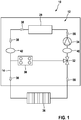
- FIG 1 shows a combustion and / or heating system device 10 in a schematic representation.
- the combustion and / or heating system device 10 preferably comprises at least one fluid circuit 12, in particular a heating water circuit, which has at least one fluid line 14 provided for fluid guidance of a fluid, at least one, in particular digital, pressure sensor 16 for detecting a fluid pressure in the fluid line 14 and at least one control and / or regulating unit 18 (cf. also Figure 2 ).
- the combustion and / or heating system device 10 is preferably designed as a condensing boiler, as a heating value device or as another combustion and / or heating system device which appears to be useful to a person skilled in the art.
- the combustion and / or heating system device 10 preferably comprises further fluid and / or heating-relevant components, such as, for example, a heat cell 28, a heat exchanger 30, a boiler, a buffer store, a solar collector, a valve 32, in particular a three-way valve, a pump 34, a radiator 36 or the like.
- the fluid and / or heating-relevant components at least partially form the fluid circuit 12.
- the components relevant to fluid and / or heating are fluidly connected to one another by the at least one fluid line 14.
- the fluid line 14 is preferably provided for fluid guidance of a fluid designed as water, in particular as heating water.
- the fluid line 14 is provided for a fluid guidance of a fluid designed as a coolant, a fluid as air, in particular heating air, or the like.
- a direction of flow of a fluid within the fluid line 14 is identified by arrows 38.
- Figure 1 is an area 40 of the combustion and / or heating system device 10, in particular of the fluid circuit 12, marked the in Figure 2 is shown.
- the combustion and / or heating system device 10 has, by way of example, a further region 42, which is at least substantially analogous to the region 40. For the sake of clarity, the following description is based on area 40.
- Figure 2 shows part of the combustion and / or heating system device 10 Fig. 1 in a schematic representation.
- the fluid line 14 can preferably be filled with a fluid from a supply network, in particular from a supply network at a location of the combustion and / or heating system device 10, such as, for example, a local water supply network (not shown further here).
- a supply network in particular from a supply network at a location of the combustion and / or heating system device 10, such as, for example, a local water supply network (not shown further here).
- the combustion and / or heating system device 10 and / or the supply network for filling, in particular in a controlled manner, the fluid line 14 with a fluid has at least one filling tap 44.
- the fluid line 14 is designed as a tube, as a hose or as another fluid line which appears to be useful to a person skilled in the art.
- a fluid flowing through the fluid line 14 preferably generates a fluid pressure in the fluid line 14.
- the pressure sensor 16 is preferably set up to measure the fluid pressure in the fluid line 14.
- Pressure sensor 16 is preferably designed as a digital pressure sensor, in particular set up as a function of a detected fluid pressure for outputting digitally processable measured values.
- the pressure sensor 16 is set up to output the measured values in the form of electrical parameters, such as an electrical voltage or an electrical current.
- the pressure sensor 16 is preferably configured differently from an analog, in particular mechanical, pressure sensor.
- the pressure sensor 16 is designed differently from a, in particular analog, manometer.
- the combustion and / or heating system device 10 can preferably have at least one, in particular analogue, manometer 46 in addition to the pressure sensor 16.
- the pressure sensor 16 can in particular be designed as a piezoresistive pressure sensor, as a piezoelectric pressure sensor, as a capacitive pressure sensor, as an inductive pressure sensor or as another pressure sensor which appears to be useful to a person skilled in the art.
- the pressure sensor 16 is preferably arranged at least partially within the fluid line 14, in particular in a secondary branch 48 of the fluid line 14.
- the is preferred Pressure sensor 16 connected to the control and / or regulating unit 18 by means of at least one signal line 50 of the control and / or regulating unit 18, in particular for the transmission of electrical signals.
- the combustion and / or heating system device 10 preferably comprises at least one output unit 20, the control and / or regulating unit 18 being set up to do so, in particular during a filling of the fluid line 14, as a function of a fluid pressure detected by means of the pressure sensor 16, in particular to control a signal output.
- the control and / or regulating unit 18 is preferably set up to control, in particular automatically, the output unit 20.
- the control and / or regulating unit 18 is set up to control and / or regulate further functions and / or components of the combustion and / or heating system device 10, in particular automatically, for example the pump 34 or the valve 32.
- the control and / or regulating unit 18 is preferably connected to the pressure sensor 16 and to the output unit 20 in terms of signal technology.
- the control and / or regulating unit 18 is in particular set up to evaluate the detected fluid pressure during a filling of the fluid line 14 with a fluid, in particular during a first or subsequent filling, and to control the output unit 20 as a function of the evaluation.
- the output unit 20 is preferably set up to output at least one signal, in particular to an operator of the combustion and / or heating system device 10, in particular as a function of activation by the control and / or regulating unit 18.
- the output unit 20 is set up to output at least one signal while the fluid line 14 is being filled, in particular by the operator.
- the operator actuates the filling tap 44 to fill the fluid line 14.
- the dispensing unit 20 is preferably set up, in particular as a function of a control by the control and / or regulating unit 18, the operator is required to actuate, in particular close, the filling tap 44 to signal.
- the output unit 20 is preferably set up to transmit an optical signal, an acoustic signal, a haptic signal, a combination of the aforementioned signal types and / or another, to a person skilled in the art output a signal that appears reasonable. It is conceivable that the control and / or regulating unit 18 is set up to control the output unit 20 in addition to a signal output for activation and / or deactivation. The operator of the combustion and / or heating system device 10 is not shown for the sake of clarity.
- the control and / or regulating unit 18 is preferably set up to activate, in particular to activate, the output unit 20, in particular during a filling of the fluid line 14, as a function of a detected increase in the fluid pressure.
- the fluid pressure in the fluid line 14 increases as a result of fluid additionally flowing into the fluid line 14.
- At least one activation fluid pressure is preferably stored in a storage unit of the control and / or regulating unit 18.
- the control and / or regulating unit 18 is in particular set up to monitor the fluid pressure detected by the pressure sensor 16 continuously or at least at intervals and to compare it with the activation fluid pressure.
- control and / or regulating unit 18 is set up to control, in particular to activate, the output unit 20 as a function of a detected fluid pressure higher than the activation fluid pressure.
- the output unit 20 is preferably set up to output at least one signal as a function of an activation, in particular by the control and / or regulating unit 18, in particular to signal the activation to the operator.
- the output unit 20 is operated manually, for example by means of a switch arranged on the output unit 20, by means of a touch-sensitive button or the like arranged on the output unit 20.
- the output unit 20 has at least one, in particular wireless, communication unit, for example a radio module, a WLAN module, a Bluetooth module or the like, for a signal transmission connection with the external unit.
- the control and / or regulating unit 18 is preferably set up to control the output unit 20, in particular for a signal output, in particular during a filling of the fluid line 14, as a function of a comparison of a detected fluid pressure, in particular fluid limit pressure, with at least one desired fluid pressure.
- the desired fluid pressure in particular a desired fluid pressure range of a plurality of desired fluid pressures, is preferably stored in the storage unit of the control and / or regulating unit 18.
- the desired fluid pressure or the desired fluid pressure range is, in particular, a fluid pressure or a range of a plurality of fluid pressures in the fluid line 14, below or within which the combustion and / or heating system device 10 can be operated, in particular at least essentially without interference with regard to the fluid pressure.
- control and / or regulating unit 18 is set up, in particular during a filling of the fluid line 14, to compare the fluid pressure in the fluid line 14 detected by the pressure sensor 16 continuously or at least intermittently with the target fluid pressure, in particular with a minimum target fluid pressure of the target fluid pressure range.
- a fluid pressure in the fluid line 14 designed as a fluid limit pressure corresponds in particular to the target fluid pressure, in particular the minimum target fluid pressure of the target fluid pressure range.
- the control and / or regulating unit 18 is set up to control the output unit 20 as a function of a detected fluid pressure corresponding to or higher than the desired fluid pressure, in particular the minimum desired fluid pressure of the desired fluid pressure range, in particular for a signal output.
- the output unit 20 is preferably set up to signal the operator in the fluid line 14, in particular as a function of a control by the control and / or regulating unit 18, that the target fluid pressure, in particular the minimum target fluid pressure, of the target fluid pressure range has been reached.
- the output unit 20 is set up to signal an end of the filling to the operator, in particular as a function of activation by the control and / or regulating unit 18.
- the operator preferably closes the filling tap 44 in the fluid line 14 as a result of the fluid target pressure, in particular the minimum fluid target pressure of the fluid target pressure range being reached.
- the output unit 20 is preferably set up to output a different signal, in particular during a filling of the fluid line 14, as a function of a comparison of a detected fluid pressure, in particular a fluid limit pressure, with at least one desired fluid pressure than as a function of a detected increase in the fluid pressure.
- the output unit 20 is set up for this purpose, in particular during a filling of the fluid line 14, depending on a comparison of a detected fluid pressure, in particular fluid limit pressure, with at least one desired fluid pressure, another acoustic signal, another optical signal, another haptic signal or the like. output as a function of a detected increase in fluid pressure.
- the output unit 20 is preferably set up to output different signals from the same type of signals, in particular acoustically, optically or haptically, for example different tones, different colors, different vibration sequences or the like.
- the output unit 20 is set up for this is to output different signals from different types of signals, in particular acoustically, optically or haptically, for example depending on a comparison of a detected fluid pressure, in particular fluid limit pressure, with at least one desired fluid pressure an acoustic signal and depending on a detected increase in fluid pressure an optical signal Signal or the like
- the control and / or regulating unit 18 is preferably set up to activate, in particular to deactivate, the output unit 20, in particular during a filling of the fluid line 14, depending on a detected, at least substantially constant fluid pressure.
- the fluid pressure in the fluid line 14 is at least substantially constant as a result of the filling tap 44 being closed, in particular when the fluid line 14 is in a state free of fluid flowing into the fluid line 14.
- the control and / or regulating unit 18 is preferably set up to compare the detected fluid pressure in the fluid line 14 with a previously detected fluid pressure in the fluid line 14.
- the control and / or regulating unit 18 is preferably set up to control, in particular to deactivate, the output unit 20 as a function of a fluid pressure in the fluid line 14 that is at least substantially change-free, in particular over a predetermined period of time.
- the output unit 20 is set up to be dependent on a deactivation, in particular by the control and / or regulating unit 18, to output at least one signal, in particular to signal the deactivation to the operator.
- the output unit 20 preferably has at least one acoustic output element 22, which is set up to output at least one acoustic signal as a function of activation of the output unit 20 by the control and / or regulating unit 18.
- the acoustic output element 22 is preferably designed as a loudspeaker, as a beeper or the like.
- the acoustic output element 22 is designed as a loudspeaker, for example.
- the output unit 20 can have a plurality of acoustic output elements 22.
- the output unit 20 has, for example, a single acoustic output element 22.
- the acoustic output element 22 is preferably set up to output different acoustic signals as a function of different activations of the output unit 20 by the control and / or regulating unit 18.
- the acoustic output element 22 is set up to output an acoustic signal in the form of a tone, a tone sequence, a beeping, an announcement, a melody or another acoustic signal which appears to be useful to a person skilled in the art.
- the output unit 20, in particular the acoustic output element 22, is preferably connected to the control and / or regulating unit 18 in a wired manner.
- the output unit 20, in particular the acoustic output element 22 is wirelessly connected to the control and / or regulating unit 18, for example as a Bluetooth loudspeaker, as a WLAN loudspeaker or the like.
- the output unit 20 preferably has at least one optical output element 24, which is set up to output at least one optical signal as a function of activation of the output unit 20 by the control and / or regulating unit 18.
- the output unit 20 has the optical output element 24 alternatively or in addition to the acoustic output element 22.
- the output unit 20 has the optical output element 24 as an example in addition to the acoustic output element 22.
- the optical output element is preferably 24 is designed as a lighting element, in particular as an LED, as a screen or the like.
- the optical output element 24 is designed, for example, as an LED.
- the optical output element 24 is preferably configured differently from a graphic output element.
- the optical output element 24 is set up to output optical signals different from graphic representations, in particular text and / or numbers.
- the combustion and / or heating system device 10 comprises a digital display 52, which can be controlled in particular, in particular by the control and / or regulating unit 18, and which is set up to output graphic representations, in particular numerical values of a fluid pressure detected by the pressure sensor 16.
- the output unit 20 can have a plurality of optical output elements 24.
- the output unit 20 has, for example, a single optical output element 24.
- the optical output element 24 is preferably set up to output different optical signals as a function of different activations of the output unit 20 by the control and / or regulating unit 18.
- the optical output element 24 is set up to output an acoustic signal in the form of lighting up, a color, a flashing, a flashing sequence or another optical signal which appears reasonable to a person skilled in the art.
- the output unit 20, in particular the optical output element 24, is preferably connected to the control and / or regulating unit 18 in a wired manner.
- the output unit 20, in particular the optical output element 24, is wirelessly connected to the control and / or regulating unit 18, for example as a wireless screen, in particular of a mobile device, such as, for example, a smartphone or a tablet, or the like. is trained.
- the output unit 20 preferably has at least one vibratory output element 26, which is set up to output at least one haptic signal as a function of activation of the output unit 20 by the control and / or regulating unit 18.
- the output unit 20 has the vibratory output element 26 as an alternative or in addition to the acoustic output element 22 and / or the optical output element 24.
- the output unit 20 has the vibratory output element 26 in addition to the acoustic output element 22 and the optical output element 24.
- the output unit 20 only has the acoustic output element 22, the optical output element 24 or the vibratory output element 26.
- the vibratory output element 26 is preferably designed as a vibration motor, as a vibration alarm or the like.
- the vibratory output element 26 is designed, for example, as a vibration motor.
- the output unit 20 can have a plurality of vibratory output elements 26.
- the output unit 20 has, for example, a single vibratory output element 26.
- the vibratory output element 26 is preferably set up to output different haptic signals as a function of different actuations of the output unit 20 by the control and / or regulating unit 18.
- the vibratory output element 26 is set up to output a haptic signal in the form of a vibration, a vibration sequence or another haptic signal that appears reasonable to a person skilled in the art.
- the output unit 20, in particular the vibratory output element 26, is preferably connected to the control and / or regulating unit 18 in a wired manner.
- the output unit 20, in particular the vibratory output element 26, is wirelessly connected to the control and / or regulating unit 18, for example as a wireless vibration motor, in particular of a mobile device, such as a smartphone or a tablet, or the like. is trained.
- a method for filling a fluid circuit 12 of a combustion and / or heating system device in particular the illustrated combustion and / or heating system device 10, is described.
- at least one method step depending on a detected fluid pressure in at least one fluid line 14 of the fluid circuit 12, at least one output unit 20 of the combustion and / or heating system device 10 is activated, in particular for a signal output.
- the at least one fluid line 14 of the fluid circuit 12 is filled with a fluid.
- the output unit 20 is activated, in particular for a signal output, as a function of a comparison of a detected fluid pressure, in particular a fluid limit pressure, with at least one desired fluid pressure.
Landscapes
- Engineering & Computer Science (AREA)
- Physics & Mathematics (AREA)
- Thermal Sciences (AREA)
- Chemical & Material Sciences (AREA)
- Combustion & Propulsion (AREA)
- Mechanical Engineering (AREA)
- General Engineering & Computer Science (AREA)
- Feeding And Controlling Fuel (AREA)
Applications Claiming Priority (1)
| Application Number | Priority Date | Filing Date | Title |
|---|---|---|---|
| DE102018222726.8A DE102018222726A1 (de) | 2018-12-21 | 2018-12-21 | Brenn- und/oder Heizanlagenvorrichtung |
Publications (1)
| Publication Number | Publication Date |
|---|---|
| EP3671048A1 true EP3671048A1 (fr) | 2020-06-24 |
Family
ID=68531420
Family Applications (1)
| Application Number | Title | Priority Date | Filing Date |
|---|---|---|---|
| EP19208267.5A Withdrawn EP3671048A1 (fr) | 2018-12-21 | 2019-11-11 | Dispositif d'installation de combustion et/ou de chauffage |
Country Status (2)
| Country | Link |
|---|---|
| EP (1) | EP3671048A1 (fr) |
| DE (1) | DE102018222726A1 (fr) |
Citations (6)
| Publication number | Priority date | Publication date | Assignee | Title |
|---|---|---|---|---|
| DE9406048U1 (de) * | 1994-04-12 | 1994-06-16 | Henkenjohann, Walter, 33415 Verl | Vorrichtung zum automatischen Nachfüllen von Heizungsanlagen |
| DE29924189U1 (de) * | 1999-01-13 | 2002-04-04 | Zimmermann, Ulrich, 18109 Rostock | Füllschlauch mit funkgesteuerter Füllarmatur mit Fernbedienung |
| EP1832816A2 (fr) * | 2006-03-09 | 2007-09-12 | ELTEK S.p.A. | Dispositif hydraulique, appareil hydraulique, système hydraulique et son procédé d'utilisation |
| WO2015143527A1 (fr) * | 2014-03-26 | 2015-10-01 | Martino Contractors Ltd. | Dispositif de surveillance pour un appareil de chauffage au gaz naturel |
| EP2975485A1 (fr) * | 2014-07-15 | 2016-01-20 | Orkli, S. Coop. | Ensemble de vannes adapté pour réaliser la connexion automatique d'un réseau d'alimentation en eau à un circuit primaire |
| WO2018111881A1 (fr) * | 2016-12-15 | 2018-06-21 | Stevens Lee Hiram | Notification et arrêt de perte de fluide pour un système de transfert de chaleur de fluide en boucle fermée |
-
2018
- 2018-12-21 DE DE102018222726.8A patent/DE102018222726A1/de not_active Withdrawn
-
2019
- 2019-11-11 EP EP19208267.5A patent/EP3671048A1/fr not_active Withdrawn
Patent Citations (6)
| Publication number | Priority date | Publication date | Assignee | Title |
|---|---|---|---|---|
| DE9406048U1 (de) * | 1994-04-12 | 1994-06-16 | Henkenjohann, Walter, 33415 Verl | Vorrichtung zum automatischen Nachfüllen von Heizungsanlagen |
| DE29924189U1 (de) * | 1999-01-13 | 2002-04-04 | Zimmermann, Ulrich, 18109 Rostock | Füllschlauch mit funkgesteuerter Füllarmatur mit Fernbedienung |
| EP1832816A2 (fr) * | 2006-03-09 | 2007-09-12 | ELTEK S.p.A. | Dispositif hydraulique, appareil hydraulique, système hydraulique et son procédé d'utilisation |
| WO2015143527A1 (fr) * | 2014-03-26 | 2015-10-01 | Martino Contractors Ltd. | Dispositif de surveillance pour un appareil de chauffage au gaz naturel |
| EP2975485A1 (fr) * | 2014-07-15 | 2016-01-20 | Orkli, S. Coop. | Ensemble de vannes adapté pour réaliser la connexion automatique d'un réseau d'alimentation en eau à un circuit primaire |
| WO2018111881A1 (fr) * | 2016-12-15 | 2018-06-21 | Stevens Lee Hiram | Notification et arrêt de perte de fluide pour un système de transfert de chaleur de fluide en boucle fermée |
Also Published As
| Publication number | Publication date |
|---|---|
| DE102018222726A1 (de) | 2020-06-25 |
Similar Documents
| Publication | Publication Date | Title |
|---|---|---|
| EP2815131B1 (fr) | Procédé de fonctionnement d'un générateur de succion et dispositif de générateur de succion | |
| DE102011012558B3 (de) | Druckluft-Wartungsgerät und damit ausgestattete Verbrauchersteuervorrichtung | |
| EP3034955A1 (fr) | Procédé d'exécution d'un équilibrage hydraulique automatisé d'une installation de chauffage | |
| DE102010054979A1 (de) | Ventilanordnung und Verfahren zum Betätigen eines Ventils | |
| EP3242033A1 (fr) | Procédé de fonctionnement d'un groupe motopompe à commande électrique | |
| EP2908059B1 (fr) | Procédé de diagnostic d'une installation de chauffage doté d'au moins un échangeur thermique | |
| CN104085304B (zh) | 基于缓速器的车速限制方法以及车速限制系统 | |
| EP3671048A1 (fr) | Dispositif d'installation de combustion et/ou de chauffage | |
| DE212017000161U1 (de) | System zur Automatisierung des Einschaltens, Einstellens und/oder Ausschaltens eines oder mehrerer Zubehörteile für Kochfelder | |
| DE102015207710B4 (de) | Verfahren zur Erhöhung der Genauigkeit einer sensorlosen Druckerfassung | |
| EP3647600B1 (fr) | Identification d'un périphérique connecté électriquement | |
| EP1518075A1 (fr) | Appareil menager, notamment appareil de cuisson dote d'une unite de memoire | |
| EP3260795B1 (fr) | Dispositif d'appareil de chauffage | |
| EP3234325A1 (fr) | Procédé pour faire fonctionner un moteur à combustion interne | |
| DE102014226620A1 (de) | Verfahren und Vorrichtung zur Parametrierung zumindest einer Komponente einer elektrohydraulischen Antriebseinheit | |
| EP2108896A2 (fr) | Système de chauffage d'eau | |
| DE102014103367A1 (de) | Regelsystem | |
| EP3592980A1 (fr) | Procédé pour faire fonctionner une pompe de circulation et pompe de circulation pour mettre en oeuvre ce procédé | |
| DE102021202800A1 (de) | Verfahren zu einem hydraulischen Abgleich eines Fluidkreislaufs | |
| EP3483449A1 (fr) | Procédé de surveillance d'une pompe centrifuge à régulation électronique | |
| DE102010001199A1 (de) | Steuereinrichtung für eine Heizungseinrichtung und System zur Steuerung einer Heizungsanlage | |
| DE102021209288A1 (de) | Verfahren zum Steuern eines Heizungssystems, Heizungssysteme und Steuervorrichtungen zum Steuern eines Heizungssystems | |
| DE102005008171B4 (de) | Ultraschall-Sensor zur berühungslosen Entfernungsmessung zur erleichteterten Darstellung von veränderbaren Informationen | |
| DE102016225408A1 (de) | Fluidvorrichtung und Verfahren zur Überwachung einer Fluidvorrichtung | |
| DE102004057175A1 (de) | Betätigungsvorrichtung für eine sanitäre, insbesondere elektronische, Temperierarmatur und Verfahren zum Betreiben einer solchen |
Legal Events
| Date | Code | Title | Description |
|---|---|---|---|
| PUAI | Public reference made under article 153(3) epc to a published international application that has entered the european phase |
Free format text: ORIGINAL CODE: 0009012 |
|
| STAA | Information on the status of an ep patent application or granted ep patent |
Free format text: STATUS: THE APPLICATION HAS BEEN PUBLISHED |
|
| AK | Designated contracting states |
Kind code of ref document: A1 Designated state(s): AL AT BE BG CH CY CZ DE DK EE ES FI FR GB GR HR HU IE IS IT LI LT LU LV MC MK MT NL NO PL PT RO RS SE SI SK SM TR |
|
| AX | Request for extension of the european patent |
Extension state: BA ME |
|
| STAA | Information on the status of an ep patent application or granted ep patent |
Free format text: STATUS: THE APPLICATION IS DEEMED TO BE WITHDRAWN |
|
| 18D | Application deemed to be withdrawn |
Effective date: 20210112 |