EP1833075A1 - Tube a rayons x et source de rayons x - Google Patents
Tube a rayons x et source de rayons x Download PDFInfo
- Publication number
- EP1833075A1 EP1833075A1 EP05814312A EP05814312A EP1833075A1 EP 1833075 A1 EP1833075 A1 EP 1833075A1 EP 05814312 A EP05814312 A EP 05814312A EP 05814312 A EP05814312 A EP 05814312A EP 1833075 A1 EP1833075 A1 EP 1833075A1
- Authority
- EP
- European Patent Office
- Prior art keywords
- valve
- ray tube
- end side
- support body
- target support
- Prior art date
- Legal status (The legal status is an assumption and is not a legal conclusion. Google has not performed a legal analysis and makes no representation as to the accuracy of the status listed.)
- Granted
Links
Images



Classifications
-
- H—ELECTRICITY
- H01—ELECTRIC ELEMENTS
- H01J—ELECTRIC DISCHARGE TUBES OR DISCHARGE LAMPS
- H01J35/00—X-ray tubes
- H01J35/02—Details
- H01J35/04—Electrodes ; Mutual position thereof; Constructional adaptations therefor
- H01J35/08—Anodes; Anti cathodes
-
- H—ELECTRICITY
- H01—ELECTRIC ELEMENTS
- H01J—ELECTRIC DISCHARGE TUBES OR DISCHARGE LAMPS
- H01J35/00—X-ray tubes
- H01J35/02—Details
- H01J35/04—Electrodes ; Mutual position thereof; Constructional adaptations therefor
- H01J35/08—Anodes; Anti cathodes
- H01J35/112—Non-rotating anodes
-
- H—ELECTRICITY
- H01—ELECTRIC ELEMENTS
- H01J—ELECTRIC DISCHARGE TUBES OR DISCHARGE LAMPS
- H01J35/00—X-ray tubes
- H01J35/02—Details
- H01J35/16—Vessels; Containers; Shields associated therewith
-
- H—ELECTRICITY
- H05—ELECTRIC TECHNIQUES NOT OTHERWISE PROVIDED FOR
- H05G—X-RAY TECHNIQUE
- H05G1/00—X-ray apparatus involving X-ray tubes; Circuits therefor
- H05G1/02—Constructional details
- H05G1/04—Mounting the X-ray tube within a closed housing
- H05G1/06—X-ray tube and at least part of the power supply apparatus being mounted within the same housing
-
- H—ELECTRICITY
- H01—ELECTRIC ELEMENTS
- H01J—ELECTRIC DISCHARGE TUBES OR DISCHARGE LAMPS
- H01J2235/00—X-ray tubes
- H01J2235/10—Drive means for anode (target) substrate
- H01J2235/1006—Supports or shafts for target or substrate
Definitions
- the present invention relates to an X-ray tube to be incorporated in, for example, an X-ray generator for use in nondestructive tests and an X-ray source using the same.
- X-ray tubes are for bringing electrons emitted from an electron gun into collision with a target to generate X-rays.
- This X-ray tube includes a vacuum enclosure with a valve joining the enclosure main body for housing an electron gun, in the vacuum enclosure inserted is a target support body for supporting a target therein.
- the valve is formed with an inner cylindrical portion in a way that the leading end portion thereof is folded wholly inward, and the leading end portion of the inner cylindrical portion is fixed to the target support body.
- the target support body is provided with a cover for covering the fixation portion where the target support body and the leading end portion of the inner cylindrical portion are fixed to each other to suppress the generation of discharge in the valve.
- Patent Document 1 U.S. Patent No. 5,077,771
- the present invention has been made to solve the above-described problems, and an object thereof is to provide an X-ray tube in which the generation of discharge in a valve can be suppressed with a simple structure and an X-ray source using the same.
- the present invention is directed to an X-ray tube for bringing electrons emitted from an electron gun into collision with a target to generate X-rays, including: an enclosure main body for housing therein the electron gun; a cylindrical valve with an opening portion on one end side thereof being fixed to the enclosure main body, while the other end portion thereof being formed as a narrowed portion; and a target support body inserted in the valve to support the target, in which an opening portion on the other end side of the valve is fixed to the target support body, and a shield portion is formed between the enclosure main body and the opening portion on the other end side, the shield portion being adapted to shield a fixation portion where the target support body and the opening portion on the other end side are fixed to each other when viewed from the one end side of the valve.
- the shield portion is formed between the enclosure main body and the opening portion on the other end side of the valve, the shield portion being adapted to shield the fixation portion where the target support body and the opening portion on the other end side are fixed to each other when viewed from the one end side of the valve. This can suppress the generation of discharge between the one end side of the valve and the fixation portion where the target support body and the opening portion on the other end side are fixed to each other.
- the other end portion of the valve is formed as a narrowed portion and the opening portion on the other end side of the valve is fixed to the target support body, whereby the shapes of the valve and the shield portion can be made simpler than in the conventional X-ray tube in which the inner cylindrical portion is formed in the valve.
- Such a simple structure can achieve an effective suppression of the generation of discharge. Further, when fixing the target support body and the opening portion on the other end side of the valve, workability and visibility are increased relative to the conventional X-ray tube in which the inner cylindrical portion is formed in the valve, which can also enhance the reliability of X-ray tubes manufactured.
- the shield portion is preferably formed integrally with the target support body. In this case, since the number of parts in the valve is reduced, the generation of discharge in the valve can be suppressed more effectively.
- the shield portion is preferably formed to have rounded corner portions or have no corner portion. Since this can prevent an electric field from being concentrated locally in the shield portion, the generation of discharge can be suppressed more effectively.
- the X-ray tube includes a cylindrical member joining the opening portion on the other end side in which the target support body is inserted, wherein the opening portion on the other end side is fixed to the target support body via the cylindrical member.
- the present invention is directed to an X-ray source including a chassis for housing therein the above-described X-ray tube and a high-voltage power supply unit for supplying a voltage to the target support body in the X-ray tube, in which the portion where the target support body and the opening portion on the other end side are fixed to each other is surrounded by a surrounding member.
- the chassis includes an insulating block with the high-voltage power supply unit embedded therein, and a metallic cylindrical portion fixed to the insulating block and filled with insulating liquid material inside, and wherein the valve in the X-ray tube is housed in the cylindrical portion, and the surrounding member surrounds the fixation portion in such a manner that the fixation portion is not seen through from an inner wall of the cylindrical portion.
- the surrounding member has a wall portion extending along a tube axis direction of the X-ray tube, and that the wall portion surrounds the fixation portion in such a manner that the fixation portion is not seen through from the inner wall of the cylindrical portion.
- the generation of discharge in the valve can be suppressed with a simple structure.
- 1 X-ray source
- 2 Chassis
- 3 High-voltage power supply unit
- 4 X-ray tube
- 18 Target support body
- 19 Enclosure main body
- 20 Valve
- 32 Opening portion on one end side
- 34 Opening portion on the other end side
- 37 Narrowed portion (other end portion)
- 40, 40A, 40B, 41, and 41A Cylindrical members
- 42 and 42A Shield portions
- 42a Corner portion
- T Target
- W Fixation portion
- Fig.1 is a cross-sectional view of an X-ray source according to an embodiment of the present invention.
- the X-ray source 1 includes a chassis 2, a high-voltage power supply unit 3, and an X-ray tube 4.
- the chassis 2 is comprised of a bottom plate 6, a top plate 7, a cylindrical portion 8, and an insulating block 9.
- the bottom plate 6 and top plate 7 each have an approximately square shape, and a circular through hole 7a is provided in the center of the top plate 7.
- the corners of the bottom plate 6 and top plate 7 are coupled to each other via spacers 10, and the bottom plate 6 and top plate 7 are fixed to each other with a predetermined spacing therebetween.
- the bottom plate 6, top plate 7, and the side surfaces of the spacers 10 are covered with side plates (not shown in the drawings) for joining these components.
- the cylindrical portion 8 is formed of metal in a circular cylindrical shape with the upper end thereof being tapered, the inside diameter thereof being the same as that of the through hole 7a in the top plate 7.
- An installation flange 8a is provided in the lower end portion of the cylindrical portion 8, while a circular opening portion 8b for mounting the X-ray tube 4 thereon is formed in the upper end portion.
- the cylindrical portion 8 is erected in the center of the upper surface of the top plate 7 in such a manner that the inside of the cylindrical portion 8 communicates with the through hole 7a in the top plate 7 by fixing the installation flange 8a liquid-tightly to the peripheral edge portion of the through hole 7a in the top plate 7. It is noted that the cylindrical portion 8 has a ground potential.
- the insulating block 9 is formed of insulating resin material such as epoxy resin in an approximately cubic shape, the surface thereof being processed to be covered with conductive material to have a ground potential, such as applying of conductive tape or conductive coating.
- the insulating block 9 is held between the bottom plate 6 and top plate 7 in such a manner as to cover the through hole 7a in the top plate 7 from below.
- a housing space S surrounded by the cylindrical portion 8, top plate 7, insulating block 9, and high-voltage power supply unit 3 is formed in the upper part of the chassis 2. It is noted that the housing space S is filled with insulating liquid material such as insulating oil 11.
- the X-ray tube 4 is fixed liquid-tightly to the opening portion 8b of the cylindrical portion 8 with a valve 20 to be described hereinafter being housed in the housing space S. Also, the leading end portion of a target support body 18 that protrudes from an opening portion 34 on the other end side of the valve 20 (refer to Fig.2) is fixed with screws to a high-voltage cap (surrounding member) 12 for surrounding the fixation portion W where the opening portion 34 on the other end side and the target support body 18 are fixed to each other.
- a high-voltage cap surrounding member
- the high-voltage cap 12 is made of conductive material (e.g. aluminum) and surrounds a portion where to seal the valve 20 which is positioned in the vicinity of the leading end portion on the high-voltage power supply unit 3 side of the target support body 18.
- the high-voltage cap 12 has a circular bottom plate portion 12b and a wall portion 12a erected on its edge, the central axis thereof being fixed coaxially with the tube axis of the X-ray tube 4.
- the inside diameter of the wall portion 12a is at least greater than the outside diameter of the valve 20 in the vicinity of the fixation portion W.
- the wall portion 12a extends along the tube axis direction of the X-ray tube 4.
- the wall portion 12a shields the fixation portion W in such a manner that the fixation portion W is not seen through from the inner wall of the cylindrical portion 8.
- the high-voltage cap 12 also has the bottom plate portion 12b and is fixed coaxially to the target support body 18 with screws in such a manner as to sandwich the bottom plate portion 12b, but may be fixed from the wall portion 12a side with screws so as to intersect with the axial direction of the target support body 18. In this case, the bottom plate portion 12b may not be provided.
- the high-voltage power supply unit 3 is embedded in the center in the upper part of the insulating block 9 and is arranged beneath the through hole 7a in the top plate 7.
- the high-voltage power supply unit 3 is connected electrically to the target support body 18 via a compression spring 13 with one end thereof being supported by the high-voltage cap 12 and is adapted to supply a high voltage to the target support body 18 via the compression spring 13 and the high-voltage cap 12.
- Fig.2 is a cross-sectional view of the X-ray tube 4.
- the X-ray tube 4 includes a vacuum enclosure 16, an electron gun 17, and target support body 18.
- the vacuum enclosure 16 is comprised of enclosure main body 19 and valve 20.
- the metallic enclosure main body 19 is comprised of a trunk portion 21 for housing therein a target T as an anode and an electron gun housing portion 22 for housing therein the electron gun 17 as a cathode.
- the trunk portion 21 is formed of metal in an approximately circular cylindrical shape to have an internal space R.
- a flange portion 21a to be used for fixation to the opening portion 8b of the cylindrical portion 8 in the X-ray source 1.
- a cover plate 24 with an output window 23 fixed thereto, the cover plate 24 covering the lower end side of the internal space R.
- the electron gun housing portion 22 is formed of metal in a cross-sectionally circular cylindrical shape and joins the lower side of the trunk portion 21 air-tightly in a direction perpendicular to the trunk portion 21.
- the portion where the electron gun housing portion 22 and the trunk portion 21 are joined is provided with an aperture 26 that provides communication between the inside of the electron gun housing portion 22 and the internal space R of the trunk portion 21 and serves as a convergence electrode, and a stem substrate 27 is fixed to the end portion on the opposite side of the aperture 26.
- the electron gun 17 is composed of a cathode C, a heater 28, a first grid electrode 29, and a second grid electrode 30, these components being fixed to the stem substrate 27 via a plurality of stem pins 31.
- Each stem pin 31 is connected to an external power supply (not shown in the drawings) to supply a predetermined voltage to the electron gun 17.
- the valve 20 is formed of insulating material such as glass or ceramic in an approximately circular cylindrical shape with a diameter of about 50mm.
- a metallic ring member 33 joins an opening portion 32 on the one end side of the valve 20 by fusion bonding, the opening portion 32 on the one end side joining the trunk portion 21 via the ring member 33 in such a manner that the upper end portion 21b of the trunk portion 21 is arranged inside the valve 20.
- the target support body 18 is formed of metal such as copper material in a rod shape with a diameter of about 15mm, and the target T is embedded in an inclined surface 18c that is formed in one end portion 18a of the body.
- the one end portion 18a of the target support body 18 is arranged in the internal space R of the trunk portion 21 in the enclosure main body 19 through the opening portion 32 on the one end side of the valve 20 in such a manner that the target T faces the electron gun 17 in the internal space R.
- the target support body 18 may be formed integrally with the target T using the same material as the target T.
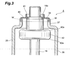
- the other end portion of the valve 20 which has a diameter smaller than the outside diameter of the main body portion 36 of the valve 20, is formed stepwise as a narrowed portion 37 with a diameter of about 25mm in such a manner as to protrude from the main body portion 36. Then, the upper end of the narrowed portion 37 forms the opening portion 34 on the other end side of the valve 20. Also, a cylindrical member 40 made of metal such as kovar joins the opening portion 34 on the other end side of the valve 20 by fusion bonding.
- the upper end side of the cylindrical member 40 is formed stepwise to have a smaller diameter correspondingly to the outside diameter of the target support body 18, and a cylindrical member 41 made of metal such as kovar is fixed by welding to the inside of the smaller diameter portion for insertion of the other end portion 18b of the target support body 18. Then, the opening portion 34 on the other end side of the valve 20 is sealed by being fixed to the other end portion 18b of the target support body 18 via the cylindrical members 40 and 41.
- the target support body 18 is further formed integrally with a metallic shield portion 42 in the vicinity of the narrowed portion 37 of the valve 20.
- the shield portion 42 has a circular disk shape with a diameter of about 30mm with the major diameter (maximum diameter here) thereof being smaller than that of the main body portion 36 of the valve 20 but greater than that of the narrowed portion 37, and each corner portion 42a is chamfered and rounded.
- the shield portion 42 shields the fixation portion W where the other end portion 18b of the target support body 18 and the opening portion 34 on the other end side of the valve 20 are fixed to each other when viewed from the one end side of the valve 20, and particularly, the shield portion 42 shields the portion where the opening portion 34 on the other end side and the cylindrical member 40 are joined, that is, the sealed portion where insulating material and metal are joined in such a manner that the sealed portion is not seen through from the upper end portion 21b of the trunk portion 21 in the enclosure main body 19.
- the shield portion 42 is formed between the enclosure main body 19 and the opening portion 34 on the other end side of the valve 20, the shield portion 42 being adapted to shield the fixation portion W where the target support body 18 and the opening portion 34 on the other end side are fixed to each other when viewed from the one end side of the valve 20. This can suppress the generation of discharge between the one end side of the valve 20 and the fixation portion W.
- the other end portion of the valve 20 is formed as a narrowed portion 37 and the opening portion 34 on the other end side of the valve 20 is fixed to the target support body 18, whereby the shapes of the valve 20 and the shield portion 42 can be made simpler than in conventional X-ray tubes in which an inner cylindrical portion is formed in a valve.
- Such a simple structure can improve the stability of an electric field in the valve 20 when generating X-rays and thereby achieve an effective suppression of the generation of discharge in the valve 20, and further can improve the radiation performance as well as reduce residual gas.
- each corner portion 42a of the shield portion 42 is chamfered and rounded, which can prevent an electric field from being concentrated locally when generating X-rays. These result in suppressing the generation of discharge in the valve 20 more effectively.
- the target support body 18 and the opening portion 34 on the other end side of the valve 20 are joined via the cylindrical members 40 and 41.
- the cylindrical member 40 is fusion bonded to the opening portion 34 on the other end side and the cylindrical member 41 is welded to the other end portion 18b of the target support body 18 in advance, and finally the cylindrical members 40 and 41 are welded to each other, for example.
- the target support body 18 can be fine-adjusted axially along the cylindrical member 40 when the cylindrical members 40 and 41 are welded, which allows the target T to be aligned accurately with respect to the electron gun 17.
- the fixation portion W where the opening portion 34 on the other end side of the valve 20 and the target support body 18 are fixed to each other is surrounded and shielded by the high-voltage cap 12 so as not to be seen through from the inner wall of the cylindrical portion 8. This can suppress the generation of discharge between the X-ray tube 4 and the inner wall of the cylindrical portion 8 when generating X-rays.
- the cylindrical portion 8 is fixed to the insulating block 9, the valve 20 in the X-ray tube 4 is housed in the cylindrical portion 8, and the high-voltage cap 12 surrounds the fixation portion W in such a manner that the fixation portion W is not seen through from the inner wall of the cylindrical portion 8. Since this can improve the radiation performance of the X-ray tube 4 when generating X-rays, the generation of discharge in the X-ray tube 4 can be suppressed. In addition, since the high-voltage cap 12 surrounds the fixation portion W, the generation of discharge between the X-ray tube 4 and the inner wall of the cylindrical portion 8 can be suppressed.
- the high-voltage cap 12 has the wall portion 12a that extends along the tube axis direction of the X-ray tube 4, and the wall portion 12a surrounds the fixation portion W in such a manner that the fixation portion W is not seen through from the inner wall of the cylindrical portion 8. Thus, an electric field in the vicinity of the fixation portion W cannot be disturbed, whereby the generation of discharge can be suppressed more effectively.
- the present invention is not restricted to the above-described embodiment, and various modifications may be made.
- the shield portion 42 has a circular disk shape with each corner portion 42a being chamfered and rounded in an R-shape in the above-described embodiment, the shield portion may have a shape with no corner portion such as spherical or ellipsoidal.
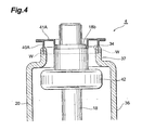
- cylindrical members 40A and 41 A each having a flange may be employed as cylindrical members.
- the flanges of the cylindrical members 40A and 41A can be overlapped and fixed to each other by welding.
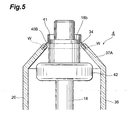
- the other end portion of the valve 20 may be formed as a narrowed portion 37A with the diameter thereof being reduced in a tapered manner.
- the narrowed portion 37A may be combined with a shield portion 42A that is formed with the diameter thereof being increased gradually from one end side to the other end side of the target support body 18.
- the maximum diameter of the shield portion 42A is preferably smaller than that of the main body portion 36 of the valve 20 but greater than that of the fixation portion W at the narrowed portion 37A. Also in these exemplary variations, the same effects as in the above-described embodiment can be obtained.
Landscapes
- X-Ray Techniques (AREA)
Applications Claiming Priority (2)
| Application Number | Priority Date | Filing Date | Title |
|---|---|---|---|
| JP2004377775 | 2004-12-27 | ||
| PCT/JP2005/022694 WO2006070586A1 (fr) | 2004-12-27 | 2005-12-09 | Tube a rayons x et source de rayons x |
Publications (3)
| Publication Number | Publication Date |
|---|---|
| EP1833075A1 true EP1833075A1 (fr) | 2007-09-12 |
| EP1833075A4 EP1833075A4 (fr) | 2009-02-25 |
| EP1833075B1 EP1833075B1 (fr) | 2011-02-16 |
Family
ID=36614707
Family Applications (1)
| Application Number | Title | Priority Date | Filing Date |
|---|---|---|---|
| EP05814312A Expired - Lifetime EP1833075B1 (fr) | 2004-12-27 | 2005-12-09 | Tube a rayons x et source de rayons x |
Country Status (8)
| Country | Link |
|---|---|
| US (1) | US7773726B2 (fr) |
| EP (1) | EP1833075B1 (fr) |
| JP (1) | JP4712727B2 (fr) |
| KR (1) | KR101001428B1 (fr) |
| CN (2) | CN102201320B (fr) |
| DE (1) | DE602005026450D1 (fr) |
| TW (1) | TWI351707B (fr) |
| WO (1) | WO2006070586A1 (fr) |
Families Citing this family (18)
| Publication number | Priority date | Publication date | Assignee | Title |
|---|---|---|---|---|
| JP4369923B2 (ja) | 2003-07-22 | 2009-11-25 | ポニー工業株式会社 | 透過撮影装置 |
| KR100802443B1 (ko) * | 2006-01-17 | 2008-02-13 | 포니 고교 가부시키가이샤 | 투과촬영장치 |
| JP4691170B2 (ja) * | 2008-03-04 | 2011-06-01 | 株式会社ジョブ | X線照射装置 |
| JP5021716B2 (ja) * | 2009-12-02 | 2012-09-12 | マイクロXジャパン株式会社 | X線発生装置及び携帯型非破壊検査装置 |
| JP5927665B2 (ja) * | 2011-11-30 | 2016-06-01 | 高砂熱学工業株式会社 | 電界放出型x線発生装置 |
| CN102595754B (zh) * | 2012-01-06 | 2015-05-13 | 同方威视技术股份有限公司 | 辐射器件安装箱、油冷循环系统以及x射线发生器 |
| JP5835845B2 (ja) * | 2012-07-18 | 2015-12-24 | 株式会社リガク | 非破壊検査用の工業用x線発生装置 |
| DE102015213810B4 (de) * | 2015-07-22 | 2021-11-25 | Siemens Healthcare Gmbh | Hochspannungszuführung für einen Röntgenstrahler |
| WO2018078676A1 (fr) * | 2016-10-31 | 2018-05-03 | キヤノンアネルバ株式会社 | Générateur de rayons x et système de radiographie |
| JP7044615B2 (ja) * | 2018-04-12 | 2022-03-30 | 浜松ホトニクス株式会社 | X線管 |
| USD882091S1 (en) | 2018-04-12 | 2020-04-21 | Hamamatsu Photonics K.K. | X-ray generating apparatus |
| JP7112235B2 (ja) * | 2018-04-12 | 2022-08-03 | 浜松ホトニクス株式会社 | X線管 |
| JP6543378B1 (ja) * | 2018-04-12 | 2019-07-10 | 浜松ホトニクス株式会社 | X線発生装置 |
| US10748740B2 (en) * | 2018-08-21 | 2020-08-18 | Fei Company | X-ray and particle shield for improved vacuum conductivity |
| JP7337577B2 (ja) * | 2019-07-24 | 2023-09-04 | 浜松ホトニクス株式会社 | X線管、及びx線発生装置 |
| US11585768B1 (en) * | 2021-08-24 | 2023-02-21 | Neuf Inc. | System and method for inspecting defects of structure by using x-ray |
| US11972920B2 (en) | 2021-11-23 | 2024-04-30 | Fei Company | Vacuum compatible X-ray shield |
| KR102939956B1 (ko) * | 2023-12-06 | 2026-03-18 | 주식회사 고영테크놀러지 | X선관 및 이를 포함하는 시스템 |
Family Cites Families (18)
| Publication number | Priority date | Publication date | Assignee | Title |
|---|---|---|---|---|
| US2431277A (en) * | 1944-02-03 | 1947-11-18 | Hartford Nat Bank & Trust Comp | Metal-glass joint |
| US2845559A (en) | 1953-10-09 | 1958-07-29 | Westinghouse Electric Corp | Structure for high voltage tube |
| JPS3728601Y1 (fr) * | 1960-05-30 | 1962-10-23 | ||
| JPS5092669A (fr) * | 1973-12-13 | 1975-07-24 | ||
| JPS5513889Y2 (fr) * | 1973-12-28 | 1980-03-28 | ||
| US4184097A (en) * | 1977-02-25 | 1980-01-15 | Magnaflux Corporation | Internally shielded X-ray tube |
| DE2855905A1 (de) * | 1978-12-23 | 1980-06-26 | Licentia Gmbh | Vorrichtung mit einer roentgenroehre |
| JPH0665189B2 (ja) * | 1986-05-02 | 1994-08-22 | 株式会社日立メディコ | 軸受の寿命判定装置を備えたx線管 |
| US5077771A (en) * | 1989-03-01 | 1991-12-31 | Kevex X-Ray Inc. | Hand held high power pulsed precision x-ray source |
| JPH08129980A (ja) * | 1994-10-28 | 1996-05-21 | Shimadzu Corp | X線管用陽極 |
| DE19536247C2 (de) * | 1995-09-28 | 1999-02-04 | Siemens Ag | Röntgenröhre |
| DE19630351C1 (de) * | 1996-07-26 | 1997-11-27 | Siemens Ag | Röntgenröhre mit einem Gleitlager |
| JP4015256B2 (ja) * | 1998-02-06 | 2007-11-28 | 浜松ホトニクス株式会社 | X線管 |
| JP4216394B2 (ja) * | 1999-03-15 | 2009-01-28 | 株式会社東芝 | X線管装置 |
| JP4068332B2 (ja) | 2001-10-19 | 2008-03-26 | 浜松ホトニクス株式会社 | X線管、及び、x線管の製造方法 |
| JP4216579B2 (ja) * | 2002-12-26 | 2009-01-28 | 浜松ホトニクス株式会社 | X線源 |
| JP3728601B2 (ja) | 2003-06-18 | 2005-12-21 | 日本航空電子工業株式会社 | カード用コネクタ |
| US7031433B2 (en) * | 2004-02-27 | 2006-04-18 | Hamamatsu Photonics K.K. | X-ray source and a nondestructive inspector |
-
2005
- 2005-12-09 CN CN2011100923361A patent/CN102201320B/zh not_active Expired - Lifetime
- 2005-12-09 KR KR1020077005370A patent/KR101001428B1/ko not_active Expired - Lifetime
- 2005-12-09 EP EP05814312A patent/EP1833075B1/fr not_active Expired - Lifetime
- 2005-12-09 US US11/793,306 patent/US7773726B2/en not_active Expired - Lifetime
- 2005-12-09 JP JP2006550654A patent/JP4712727B2/ja not_active Expired - Lifetime
- 2005-12-09 CN CN2005800412119A patent/CN101069259B/zh not_active Expired - Lifetime
- 2005-12-09 WO PCT/JP2005/022694 patent/WO2006070586A1/fr not_active Ceased
- 2005-12-09 DE DE602005026450T patent/DE602005026450D1/de not_active Expired - Lifetime
- 2005-12-15 TW TW094144389A patent/TWI351707B/zh active
Also Published As
| Publication number | Publication date |
|---|---|
| JP4712727B2 (ja) | 2011-06-29 |
| CN101069259B (zh) | 2011-06-08 |
| EP1833075A4 (fr) | 2009-02-25 |
| TW200634883A (en) | 2006-10-01 |
| WO2006070586A1 (fr) | 2006-07-06 |
| DE602005026450D1 (de) | 2011-03-31 |
| EP1833075B1 (fr) | 2011-02-16 |
| CN102201320B (zh) | 2012-11-28 |
| KR101001428B1 (ko) | 2010-12-14 |
| JPWO2006070586A1 (ja) | 2008-06-12 |
| KR20070101203A (ko) | 2007-10-16 |
| CN102201320A (zh) | 2011-09-28 |
| US7773726B2 (en) | 2010-08-10 |
| TWI351707B (en) | 2011-11-01 |
| US20080107237A1 (en) | 2008-05-08 |
| CN101069259A (zh) | 2007-11-07 |
Similar Documents
| Publication | Publication Date | Title |
|---|---|---|
| EP1833075B1 (fr) | Tube a rayons x et source de rayons x | |
| KR102760595B1 (ko) | X선관 | |
| CN101283432A (zh) | X射线管和包含其的x射线源 | |
| CN101283433B (zh) | X射线管及包含其的x射线源 | |
| KR101240779B1 (ko) | X선관 및 이를 포함하는 x선원 | |
| KR101237545B1 (ko) | X선관 및 이를 포함하는 x선원 | |
| CN110379696B (zh) | X射线管 | |
| CN101283435B (zh) | X射线管以及包含其的x射线源 | |
| TW202111754A (zh) | X光管及x光產生裝置 |
Legal Events
| Date | Code | Title | Description |
|---|---|---|---|
| PUAI | Public reference made under article 153(3) epc to a published international application that has entered the european phase |
Free format text: ORIGINAL CODE: 0009012 |
|
| 17P | Request for examination filed |
Effective date: 20070608 |
|
| AK | Designated contracting states |
Kind code of ref document: A1 Designated state(s): DE FR |
|
| DAX | Request for extension of the european patent (deleted) | ||
| RBV | Designated contracting states (corrected) |
Designated state(s): DE FR |
|
| A4 | Supplementary search report drawn up and despatched |
Effective date: 20090126 |
|
| 17Q | First examination report despatched |
Effective date: 20090212 |
|
| GRAP | Despatch of communication of intention to grant a patent |
Free format text: ORIGINAL CODE: EPIDOSNIGR1 |
|
| RIN1 | Information on inventor provided before grant (corrected) |
Inventor name: INAZURU, TUTOMU,C/O HAMAMATSU PHOTONICS K.K. |
|
| GRAS | Grant fee paid |
Free format text: ORIGINAL CODE: EPIDOSNIGR3 |
|
| GRAA | (expected) grant |
Free format text: ORIGINAL CODE: 0009210 |
|
| AK | Designated contracting states |
Kind code of ref document: B1 Designated state(s): DE FR |
|
| REF | Corresponds to: |
Ref document number: 602005026450 Country of ref document: DE Date of ref document: 20110331 Kind code of ref document: P |
|
| REG | Reference to a national code |
Ref country code: DE Ref legal event code: R096 Ref document number: 602005026450 Country of ref document: DE Effective date: 20110331 |
|
| PLBE | No opposition filed within time limit |
Free format text: ORIGINAL CODE: 0009261 |
|
| STAA | Information on the status of an ep patent application or granted ep patent |
Free format text: STATUS: NO OPPOSITION FILED WITHIN TIME LIMIT |
|
| 26N | No opposition filed |
Effective date: 20111117 |
|
| REG | Reference to a national code |
Ref country code: DE Ref legal event code: R097 Ref document number: 602005026450 Country of ref document: DE Effective date: 20111117 |
|
| REG | Reference to a national code |
Ref country code: FR Ref legal event code: PLFP Year of fee payment: 11 |
|
| REG | Reference to a national code |
Ref country code: FR Ref legal event code: PLFP Year of fee payment: 12 |
|
| REG | Reference to a national code |
Ref country code: FR Ref legal event code: PLFP Year of fee payment: 13 |
|
| P01 | Opt-out of the competence of the unified patent court (upc) registered |
Effective date: 20230517 |
|
| PGFP | Annual fee paid to national office [announced via postgrant information from national office to epo] |
Ref country code: DE Payment date: 20241029 Year of fee payment: 20 |
|
| PGFP | Annual fee paid to national office [announced via postgrant information from national office to epo] |
Ref country code: FR Payment date: 20241111 Year of fee payment: 20 |
|
| REG | Reference to a national code |
Ref country code: DE Ref legal event code: R071 Ref document number: 602005026450 Country of ref document: DE |