EP3141285B1 - Selbstblockierende sicherheitsvorrichtung für kletterseil - Google Patents
Selbstblockierende sicherheitsvorrichtung für kletterseil Download PDFInfo
- Publication number
- EP3141285B1 EP3141285B1 EP16185276.9A EP16185276A EP3141285B1 EP 3141285 B1 EP3141285 B1 EP 3141285B1 EP 16185276 A EP16185276 A EP 16185276A EP 3141285 B1 EP3141285 B1 EP 3141285B1
- Authority
- EP
- European Patent Office
- Prior art keywords
- rope
- pulley
- locking
- electric motor
- pivot arm
- Prior art date
- Legal status (The legal status is an assumption and is not a legal conclusion. Google has not performed a legal analysis and makes no representation as to the accuracy of the status listed.)
- Not-in-force
Links
Images


Classifications
-
- A—HUMAN NECESSITIES
- A62—LIFE-SAVING; FIRE-FIGHTING
- A62B—DEVICES, APPARATUS OR METHODS FOR LIFE-SAVING
- A62B1/00—Devices for lowering persons from buildings or the like
- A62B1/06—Devices for lowering persons from buildings or the like by making use of rope-lowering devices
- A62B1/14—Devices for lowering persons from buildings or the like by making use of rope-lowering devices with brakes sliding on the rope
-
- A—HUMAN NECESSITIES
- A62—LIFE-SAVING; FIRE-FIGHTING
- A62B—DEVICES, APPARATUS OR METHODS FOR LIFE-SAVING
- A62B35/00—Safety belts or body harnesses; Similar equipment for limiting displacement of the human body, especially in case of sudden changes of motion
- A62B35/0093—Fall arrest reel devices
-
- A—HUMAN NECESSITIES
- A63—SPORTS; GAMES; AMUSEMENTS
- A63B—APPARATUS FOR PHYSICAL TRAINING, GYMNASTICS, SWIMMING, CLIMBING, OR FENCING; BALL GAMES; TRAINING EQUIPMENT
- A63B69/00—Training appliances or apparatus for special sports
- A63B69/0048—Training appliances or apparatus for special sports for mountaineering, e.g. climbing-walls, grip elements for climbing-walls
-
- A—HUMAN NECESSITIES
- A63—SPORTS; GAMES; AMUSEMENTS
- A63B—APPARATUS FOR PHYSICAL TRAINING, GYMNASTICS, SWIMMING, CLIMBING, OR FENCING; BALL GAMES; TRAINING EQUIPMENT
- A63B69/00—Training appliances or apparatus for special sports
- A63B69/0064—Attachments on the trainee preventing falling
Definitions
- the present invention relates to a self-locking safety device for rope.
- the invention relates more specifically to a safety device intended to provide a user with a fixed wall in the field of climbing, mountaineering, acrobatic games, sports at height, or work at height.
- a Grigri is a climbing gear designed to help secure the practice of climbing or acrobatic rope work. Its main function is to be a belay system with assisted braking in the event of a climber's fall. The insurer must not, however, relax on the climber and must use the device according to the instructions. Grigri is a registered trademark of Petzl, but its success is so important that its name sometimes refers to simply a self-locking chute.
- the Duck is an emergency blocker designed to be used with ropes or on flat or tubular straps. It has a wide tether hole for rotating carabiners and is designed for easy installation as an emergency blocker, for emergency maneuvers, self-rescue, progression or as a tether adjustment.
- This known device provides the use of a cam to tighten a rope when the rope is under tension, and a lever acting on the cam to release the rope gradually by a manual action on the lever.
- the lever acts on the cam with an effect multiplied in an initial part of its release stroke and with a direct effect in a final part of its lever stroke so that the relative displacement of the cam relative to the lever is lower in the first part than in the final part, which allows a precise adjustment of the braking force and the running speed of the rope in the initial part of the lever stroke.
- the present invention operates exactly at this level with the purpose of guiding or blocking the safety rope without intervention of the climber / climber.
- the problem to be solved is to overcome the aforementioned drawbacks of the prior art and to find a self-locking rope safety device for climbing without a partner to ensure the user.
- the object of the present invention is therefore to provide an improved rope self-locking safety device, usable for solo climbing, to guide or block the safety rope without user intervention and without the need of a partner to control the safety rope.
- the self-locking rope safety device comprises the characteristics of the characterizing part of claim 1.
- the device is particularly intended for indoor climbing activities (a hall - indoor climbing). It is used to fully automatically secure the climber in the event of a fall and allows this activity to be carried out alone in a secure way without the need for a partner to control the safety rope.
- the device is intended to be installed at the end of the climbing route.
- the safety rope is threaded through the machine and is guided by electrical and mechanical components.
- Device is fully automatic to secure solo climbing.
- This invention relates to an apparatus respectively an installation composed of mechanical and electrical elements that guide, control and block a safety rope as used by users during an escalation.
- the device must be installed at the end of the climbing route.
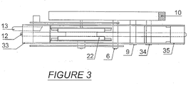
- the safety rope 12 is threaded into the apparatus and is guided by electrical and mechanical components.
- a rope safety device comprises a pair of pulleys 21 and 22 disposed on a support plate 1.
- the first pulley 21 is mounted on a first axis 15 integral with the support plate 1.
- the first driving pulley 21 is fixedly mounted by means of a fixing pin 15 on the support plate 1, being rotated by a actuating unit 2,3,4.
- the actuating unit 2,3,4 comprises an electric motor 2 for actuating and controlling the rotation of the first pulley 21 and for setting the rope in motion.
- the safety device further comprises a transport means 7,30,31 for guiding and ensuring the movement of the rope 12.
- the conveying means 7,30,31 comprises a first pivoting arm 30 pivoting on a hinge pin 6 secured to the support plate 1, and a second pulley 22 mounted on the first pivoting arm 30.
- the second pulley 22 is secured to the first movable pivot arm 30, pivotable about an axis 6.
- the pulley 21 comprises a peripheral winding groove of the rope 12 adapted to receive the second pulley 22 and tighten the rope 12 held under pressure between the first pulley 21 and the second pulley 22 by a spring 7 traction.
- a locking means 9,31 comprises a second pivoting arm 31 cooperating with a locking element 9 integral with the support plate 1 to cause the locking of the rope 12 .
- the locking element 9 is fixedly mounted by means of a fixing pin on the support plate 1
- the second pivoting arm 31 allows a tilting movement between a closed position in which the rope 12 wedged under pressure between the first pulley 21 and the second pulley 22 is set in motion by activation of the electric motor 2, and an open position in which the rope 12 is blocked by the locking means 9.31 and the electric motor 2 is deactivated so that the movement of the rope 12 is stopped.
- the two pivoting arms 30, 31 movably fixed pivot on the main axis 6 and operate independently of one another.
- the motor 2 is adapted to rotate at a substantially constant speed for climbing at a normal pace.
- the electric motor 2 rotates the pulley 21 at a substantially constant speed to keep the rope tensioned during a normal climbing pace so that the safety rope 12 remains taut and climbing is secured.
- the first pulley 21 is formed into a cylinder having an outer surface intended to cooperate with the second pulley 22 shaped as a cylinder, following the pivoting movement of the first pivoting arm 30 towards the closed position, the passage from the closed position to the open blocking position occurring when the tension of the rope 12 exceeds a predetermined threshold causing the tilting movement of the first pivot arm 30.
- a tensioning or biasing spring 7 urging the first pivoting arm 30 in the unlocking direction towards the closed position is provided.
- the threshold of tension or jamming of the rope 12 between the first pulley 21 and the second pulley 22 depends on the restoring force of the tension spring 7.
- the tension of the spring 7 can be adjusted or adjusted by means of a adjustment element 8.
- the rope 12 to be stretched is placed so as to be trapped and rest against the contact surface of the first and second pulleys 21 and 22 of the device.
- the rotation of the pulleys 21 and 22 can then be controlled by the motor 2.
- the tensioning device is normally used for winding the rope 12 during the jamming of the rope 12 between the first pulley 21 and the second pulley 22 due to the tensile force of the spring 7.
- the locking pin 9 may be formed of a locking pin 9 integral with the support plate 1.
- the positioning of the locking pin 9 is such that the rope 12 comes into engagement by wedging between this locking pin 9 and a blocking pulley 34 integral with the second pivoting arm 31 in the open position, so as to ensure a blocking sure.
- This blocking occurs when the value of the tension exerted on the rope 12 is greater than a predetermined threshold and the second pivot arm 31 has made the tilting movement from the closed position.
- the tilting movement of the second pivot arm 31 towards the locking position occurs during a fall of the user when the tension of the rope 12 exceeds the adjustment threshold of the apparatus.
- the tilting of the second pivot arm 31 pivots the locking pulley 34 about the axis 6, from a closed position to a locking position.
- the second pivoting arm 31 is articulated on the plate 1 in an axis 6 and is located opposite the first pivoting arm 30 which cooperates with the return spring 7 to urge the pulley 22 towards the closed position in which the axes 6,16, 33,34,36 are in horizontal alignment.
- a switch mechanism 10 for activating or deactivating the electric motor 2. Following the switching of the second pivot arm 31 down, the switch mechanism 10 is disabled to trigger the stopping of the electric motor 2, and the safety rope 12 is no longer transported. Following the tilting of the second pivot arm 31 upwards in the closed (horizontal) position when the user resumes the climb, the switch mechanism 10 is reactivated so that the electric motor 2 restarts and the safety rope 12 is again switched on.
- an alarm system is provided in the event of system failure. More particularly, a sound module can be provided to control the tension of the rope and prevent the climber in case of failure of the mechanism, for example during a power failure or an unexpected engine stop.
- the safety rope 12 has been introduced into the system as described above.
- the pulley 30, propelled by the engine 2 maintains the safety rope 12 which is between the pulley 30 and the pulley 31 under tension.
- the tension on the safety rope 12 increases (the motor 2 continues to operate) and the rail 31 leaves the closed position (horizontal) to the open position.
- the micro switch 10 is deactivated and the electric motor 2 stops, and the safety rope 12 is no longer transported. If the rise of the user starts again, the safety rope 12 expands and the spring 7 puts the rail 31 in the closed position (horizontal).
- the micro switch 10 is again activated so that the electric motor 2 restarts and the safety rope 12 is again powered.
- the same mechanism is put in place but the body weight of the climber makes the safety rope 12 remains blocked between the pulley 34 and the locking pin 9 which prevents the fall of the climber.
- the tension of the safety rope 12 increases and the same mechanism as described above for a pause of the user takes place. If the climber has stabilized and wants to continue the climb, the same mechanism is set up as described after a break. For the descent of the user the climber must unlock the lock of the safety rope 12. It must pull on the return rope 13.
- the safety rope 12 is held in a state of tension during the climbing of the escalator by the electric motor 2 which propels the drive wheels 21 and 22 via a belt 3 and a driving spiral 4.
- the transport rail 30 is held in the mounted position by a spring 7. If the climbing is interrupted the rope 12 is energized and following this voltage a switch 10 is activated which causes the stopping of the electric motor 2 and driving wheels 21 and 22. During a fall the same mechanism takes place but in addition the weight of the user triggers the security mechanism ie. the rope 12 remains locked between the transport rail 30 and the locking bolt 9 following the inclination of the transport rail 30 down towards the locking bolt 9.
- the spring 7 comes into action and puts the transport rail 30 in the up position, this activates the switch 10 and restarts the motor 2 and the driving wheels 21 and 22.
- the climber causes the first the blocking of the system as described above. Then it puts a slight tension on the return rope 13 which triggers a lifting of the transport rail 30 and removes the pressure on the locking bolt 9 and releases the rope 12.
Landscapes
- Health & Medical Sciences (AREA)
- General Health & Medical Sciences (AREA)
- Business, Economics & Management (AREA)
- Emergency Management (AREA)
- Physical Education & Sports Medicine (AREA)
- Emergency Lowering Means (AREA)
Claims (10)
- Selbstblockierende Sicherheitsvorrichtung für Seil (12), umfassend:- eine Trägerplatte (1),- eine erste Rolle (21), die auf einer ersten Achse (15) montiert ist, die mit der Trägerplatte (1) fest verbunden ist,- ein Transportmittel (7, 30, 31), um die Bewegung des Seils (12) zu führen und zu sichern, wobei das Transportmittel (7, 30, 31) einen ersten Schwenkarm (30) aufweist, der auf einer zweiten Gelenkachse (6) schwenkt, die mit der Trägerplatte (1) fest verbunden ist, und eine zweiten Rolle (22), die auf dem ersten Schwenkarm (30) angebracht ist,- ein Blockiermittel (9, 31), um die Blockierung des Seils (12) zu sichern, und- eine Betätigungseinheit (2, 3, 4), die einen Elektromotor (2) aufweist, um die Rotation der ersten Rolle (21) zu betätigen und zu steuern und um das Seil in Bewegung zu versetzen,dadurch gekennzeichnet, dass das Blockiermittel (9, 31) einen zweiten Schwenkarm (31) aufweist, der mit einem Blockierelement (9) zusammenwirkt, das mit der Trägerplatte (1) fest verbunden ist, um das Seil (12) zu blockieren,
wobei der zweite Schwenkarm (31) eine Kippbewegung zwischen einer geschlossenen Stellung, in welcher das unter Druck zwischen der ersten Rolle (21) und der zweiten Rolle (22) eingeklemmte Seil (12) durch Aktivierung des Elektromotors (2) in Bewegung versetzt wird, und einer offenen Stellung, in welcher das Seil (12) von dem Blockiermittel (9, 31) blockiert ist und der Elektromotor (2) deaktiviert ist, so dass die Bewegung des Seils (12) gestoppt ist, erlaubt. - Vorrichtung nach Anspruch 1, dadurch gekennzeichnet, dass eine Zugfeder (7) den ersten Schwenkarm (30) in die Löserichtung in Richtung der geschlossenen Stellung beansprucht, und dass die Rückholkraft der Zugfeder (7) den Spannungs- oder Klemmgrenzwert des Seils (12) zwischen der ersten Rolle (21) und der zweiten Rolle (22) bestimmt.
- Vorrichtung nach Anspruch 1 oder 2, dadurch gekennzeichnet, dass das Blockiermittel (9, 31) eine Blockierachse (9) aufweist, die von einem Blockierbolzen (9) gebildet ist, der mit der Trägerplatte (1) fest verbunden ist.
- Vorrichtung nach einem der vorangehenden Ansprüche, dadurch gekennzeichnet, dass die Blockierachse (9) auf der Trägerplatte (1) derart positioniert ist, dass das Seil (12) zwischen der Blockierachse (9) und einer Blockierrolle (34) eingeklemmt wird, die mit dem zweiten Schwenkarm (31) in der offenen Stellung fest verbunden ist.
- Vorrichtung nach einem der vorangehenden Ansprüche, dadurch gekennzeichnet, dass die zwei beweglich befestigten Schwenkarme (30, 31) unabhängig voneinander auf der Hauptgelenkachse (6) schwenken.
- Vorrichtung nach einem der vorangehenden Ansprüche, dadurch gekennzeichnet, dass der Motor (2) ausgebildet ist, um in einer substantiell konstanten Geschwindigkeit zu drehen, um das Seil bei einem normal schnellen Klettern unter Spannung zu halten.
- Vorrichtung nach einem der vorangehenden Ansprüche, dadurch gekennzeichnet, dass ein Unterbrechungsmechanismus (10) vorgesehen ist, um den Elektromotor (2) zu aktivieren oder zu deaktivieren, wobei der Unterbrechungsmechanismus (10) deaktiviert wird, um den Elektromotor (2) infolge des Schwenkens des zweiten Schwenkarms (31) in die offene Stellung anzuhalten, wobei der Unterbrechungsmechanismus (10) reaktiviert wird, damit der Elektromotor (2) erneut startet und sich das Sicherheitsseil (12) infolge des Schwenkens des zweiten Schwenkarms (31) in die geschlossene Stellung erneut unter Spannung befindet.
- Vorrichtung nach einem der vorangehenden Ansprüche, dadurch gekennzeichnet, dass die erste Rolle (21) als Zylinder mit einer äußeren Oberfläche ausgebildet ist, die zum Zusammenwirken mit der zweiten Rolle (22) bestimmt ist, die als Zylinder ausgebildet ist.
- Vorrichtung nach einem der vorangehenden Ansprüche, dadurch gekennzeichnet, dass die Betätigungseinheit (2, 3, 4), die den Elektromotor (2) aufweist, eine Antriebsspirale (4) über einen Riemen (3) antreibt, und dass die Antriebsspirale (4) ein Zahnrad (5) in Drehung versetzt, das mit der ersten Antriebsrolle (21) zusammenwirkt, um das Seil (12) in Bewegung zu versetzen.
- Vorrichtung nach einem der vorangehenden Ansprüche, dadurch gekennzeichnet, dass ein Alarmmodul vorgesehen ist, um den Kletterer bei einer Panne der Vorrichtung bei einem Stromausfall oder einem unvorhergesehenen Stopp des Motors (2) zu benachrichtigen.
Applications Claiming Priority (1)
| Application Number | Priority Date | Filing Date | Title |
|---|---|---|---|
| LU92819A LU92819B1 (fr) | 2015-09-08 | 2015-09-08 | Dispositif de sécurité autobloquant pour corde d'escalade |
Publications (2)
| Publication Number | Publication Date |
|---|---|
| EP3141285A1 EP3141285A1 (de) | 2017-03-15 |
| EP3141285B1 true EP3141285B1 (de) | 2018-10-17 |
Family
ID=54256803
Family Applications (1)
| Application Number | Title | Priority Date | Filing Date |
|---|---|---|---|
| EP16185276.9A Not-in-force EP3141285B1 (de) | 2015-09-08 | 2016-08-23 | Selbstblockierende sicherheitsvorrichtung für kletterseil |
Country Status (2)
| Country | Link |
|---|---|
| EP (1) | EP3141285B1 (de) |
| LU (1) | LU92819B1 (de) |
Families Citing this family (6)
| Publication number | Priority date | Publication date | Assignee | Title |
|---|---|---|---|---|
| CN108785904B (zh) * | 2018-05-08 | 2020-10-02 | 山东深川变频科技股份有限公司 | 一种基于伺服电机驱动的下降器 |
| CN111119534B (zh) * | 2020-01-10 | 2025-02-28 | 张家口创鑫机械科技有限公司 | 一种自爬升立体停车位 |
| CN111375154B (zh) * | 2020-04-17 | 2024-05-31 | 福建省特种设备检验研究院 | 一种塔机攀爬安全带吊挂装置及其使用方法 |
| CN111408096B (zh) * | 2020-05-06 | 2021-05-11 | 盐城工学院 | 一种组合型体育体能拓展训练装置 |
| CN113509693B (zh) * | 2021-05-19 | 2025-05-06 | 支点高空(深圳)科技有限公司 | 一种爬绳器 |
| CN114669032B (zh) * | 2022-04-11 | 2023-03-31 | 山东体育学院 | 攀登保护动作训练器 |
Family Cites Families (5)
| Publication number | Priority date | Publication date | Assignee | Title |
|---|---|---|---|---|
| FR2644702B1 (fr) * | 1989-03-22 | 1991-07-12 | Motte Denis | Dispositif pour assurer automatiquement un grimpeur escaladant une paroi |
| FR2727026B1 (fr) * | 1994-11-18 | 1996-12-27 | Jomard Christine Brouty | Dispositif d'assurance automatique d'un grimpeur en cours d'escalade |
| GB0507806D0 (en) * | 2005-04-19 | 2005-05-25 | Bm Engineering Uk Ltd | Belay device |
| FR2950536B1 (fr) | 2009-09-25 | 2011-10-07 | Zedel | Dispositif d'assurance autobloquant pour corde |
| CN103332634A (zh) * | 2013-06-17 | 2013-10-02 | 浙江理工大学 | 一种攀岩辅助装置及方法 |
-
2015
- 2015-09-08 LU LU92819A patent/LU92819B1/fr active IP Right Grant
-
2016
- 2016-08-23 EP EP16185276.9A patent/EP3141285B1/de not_active Not-in-force
Non-Patent Citations (1)
| Title |
|---|
| None * |
Also Published As
| Publication number | Publication date |
|---|---|
| LU92819B1 (fr) | 2017-03-20 |
| EP3141285A1 (de) | 2017-03-15 |
Similar Documents
| Publication | Publication Date | Title |
|---|---|---|
| EP3141285B1 (de) | Selbstblockierende sicherheitsvorrichtung für kletterseil | |
| EP2301631B1 (de) | Selbstblockierende Sicherheitsvorrichtung für ein Seil | |
| EP2754466B1 (de) | Sicherheitssystem zur Fallsicherung mit Blockierfunktion am Seil | |
| EP1834672B1 (de) | Mehrfunktionsgerät zur Sicherung eines Seils | |
| EP1380320B1 (de) | Absturzgesichertes Führungsgerät für eine feste Leine | |
| EP0593369B1 (de) | Sicherheitsabseilvorrichtung | |
| EP2127941B1 (de) | Stoßdämpfungsvorrichtung und mit dieser Vorrichtung ausgestatteter Sitz | |
| EP3056248B1 (de) | Sicherungs- und abseilgerät über ein seil mit übersetzung und anti-panik-blockade | |
| FR3000899A1 (fr) | Appareil de securite antichute et blocage sur corde | |
| FR2547738A1 (fr) | Dispositif de securite pour proteger contre les chutes les personnes travaillant dans un endroit eleve | |
| FR2471199A1 (fr) | Dispositif d'arret d'un ruban de ceinture, notamment de ceinture de securite pour les vehicules | |
| FR2556704A1 (fr) | Limiteur de vitesse pour ascenseurs equipes d'un dispositif d'arret de securite | |
| EP3124081B1 (de) | Vorrichtung zur sicherung am seil für den einsatz als sicherung und als toprope | |
| WO2017072436A1 (fr) | Dispositif antichute a rappel automatique et procédé de fonctionnement afférent | |
| FR2922200A1 (fr) | Systeme de poulie a descente de charge freinee | |
| WO2006035138A1 (fr) | Dispositif assureur descendeur autobloquant pour cordes de tout diametre | |
| WO2011135204A1 (fr) | Dispositif de securite pour grimpeur securise par une corde | |
| FR3100805A1 (fr) | Nacelle, notamment nacelle élévatrice | |
| FR2478471A1 (fr) | Dispositif enrouleur-derouleur d'une sangle, en particulier d'une ceinture de securite | |
| FR2904564A1 (fr) | Appareil assureur et descendeur pour corde | |
| FR3057170A1 (fr) | Dispositif antichute a frein d'enroulement | |
| EP0427657A1 (de) | Einrichtung zur Neutralisierung der Rückzugskraft eines Sicherheitsgurtes mit automatischem Gurtaufroller | |
| WO2003037708A1 (fr) | Systeme de crochet largable | |
| FR2903318A1 (fr) | Appareil antichute double installe sur un anneau de corde. | |
| EP2067503A1 (de) | Einroller mit begrenzter Abrollung |
Legal Events
| Date | Code | Title | Description |
|---|---|---|---|
| PUAI | Public reference made under article 153(3) epc to a published international application that has entered the european phase |
Free format text: ORIGINAL CODE: 0009012 |
|
| STAA | Information on the status of an ep patent application or granted ep patent |
Free format text: STATUS: REQUEST FOR EXAMINATION WAS MADE |
|
| 17P | Request for examination filed |
Effective date: 20160823 |
|
| AK | Designated contracting states |
Kind code of ref document: A1 Designated state(s): AL AT BE BG CH CY CZ DE DK EE ES FI FR GB GR HR HU IE IS IT LI LT LU LV MC MK MT NL NO PL PT RO RS SE SI SK SM TR |
|
| AX | Request for extension of the european patent |
Extension state: BA ME |
|
| GRAP | Despatch of communication of intention to grant a patent |
Free format text: ORIGINAL CODE: EPIDOSNIGR1 |
|
| STAA | Information on the status of an ep patent application or granted ep patent |
Free format text: STATUS: GRANT OF PATENT IS INTENDED |
|
| INTG | Intention to grant announced |
Effective date: 20180605 |
|
| GRAS | Grant fee paid |
Free format text: ORIGINAL CODE: EPIDOSNIGR3 |
|
| GRAA | (expected) grant |
Free format text: ORIGINAL CODE: 0009210 |
|
| STAA | Information on the status of an ep patent application or granted ep patent |
Free format text: STATUS: THE PATENT HAS BEEN GRANTED |
|
| AK | Designated contracting states |
Kind code of ref document: B1 Designated state(s): AL AT BE BG CH CY CZ DE DK EE ES FI FR GB GR HR HU IE IS IT LI LT LU LV MC MK MT NL NO PL PT RO RS SE SI SK SM TR |
|
| REG | Reference to a national code |
Ref country code: GB Ref legal event code: FG4D Free format text: NOT ENGLISH |
|
| REG | Reference to a national code |
Ref country code: CH Ref legal event code: EP |
|
| REG | Reference to a national code |
Ref country code: IE Ref legal event code: FG4D Free format text: LANGUAGE OF EP DOCUMENT: FRENCH |
|
| REG | Reference to a national code |
Ref country code: DE Ref legal event code: R096 Ref document number: 602016006481 Country of ref document: DE Ref country code: AT Ref legal event code: REF Ref document number: 1053303 Country of ref document: AT Kind code of ref document: T Effective date: 20181115 |
|
| REG | Reference to a national code |
Ref country code: NL Ref legal event code: MP Effective date: 20181017 |
|
| REG | Reference to a national code |
Ref country code: LT Ref legal event code: MG4D |
|
| REG | Reference to a national code |
Ref country code: AT Ref legal event code: MK05 Ref document number: 1053303 Country of ref document: AT Kind code of ref document: T Effective date: 20181017 |
|
| PG25 | Lapsed in a contracting state [announced via postgrant information from national office to epo] |
Ref country code: NL Free format text: LAPSE BECAUSE OF FAILURE TO SUBMIT A TRANSLATION OF THE DESCRIPTION OR TO PAY THE FEE WITHIN THE PRESCRIBED TIME-LIMIT Effective date: 20181017 |
|
| PG25 | Lapsed in a contracting state [announced via postgrant information from national office to epo] |
Ref country code: FI Free format text: LAPSE BECAUSE OF FAILURE TO SUBMIT A TRANSLATION OF THE DESCRIPTION OR TO PAY THE FEE WITHIN THE PRESCRIBED TIME-LIMIT Effective date: 20181017 Ref country code: HR Free format text: LAPSE BECAUSE OF FAILURE TO SUBMIT A TRANSLATION OF THE DESCRIPTION OR TO PAY THE FEE WITHIN THE PRESCRIBED TIME-LIMIT Effective date: 20181017 Ref country code: PL Free format text: LAPSE BECAUSE OF FAILURE TO SUBMIT A TRANSLATION OF THE DESCRIPTION OR TO PAY THE FEE WITHIN THE PRESCRIBED TIME-LIMIT Effective date: 20181017 Ref country code: LV Free format text: LAPSE BECAUSE OF FAILURE TO SUBMIT A TRANSLATION OF THE DESCRIPTION OR TO PAY THE FEE WITHIN THE PRESCRIBED TIME-LIMIT Effective date: 20181017 Ref country code: AT Free format text: LAPSE BECAUSE OF FAILURE TO SUBMIT A TRANSLATION OF THE DESCRIPTION OR TO PAY THE FEE WITHIN THE PRESCRIBED TIME-LIMIT Effective date: 20181017 Ref country code: NO Free format text: LAPSE BECAUSE OF FAILURE TO SUBMIT A TRANSLATION OF THE DESCRIPTION OR TO PAY THE FEE WITHIN THE PRESCRIBED TIME-LIMIT Effective date: 20190117 Ref country code: ES Free format text: LAPSE BECAUSE OF FAILURE TO SUBMIT A TRANSLATION OF THE DESCRIPTION OR TO PAY THE FEE WITHIN THE PRESCRIBED TIME-LIMIT Effective date: 20181017 Ref country code: IS Free format text: LAPSE BECAUSE OF FAILURE TO SUBMIT A TRANSLATION OF THE DESCRIPTION OR TO PAY THE FEE WITHIN THE PRESCRIBED TIME-LIMIT Effective date: 20190217 Ref country code: BG Free format text: LAPSE BECAUSE OF FAILURE TO SUBMIT A TRANSLATION OF THE DESCRIPTION OR TO PAY THE FEE WITHIN THE PRESCRIBED TIME-LIMIT Effective date: 20190117 Ref country code: LT Free format text: LAPSE BECAUSE OF FAILURE TO SUBMIT A TRANSLATION OF THE DESCRIPTION OR TO PAY THE FEE WITHIN THE PRESCRIBED TIME-LIMIT Effective date: 20181017 |
|
| PG25 | Lapsed in a contracting state [announced via postgrant information from national office to epo] |
Ref country code: AL Free format text: LAPSE BECAUSE OF FAILURE TO SUBMIT A TRANSLATION OF THE DESCRIPTION OR TO PAY THE FEE WITHIN THE PRESCRIBED TIME-LIMIT Effective date: 20181017 Ref country code: SE Free format text: LAPSE BECAUSE OF FAILURE TO SUBMIT A TRANSLATION OF THE DESCRIPTION OR TO PAY THE FEE WITHIN THE PRESCRIBED TIME-LIMIT Effective date: 20181017 Ref country code: PT Free format text: LAPSE BECAUSE OF FAILURE TO SUBMIT A TRANSLATION OF THE DESCRIPTION OR TO PAY THE FEE WITHIN THE PRESCRIBED TIME-LIMIT Effective date: 20190217 Ref country code: GR Free format text: LAPSE BECAUSE OF FAILURE TO SUBMIT A TRANSLATION OF THE DESCRIPTION OR TO PAY THE FEE WITHIN THE PRESCRIBED TIME-LIMIT Effective date: 20190118 Ref country code: RS Free format text: LAPSE BECAUSE OF FAILURE TO SUBMIT A TRANSLATION OF THE DESCRIPTION OR TO PAY THE FEE WITHIN THE PRESCRIBED TIME-LIMIT Effective date: 20181017 |
|
| REG | Reference to a national code |
Ref country code: DE Ref legal event code: R097 Ref document number: 602016006481 Country of ref document: DE |
|
| PG25 | Lapsed in a contracting state [announced via postgrant information from national office to epo] |
Ref country code: CZ Free format text: LAPSE BECAUSE OF FAILURE TO SUBMIT A TRANSLATION OF THE DESCRIPTION OR TO PAY THE FEE WITHIN THE PRESCRIBED TIME-LIMIT Effective date: 20181017 Ref country code: IT Free format text: LAPSE BECAUSE OF FAILURE TO SUBMIT A TRANSLATION OF THE DESCRIPTION OR TO PAY THE FEE WITHIN THE PRESCRIBED TIME-LIMIT Effective date: 20181017 Ref country code: DK Free format text: LAPSE BECAUSE OF FAILURE TO SUBMIT A TRANSLATION OF THE DESCRIPTION OR TO PAY THE FEE WITHIN THE PRESCRIBED TIME-LIMIT Effective date: 20181017 |
|
| PLBE | No opposition filed within time limit |
Free format text: ORIGINAL CODE: 0009261 |
|
| STAA | Information on the status of an ep patent application or granted ep patent |
Free format text: STATUS: NO OPPOSITION FILED WITHIN TIME LIMIT |
|
| PG25 | Lapsed in a contracting state [announced via postgrant information from national office to epo] |
Ref country code: SM Free format text: LAPSE BECAUSE OF FAILURE TO SUBMIT A TRANSLATION OF THE DESCRIPTION OR TO PAY THE FEE WITHIN THE PRESCRIBED TIME-LIMIT Effective date: 20181017 Ref country code: EE Free format text: LAPSE BECAUSE OF FAILURE TO SUBMIT A TRANSLATION OF THE DESCRIPTION OR TO PAY THE FEE WITHIN THE PRESCRIBED TIME-LIMIT Effective date: 20181017 Ref country code: SK Free format text: LAPSE BECAUSE OF FAILURE TO SUBMIT A TRANSLATION OF THE DESCRIPTION OR TO PAY THE FEE WITHIN THE PRESCRIBED TIME-LIMIT Effective date: 20181017 Ref country code: RO Free format text: LAPSE BECAUSE OF FAILURE TO SUBMIT A TRANSLATION OF THE DESCRIPTION OR TO PAY THE FEE WITHIN THE PRESCRIBED TIME-LIMIT Effective date: 20181017 |
|
| 26N | No opposition filed |
Effective date: 20190718 |
|
| PG25 | Lapsed in a contracting state [announced via postgrant information from national office to epo] |
Ref country code: SI Free format text: LAPSE BECAUSE OF FAILURE TO SUBMIT A TRANSLATION OF THE DESCRIPTION OR TO PAY THE FEE WITHIN THE PRESCRIBED TIME-LIMIT Effective date: 20181017 |
|
| REG | Reference to a national code |
Ref country code: DE Ref legal event code: R119 Ref document number: 602016006481 Country of ref document: DE |
|
| PG25 | Lapsed in a contracting state [announced via postgrant information from national office to epo] |
Ref country code: TR Free format text: LAPSE BECAUSE OF FAILURE TO SUBMIT A TRANSLATION OF THE DESCRIPTION OR TO PAY THE FEE WITHIN THE PRESCRIBED TIME-LIMIT Effective date: 20181017 |
|
| PG25 | Lapsed in a contracting state [announced via postgrant information from national office to epo] |
Ref country code: CH Free format text: LAPSE BECAUSE OF NON-PAYMENT OF DUE FEES Effective date: 20190831 Ref country code: LU Free format text: LAPSE BECAUSE OF NON-PAYMENT OF DUE FEES Effective date: 20190823 Ref country code: LI Free format text: LAPSE BECAUSE OF NON-PAYMENT OF DUE FEES Effective date: 20190831 Ref country code: MC Free format text: LAPSE BECAUSE OF FAILURE TO SUBMIT A TRANSLATION OF THE DESCRIPTION OR TO PAY THE FEE WITHIN THE PRESCRIBED TIME-LIMIT Effective date: 20181017 |
|
| REG | Reference to a national code |
Ref country code: BE Ref legal event code: MM Effective date: 20190831 |
|
| PG25 | Lapsed in a contracting state [announced via postgrant information from national office to epo] |
Ref country code: DE Free format text: LAPSE BECAUSE OF NON-PAYMENT OF DUE FEES Effective date: 20200303 Ref country code: FR Free format text: LAPSE BECAUSE OF NON-PAYMENT OF DUE FEES Effective date: 20190831 Ref country code: IE Free format text: LAPSE BECAUSE OF NON-PAYMENT OF DUE FEES Effective date: 20190823 |
|
| PG25 | Lapsed in a contracting state [announced via postgrant information from national office to epo] |
Ref country code: BE Free format text: LAPSE BECAUSE OF NON-PAYMENT OF DUE FEES Effective date: 20190831 |
|
| GBPC | Gb: european patent ceased through non-payment of renewal fee |
Effective date: 20200823 |
|
| PG25 | Lapsed in a contracting state [announced via postgrant information from national office to epo] |
Ref country code: CY Free format text: LAPSE BECAUSE OF FAILURE TO SUBMIT A TRANSLATION OF THE DESCRIPTION OR TO PAY THE FEE WITHIN THE PRESCRIBED TIME-LIMIT Effective date: 20181017 |
|
| PG25 | Lapsed in a contracting state [announced via postgrant information from national office to epo] |
Ref country code: MT Free format text: LAPSE BECAUSE OF FAILURE TO SUBMIT A TRANSLATION OF THE DESCRIPTION OR TO PAY THE FEE WITHIN THE PRESCRIBED TIME-LIMIT Effective date: 20181017 Ref country code: HU Free format text: LAPSE BECAUSE OF FAILURE TO SUBMIT A TRANSLATION OF THE DESCRIPTION OR TO PAY THE FEE WITHIN THE PRESCRIBED TIME-LIMIT; INVALID AB INITIO Effective date: 20160823 |
|
| PG25 | Lapsed in a contracting state [announced via postgrant information from national office to epo] |
Ref country code: GB Free format text: LAPSE BECAUSE OF NON-PAYMENT OF DUE FEES Effective date: 20200823 |
|
| PG25 | Lapsed in a contracting state [announced via postgrant information from national office to epo] |
Ref country code: MK Free format text: LAPSE BECAUSE OF FAILURE TO SUBMIT A TRANSLATION OF THE DESCRIPTION OR TO PAY THE FEE WITHIN THE PRESCRIBED TIME-LIMIT Effective date: 20181017 |