EP1835580A1 - Armoire de distribution de câbles ayant des moyens pour empêcher sa rupture - Google Patents
Armoire de distribution de câbles ayant des moyens pour empêcher sa rupture Download PDFInfo
- Publication number
- EP1835580A1 EP1835580A1 EP06005053A EP06005053A EP1835580A1 EP 1835580 A1 EP1835580 A1 EP 1835580A1 EP 06005053 A EP06005053 A EP 06005053A EP 06005053 A EP06005053 A EP 06005053A EP 1835580 A1 EP1835580 A1 EP 1835580A1
- Authority
- EP
- European Patent Office
- Prior art keywords
- door
- wall
- cabinet
- cabinet according
- protection
- Prior art date
- Legal status (The legal status is an assumption and is not a legal conclusion. Google has not performed a legal analysis and makes no representation as to the accuracy of the status listed.)
- Granted
Links
Images
Classifications
-
- H—ELECTRICITY
- H02—GENERATION; CONVERSION OR DISTRIBUTION OF ELECTRIC POWER
- H02B—BOARDS, SUBSTATIONS OR SWITCHING ARRANGEMENTS FOR THE SUPPLY OR DISTRIBUTION OF ELECTRIC POWER
- H02B1/00—Frameworks, boards, panels, desks, casings; Details of substations or switching arrangements
- H02B1/26—Casings; Parts thereof or accessories therefor
- H02B1/50—Pedestal- or pad-mounted casings; Parts thereof or accessories therefor
-
- H—ELECTRICITY
- H02—GENERATION; CONVERSION OR DISTRIBUTION OF ELECTRIC POWER
- H02B—BOARDS, SUBSTATIONS OR SWITCHING ARRANGEMENTS FOR THE SUPPLY OR DISTRIBUTION OF ELECTRIC POWER
- H02B1/00—Frameworks, boards, panels, desks, casings; Details of substations or switching arrangements
- H02B1/26—Casings; Parts thereof or accessories therefor
- H02B1/28—Casings; Parts thereof or accessories therefor dustproof, splashproof, drip-proof, waterproof or flameproof
Definitions
- the invention relates to a cable distribution cabinet with at least one lockable door, which is pivotally mounted in the housing of the cabinet.
- Cable distribution cabinets for use in the power supply especially cable distribution cabinets for low voltages, are well known in the art.
- the distribution cabinets are usually installed outdoors and are preferably suitable for installation of distribution components for the public power supply and equipment components, such as traffic systems, pump controls, etc ..
- Known cable distribution cabinets consist for example of plastic. Schrankober- / bottom part form a unit and are bolted or connected by a bolt-free locking slide with integrated breaking point.
- the cabinet consists of individual parts, which are in particular assembled in a modular system.
- the door lock is done for example by a three-point lock, suitable for the installation of commercially available semi-profile cylinder.
- the short-circuit power in electrical networks and systems has increased sharply over the last few years. This also increases the power that z. B. is converted by heat in heat. This released heat energy as a result of short-circuit arcs can break cable distribution cabinets by pressure increase; the thermal expansion of the trapped air leads to an overpressure that can not be dissipated quickly enough by the existing vents. Furthermore, an additional pressure increase can take place by thermal decomposition of insulating materials, by increasing the volume or by forming explosive mixtures.
- Object of the present invention is to develop a cable distribution cabinet of the type mentioned so that it is burst-proof in a short circuit arc fault.
- a cable distribution cabinet with at least one lockable door, which is pivotally mounted in the housing of the cabinet, wherein the cabinet is provided in the region of the connection of door and wall with a rupture protection, which is designed as a band or rope connecting the wall to the door, wherein the rupture fuse adjacent to the pivot axis of the door at this and the wall engages.
- the bursting protection is designed as a band. This can be due to its width very easy to assemble and allows different arrangements in the cabinet. It is particularly expedient if the band is arranged in the manner of a loop, wherein the superimposed free ends of the band are connected to the wall or the door, in particular by means of a screw connection, and the loop end by means of a plug connection, in particular one without auxiliary tool producible and detachable plug-in connection, is mounted in the door or the wall.
- the formation of the band in the manner of a loop allows a relatively large power consumption of the band and also allows easy installation and easy replacement of the door.
- the bursting protection in particular the band, is elastic.
- the bursting protection of plastic, rubber or rubber with insert has such a length that after the bursting operation and reducing the overpressure in the cabinet, the door and wall are moved away from each other in the area of the rupture protection device by less than 50 mm, preferably less than 35 mm.
- the advantage of the elastic design of the rupture protection is to be seen in particular in that energy is taken up by the rupture protection when applying the cable distribution cabinet with overpressure in the event of bursting, so that the wall and door side bearings of the rupture are claimed less. Furthermore, as a result of their elastic compliance, the rupture protection can stretch more, so that the high pressure in the interior of the cabinet can be reduced by a larger gap between the door and the wall. It can be accepted that this gap has a maximum opening of> 50 mm. Due to the elasticity of the bursting protection, the gap, as soon as the pressure inside the cable distribution cabinet decreases, degraded and then, with complete reduction of the pressure in the cabinet, the door and the wall moved a maximum of 50 mm away from each other.
- the maximum gap can be, for example, a maximum of 12 mm due to a shorter elastic band or rope, which corresponds to finger safety, so that the stricter protection class IP 2X according to EN 60529 is maintained.
- This protection class is based on a tester with a diameter of 12 mm, in contrast to the protection class IP 1X with a test ball diameter of 50 mm, which corresponds to hand back safety.
- the cabinet is particularly designed so that the door is mounted in opposite end portions, along a boundary edge of the door in the housing, be it in the roof, a lower segment or the wall of the housing.
- the rupture protection is arranged in particular between the bearing point of the door, preferably in the region of the middle third between the bearing points of the door, in particular at half the length between the bearing points.
- the door adjacent to the rupture protection, is provided with at least one molded part, which is parallel to the plane of the door effective and engages behind a molded part of the wall in the closed position of the door.
- This arrangement has the task to prevent Wandalismus by a leverage of the cabinet is much more difficult in this area.
- a resilient bursting these can when dismantling the high pressure in the interior of the cabinet, and thus the Zugurwölben wall and door, the wall and the door to move back to each other so that the moldings are transferred back into their rear grip position and thus the Normally open and close the door.
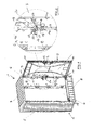
- the cable distribution cabinet illustrated in Figure 1 is illustrated without a pedestal buried in the ground. Also not shown are distributor components to be installed in the cabinet and device components.
- the cabinet 1 has a housing 2 and a pivotally mounted in this door 3.
- the housing 2 has a rear wall 4, a left side wall 5, a right side wall 6, a roof 7 and a front segment 8, which is arranged below the door 3 on.
- the cabinet is made of plastic and he turns, based on the closed position of the door 3, essentially as a cuboid object.
- the door 3 is rectangular. In the region of a longitudinal side 9, it is mounted in the region of its upper end 10 and its lower end 11 in a known manner via not shown pins in recesses of the roof 7 and the segment 8. Since the cabinet 1 is formed overall as a plug-in system, the door 3 can be easily mounted by being inserted with its lower pin in the recess of the segment 8, then tilted with its longitudinal side 9 in the vertical position, in which the upper pin the door 3 is aligned with the recess in the roof 7 and then the roof and the two side walls 5 and 6 are put together.
- the door 3 is provided in the region of the other longitudinal side 12 with a closing mechanism 13 which cooperates with the upper and lower pins 14 via a linkage, not illustrated. When the door 3 is closed, these pins 14 engage in recesses in the roof 7 and in the segment 8, only the recess 15 in the segment 8 being visible in FIG.
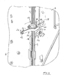
- the right wall 6 and the door 3 are also provided with a safeguard against prying open the door 3 in the middle section between their bearings in the roof 7 and the segment 8. This detail and the bursting fuse to be described in more detail below are shown in an enlarged scale in FIG. 2:
- a hook-shaped molding 16 with the door 3 and a hook-shaped molding 17 is connected to the right side wall 6.
- the molding 16 is parallel to the plane of the door 3, the molding 17 parallel to the plane of the right side wall 6 effective.
- the mold part 16 connected to the door 3 engages behind a molded part of the right side wall 6, which is designed as a web 18. Accordingly engages with the door closed 3 connected to the right side wall 6 molding 17 a connected to the door 3 molding 19.
- a levering of the cabinet in the area between the door 3 and the right side wall 6 much more difficult.
- the bursting 20 is arranged.
- This is designed as an elastic band, specifically designed as an elastic hose.
- the band or the tube is arranged in the manner of a loop, wherein the superimposed free ends of the band 20 are connected to the right side wall 6 by a screw 22 passes through the double-layered tape and is screwed into a sprayed onto the side wall 6 cam 23 ,
- the loop end 24, thus the region of the band which faces away from the screw 22, is mounted in the door 3 by means of a plug connection. This plug-in connection can be made and released without an auxiliary tool.
- the loop end 24 is penetrated by a rod, not shown in the illustration of these figures, wherein a provided with a slot 25 and an open-top receptacle 27 Bearing part is connected to the door 3.
- the double-layered tape 20 passes through the slot 25 and the rod is inserted into the receptacle 27.
- the length of the bursting protection 20 or of the band is dimensioned such that after the bursting operation and reduction of the overpressure in the cabinet 1, the door 3 and the right side wall 6 are moved away from each other in the region of the bursting protection 20 less than 50 mm, preferably less than 35 mm ,
Landscapes
- Engineering & Computer Science (AREA)
- Power Engineering (AREA)
- Patch Boards (AREA)
Priority Applications (2)
| Application Number | Priority Date | Filing Date | Title |
|---|---|---|---|
| EP06005053A EP1835580B1 (fr) | 2006-03-13 | 2006-03-13 | Armoire de distribution de câbles ayant des moyens pour empêcher sa rupture |
| PL06005053T PL1835580T3 (pl) | 2006-03-13 | 2006-03-13 | Szafka rozdzielcza do kabli z zabezpieczeniem przed rozerwaniem |
Applications Claiming Priority (1)
| Application Number | Priority Date | Filing Date | Title |
|---|---|---|---|
| EP06005053A EP1835580B1 (fr) | 2006-03-13 | 2006-03-13 | Armoire de distribution de câbles ayant des moyens pour empêcher sa rupture |
Publications (2)
| Publication Number | Publication Date |
|---|---|
| EP1835580A1 true EP1835580A1 (fr) | 2007-09-19 |
| EP1835580B1 EP1835580B1 (fr) | 2012-09-12 |
Family
ID=36774162
Family Applications (1)
| Application Number | Title | Priority Date | Filing Date |
|---|---|---|---|
| EP06005053A Expired - Lifetime EP1835580B1 (fr) | 2006-03-13 | 2006-03-13 | Armoire de distribution de câbles ayant des moyens pour empêcher sa rupture |
Country Status (2)
| Country | Link |
|---|---|
| EP (1) | EP1835580B1 (fr) |
| PL (1) | PL1835580T3 (fr) |
Cited By (4)
| Publication number | Priority date | Publication date | Assignee | Title |
|---|---|---|---|---|
| CN101783487A (zh) * | 2009-01-15 | 2010-07-21 | 琼·米勒电子技术制造厂有限责任公司 | 具有壳体和在该壳体中支承的门的电缆配电箱 |
| DE102009005141A1 (de) | 2009-01-15 | 2010-07-22 | Jean Müller GmbH Elektrotechnische Fabrik | Kabelverteilerschrank |
| CN111683481A (zh) * | 2020-06-05 | 2020-09-18 | 李豪杰 | 一种通讯机柜 |
| EP3278411B1 (fr) * | 2015-04-03 | 2021-05-26 | Eaton Intelligent Power Limited | Armoire électrique basse tension à risque d'apparition d'arc électrique réduit |
Citations (2)
| Publication number | Priority date | Publication date | Assignee | Title |
|---|---|---|---|---|
| FR1405441A (fr) * | 1964-05-30 | 1965-07-09 | Telemecanique Electrique | Perfectionnements aux coffrets anti-déflagrants |
| DE9101147U1 (de) * | 1991-02-01 | 1991-04-25 | Licentia Patent-Verwaltungs-Gmbh, 6000 Frankfurt | Schaltschrank mit Druckentlastung |
-
2006
- 2006-03-13 PL PL06005053T patent/PL1835580T3/pl unknown
- 2006-03-13 EP EP06005053A patent/EP1835580B1/fr not_active Expired - Lifetime
Patent Citations (2)
| Publication number | Priority date | Publication date | Assignee | Title |
|---|---|---|---|---|
| FR1405441A (fr) * | 1964-05-30 | 1965-07-09 | Telemecanique Electrique | Perfectionnements aux coffrets anti-déflagrants |
| DE9101147U1 (de) * | 1991-02-01 | 1991-04-25 | Licentia Patent-Verwaltungs-Gmbh, 6000 Frankfurt | Schaltschrank mit Druckentlastung |
Cited By (8)
| Publication number | Priority date | Publication date | Assignee | Title |
|---|---|---|---|---|
| CN101783487A (zh) * | 2009-01-15 | 2010-07-21 | 琼·米勒电子技术制造厂有限责任公司 | 具有壳体和在该壳体中支承的门的电缆配电箱 |
| DE102009005140A1 (de) | 2009-01-15 | 2010-07-22 | Jean Müller GmbH Elektrotechnische Fabrik | Kabelverteilerschrank mit Gehäuse und in diesem gelagerter Tür |
| DE102009005141A1 (de) | 2009-01-15 | 2010-07-22 | Jean Müller GmbH Elektrotechnische Fabrik | Kabelverteilerschrank |
| CN101783487B (zh) * | 2009-01-15 | 2014-12-17 | 琼·米勒电子技术制造厂有限责任公司 | 具有壳体和在该壳体中支承的门的电缆配电箱 |
| DE102009005140B4 (de) | 2009-01-15 | 2020-06-25 | Jean Müller GmbH Elektrotechnische Fabrik | Kabelverteilerschrank mit Gehäuse und in diesem gelagerter Tür |
| DE102009005141B4 (de) * | 2009-01-15 | 2020-10-29 | Jean Müller GmbH Elektrotechnische Fabrik | Kabelverteilerschrank |
| EP3278411B1 (fr) * | 2015-04-03 | 2021-05-26 | Eaton Intelligent Power Limited | Armoire électrique basse tension à risque d'apparition d'arc électrique réduit |
| CN111683481A (zh) * | 2020-06-05 | 2020-09-18 | 李豪杰 | 一种通讯机柜 |
Also Published As
| Publication number | Publication date |
|---|---|
| PL1835580T3 (pl) | 2013-03-29 |
| EP1835580B1 (fr) | 2012-09-12 |
Similar Documents
| Publication | Publication Date | Title |
|---|---|---|
| DE102008017423B4 (de) | Überspannungsschutzgerät | |
| DE202008004699U1 (de) | Befestigungsvorrichtung zur Befestigung steckbarer elektrischer Gehäuse | |
| DE202013105328U1 (de) | Türverriegelungsmechanik für die Betätigung der Sperrkulisse eines Trennschalters an einem Schaltschrank sowie eine entsprechende Schaltschrankanordnung | |
| EP3685478A1 (fr) | Connecteur enfichable pourvu d'un étrier de verrouillage avec élément de blocage ainsi que procédé de verrouillage et de déverrouillage d'un connecteur enfichable | |
| WO2005027288A1 (fr) | Obturateur de securite verrouillable pour bati connectable de sectionneurs de puissance basse tension | |
| EP2154701B1 (fr) | Commutateur d'installation doté d'un dispositif de protection | |
| EP1835580B1 (fr) | Armoire de distribution de câbles ayant des moyens pour empêcher sa rupture | |
| DE102004044672A1 (de) | Scharnieraufbau und Schutzvorrichtung mit einem Scharnieraufbau | |
| DE102009005140B4 (de) | Kabelverteilerschrank mit Gehäuse und in diesem gelagerter Tür | |
| DE69523579T2 (de) | Gehäuse für ein elektrisches Gerät | |
| DE10040682C1 (de) | Abfrageeinrichtung für ein in einem Schaltfeld verfahrbares Schaltgerät | |
| DE202008004009U1 (de) | Verteilergehäuse | |
| DE4300212C2 (de) | Druckfestes Gehäuse mit Anschlußkästen und Sicherheitsverriegelung | |
| WO2015071144A1 (fr) | Dispositif de verrouillage d'un bloc électrique mobile | |
| DE102011006112B4 (de) | Elektrischer Schalter und Überstromauslösemodul | |
| DE102007003674B3 (de) | Lagerungseinrichtung zur Aufnahme einer Lagerachse | |
| DE102010012644B4 (de) | Abdeckvorrichtung zum Schutz einer elektrischen Anlage | |
| DE19652131C1 (de) | Elektrischer Verteilerschrank mit einer Druckentlastungseinrichtung | |
| DE102017115730B4 (de) | LED-Panel mit ausschwenkbarem Steckverbinder | |
| EP0885449B1 (fr) | Interrupteur de puissance avec support de levier de contact isolant | |
| DE19545632C2 (de) | Schlüsselschalter | |
| DE10153709A1 (de) | Kabelkanalübergang zwischen einem Türflügel und einer Türzarge | |
| EP2806443B1 (fr) | Dispositif de commutation rotatif pour un appareil de commutation | |
| EP2637270B1 (fr) | Cadre amovible pour un appareil de commutation électrique enfichable, notamment un disjoncteur enfichable | |
| EP2808599B1 (fr) | Éclairage de chantier |
Legal Events
| Date | Code | Title | Description |
|---|---|---|---|
| PUAI | Public reference made under article 153(3) epc to a published international application that has entered the european phase |
Free format text: ORIGINAL CODE: 0009012 |
|
| 17P | Request for examination filed |
Effective date: 20070221 |
|
| AK | Designated contracting states |
Kind code of ref document: A1 Designated state(s): AT BE BG CH CY CZ DE DK EE ES FI FR GB GR HU IE IS IT LI LT LU LV MC NL PL PT RO SE SI SK TR |
|
| AX | Request for extension of the european patent |
Extension state: AL BA HR MK YU |
|
| AKX | Designation fees paid |
Designated state(s): AT DE PL |
|
| GRAP | Despatch of communication of intention to grant a patent |
Free format text: ORIGINAL CODE: EPIDOSNIGR1 |
|
| GRAS | Grant fee paid |
Free format text: ORIGINAL CODE: EPIDOSNIGR3 |
|
| GRAA | (expected) grant |
Free format text: ORIGINAL CODE: 0009210 |
|
| AK | Designated contracting states |
Kind code of ref document: B1 Designated state(s): AT DE PL |
|
| REG | Reference to a national code |
Ref country code: AT Ref legal event code: REF Ref document number: 575429 Country of ref document: AT Kind code of ref document: T Effective date: 20120915 |
|
| REG | Reference to a national code |
Ref country code: DE Ref legal event code: R096 Ref document number: 502006011955 Country of ref document: DE Effective date: 20121108 |
|
| REG | Reference to a national code |
Ref country code: PL Ref legal event code: T3 |
|
| PLBE | No opposition filed within time limit |
Free format text: ORIGINAL CODE: 0009261 |
|
| STAA | Information on the status of an ep patent application or granted ep patent |
Free format text: STATUS: NO OPPOSITION FILED WITHIN TIME LIMIT |
|
| 26N | No opposition filed |
Effective date: 20130613 |
|
| REG | Reference to a national code |
Ref country code: DE Ref legal event code: R097 Ref document number: 502006011955 Country of ref document: DE Effective date: 20130613 |
|
| P01 | Opt-out of the competence of the unified patent court (upc) registered |
Effective date: 20230519 |
|
| PGFP | Annual fee paid to national office [announced via postgrant information from national office to epo] |
Ref country code: DE Payment date: 20250324 Year of fee payment: 20 |
|
| PGFP | Annual fee paid to national office [announced via postgrant information from national office to epo] |
Ref country code: AT Payment date: 20250320 Year of fee payment: 20 |
|
| PGFP | Annual fee paid to national office [announced via postgrant information from national office to epo] |
Ref country code: PL Payment date: 20250303 Year of fee payment: 20 |
|
| REG | Reference to a national code |
Ref country code: DE Ref legal event code: R071 Ref document number: 502006011955 Country of ref document: DE |