EP1838371B1 - Abgabevorrichtung - Google Patents
Abgabevorrichtung Download PDFInfo
- Publication number
- EP1838371B1 EP1838371B1 EP06703451.2A EP06703451A EP1838371B1 EP 1838371 B1 EP1838371 B1 EP 1838371B1 EP 06703451 A EP06703451 A EP 06703451A EP 1838371 B1 EP1838371 B1 EP 1838371B1
- Authority
- EP
- European Patent Office
- Prior art keywords
- dispenser
- container
- housing
- dispenser housing
- track
- Prior art date
- Legal status (The legal status is an assumption and is not a legal conclusion. Google has not performed a legal analysis and makes no representation as to the accuracy of the status listed.)
- Expired - Lifetime
Links
Images




Classifications
-
- A—HUMAN NECESSITIES
- A61—MEDICAL OR VETERINARY SCIENCE; HYGIENE
- A61M—DEVICES FOR INTRODUCING MEDIA INTO, OR ONTO, THE BODY; DEVICES FOR TRANSDUCING BODY MEDIA OR FOR TAKING MEDIA FROM THE BODY; DEVICES FOR PRODUCING OR ENDING SLEEP OR STUPOR
- A61M15/00—Inhalators
- A61M15/009—Inhalators using medicine packages with incorporated spraying means, e.g. aerosol cans
-
- A—HUMAN NECESSITIES
- A61—MEDICAL OR VETERINARY SCIENCE; HYGIENE
- A61M—DEVICES FOR INTRODUCING MEDIA INTO, OR ONTO, THE BODY; DEVICES FOR TRANSDUCING BODY MEDIA OR FOR TAKING MEDIA FROM THE BODY; DEVICES FOR PRODUCING OR ENDING SLEEP OR STUPOR
- A61M15/00—Inhalators
- A61M15/0065—Inhalators with dosage or measuring devices
- A61M15/0068—Indicating or counting the number of dispensed doses or of remaining doses
- A61M15/007—Mechanical counters
- A61M15/0071—Mechanical counters having a display or indicator
- A61M15/0073—Mechanical counters having a display or indicator on a ring
-
- A—HUMAN NECESSITIES
- A61—MEDICAL OR VETERINARY SCIENCE; HYGIENE
- A61M—DEVICES FOR INTRODUCING MEDIA INTO, OR ONTO, THE BODY; DEVICES FOR TRANSDUCING BODY MEDIA OR FOR TAKING MEDIA FROM THE BODY; DEVICES FOR PRODUCING OR ENDING SLEEP OR STUPOR
- A61M11/00—Sprayers or atomisers specially adapted for therapeutic purposes
- A61M11/06—Sprayers or atomisers specially adapted for therapeutic purposes of the injector type
- A61M11/08—Pocket atomisers of the injector type
-
- A—HUMAN NECESSITIES
- A61—MEDICAL OR VETERINARY SCIENCE; HYGIENE
- A61M—DEVICES FOR INTRODUCING MEDIA INTO, OR ONTO, THE BODY; DEVICES FOR TRANSDUCING BODY MEDIA OR FOR TAKING MEDIA FROM THE BODY; DEVICES FOR PRODUCING OR ENDING SLEEP OR STUPOR
- A61M15/00—Inhalators
- A61M15/0001—Details of inhalators; Constructional features thereof
- A61M15/0021—Mouthpieces therefor
-
- A—HUMAN NECESSITIES
- A61—MEDICAL OR VETERINARY SCIENCE; HYGIENE
- A61M—DEVICES FOR INTRODUCING MEDIA INTO, OR ONTO, THE BODY; DEVICES FOR TRANSDUCING BODY MEDIA OR FOR TAKING MEDIA FROM THE BODY; DEVICES FOR PRODUCING OR ENDING SLEEP OR STUPOR
- A61M15/00—Inhalators
- A61M15/0001—Details of inhalators; Constructional features thereof
- A61M15/0021—Mouthpieces therefor
- A61M15/0025—Mouthpieces therefor with caps
-
- A—HUMAN NECESSITIES
- A61—MEDICAL OR VETERINARY SCIENCE; HYGIENE
- A61M—DEVICES FOR INTRODUCING MEDIA INTO, OR ONTO, THE BODY; DEVICES FOR TRANSDUCING BODY MEDIA OR FOR TAKING MEDIA FROM THE BODY; DEVICES FOR PRODUCING OR ENDING SLEEP OR STUPOR
- A61M15/00—Inhalators
- A61M15/0065—Inhalators with dosage or measuring devices
-
- A—HUMAN NECESSITIES
- A61—MEDICAL OR VETERINARY SCIENCE; HYGIENE
- A61M—DEVICES FOR INTRODUCING MEDIA INTO, OR ONTO, THE BODY; DEVICES FOR TRANSDUCING BODY MEDIA OR FOR TAKING MEDIA FROM THE BODY; DEVICES FOR PRODUCING OR ENDING SLEEP OR STUPOR
- A61M15/00—Inhalators
- A61M15/0065—Inhalators with dosage or measuring devices
- A61M15/0068—Indicating or counting the number of dispensed doses or of remaining doses
-
- A—HUMAN NECESSITIES
- A61—MEDICAL OR VETERINARY SCIENCE; HYGIENE
- A61M—DEVICES FOR INTRODUCING MEDIA INTO, OR ONTO, THE BODY; DEVICES FOR TRANSDUCING BODY MEDIA OR FOR TAKING MEDIA FROM THE BODY; DEVICES FOR PRODUCING OR ENDING SLEEP OR STUPOR
- A61M15/00—Inhalators
- A61M15/0065—Inhalators with dosage or measuring devices
- A61M15/0068—Indicating or counting the number of dispensed doses or of remaining doses
- A61M15/007—Mechanical counters
-
- A—HUMAN NECESSITIES
- A61—MEDICAL OR VETERINARY SCIENCE; HYGIENE
- A61M—DEVICES FOR INTRODUCING MEDIA INTO, OR ONTO, THE BODY; DEVICES FOR TRANSDUCING BODY MEDIA OR FOR TAKING MEDIA FROM THE BODY; DEVICES FOR PRODUCING OR ENDING SLEEP OR STUPOR
- A61M15/00—Inhalators
- A61M15/0065—Inhalators with dosage or measuring devices
- A61M15/0068—Indicating or counting the number of dispensed doses or of remaining doses
- A61M15/007—Mechanical counters
- A61M15/0071—Mechanical counters having a display or indicator
- A61M15/0076—Mechanical counters having a display or indicator on a drum
-
- A—HUMAN NECESSITIES
- A61—MEDICAL OR VETERINARY SCIENCE; HYGIENE
- A61M—DEVICES FOR INTRODUCING MEDIA INTO, OR ONTO, THE BODY; DEVICES FOR TRANSDUCING BODY MEDIA OR FOR TAKING MEDIA FROM THE BODY; DEVICES FOR PRODUCING OR ENDING SLEEP OR STUPOR
- A61M15/00—Inhalators
- A61M15/0065—Inhalators with dosage or measuring devices
- A61M15/0068—Indicating or counting the number of dispensed doses or of remaining doses
- A61M15/008—Electronic counters
-
- A—HUMAN NECESSITIES
- A61—MEDICAL OR VETERINARY SCIENCE; HYGIENE
- A61M—DEVICES FOR INTRODUCING MEDIA INTO, OR ONTO, THE BODY; DEVICES FOR TRANSDUCING BODY MEDIA OR FOR TAKING MEDIA FROM THE BODY; DEVICES FOR PRODUCING OR ENDING SLEEP OR STUPOR
- A61M16/00—Devices for influencing the respiratory system of patients by gas treatment, e.g. ventilators; Tracheal tubes
- A61M16/08—Bellows; Connecting tubes ; Water traps; Patient circuits
- A61M16/0816—Joints or connectors
-
- A—HUMAN NECESSITIES
- A61—MEDICAL OR VETERINARY SCIENCE; HYGIENE
- A61M—DEVICES FOR INTRODUCING MEDIA INTO, OR ONTO, THE BODY; DEVICES FOR TRANSDUCING BODY MEDIA OR FOR TAKING MEDIA FROM THE BODY; DEVICES FOR PRODUCING OR ENDING SLEEP OR STUPOR
- A61M16/00—Devices for influencing the respiratory system of patients by gas treatment, e.g. ventilators; Tracheal tubes
- A61M16/20—Valves specially adapted to medical respiratory devices
-
- A—HUMAN NECESSITIES
- A61—MEDICAL OR VETERINARY SCIENCE; HYGIENE
- A61M—DEVICES FOR INTRODUCING MEDIA INTO, OR ONTO, THE BODY; DEVICES FOR TRANSDUCING BODY MEDIA OR FOR TAKING MEDIA FROM THE BODY; DEVICES FOR PRODUCING OR ENDING SLEEP OR STUPOR
- A61M39/00—Tubes, tube connectors, tube couplings, valves, access sites or the like, specially adapted for medical use
- A61M39/22—Valves or arrangement of valves
- A61M39/26—Valves closing automatically on disconnecting the line and opening on reconnection thereof
- A61M2039/267—Valves closing automatically on disconnecting the line and opening on reconnection thereof having a sealing sleeve around a tubular or solid stem portion of the connector
- A61M2039/268—Valves closing automatically on disconnecting the line and opening on reconnection thereof having a sealing sleeve around a tubular or solid stem portion of the connector wherein the stem portion is moved for opening and closing the valve, e.g. by translation, rotation
-
- A—HUMAN NECESSITIES
- A61—MEDICAL OR VETERINARY SCIENCE; HYGIENE
- A61M—DEVICES FOR INTRODUCING MEDIA INTO, OR ONTO, THE BODY; DEVICES FOR TRANSDUCING BODY MEDIA OR FOR TAKING MEDIA FROM THE BODY; DEVICES FOR PRODUCING OR ENDING SLEEP OR STUPOR
- A61M2205/00—General characteristics of the apparatus
- A61M2205/27—General characteristics of the apparatus preventing use
-
- Y—GENERAL TAGGING OF NEW TECHNOLOGICAL DEVELOPMENTS; GENERAL TAGGING OF CROSS-SECTIONAL TECHNOLOGIES SPANNING OVER SEVERAL SECTIONS OF THE IPC; TECHNICAL SUBJECTS COVERED BY FORMER USPC CROSS-REFERENCE ART COLLECTIONS [XRACs] AND DIGESTS
- Y10—TECHNICAL SUBJECTS COVERED BY FORMER USPC
- Y10T—TECHNICAL SUBJECTS COVERED BY FORMER US CLASSIFICATION
- Y10T29/00—Metal working
- Y10T29/49—Method of mechanical manufacture
- Y10T29/49826—Assembling or joining
Definitions
- the present invention relates generally to a dispensing device, and in particular, to a dispensing device having a dosage indicator for indicating the number of metered dosages that have been dispensed from, or remain in, a container that is associated with that particular dispensing device.
- Aerosol dispensing devices have been developed that include a dose indicating device to indicate the number of metered doses that have been dispensed from the device, or to indicate the number of doses remaining therein.
- a dose indicating device to indicate the number of metered doses that have been dispensed from the device, or to indicate the number of doses remaining therein.
- patients have certain conditions that can be treated with medicaments dispensed in an aerosol and administered to the patient by inhalation.
- the aerosol with medicaments are contained in a container, and dispensed in metered, or measured, dosages with an inhalation device, or actuator boot.
- the inhalation device it can be important for the patient to be able to ascertain the number of metered doses remaining in the container, either by an indication of the number remaining therein or by knowledge of the number already dispensed therefrom, such that the patient is not caught unaware with an empty container when in need of the medicament.
- the inhalation device it may be important for the inhalation device to provide an accurate indication of either the number of doses remaining in the container, or the number of doses already dispensed therefrom.
- a particular actuator boot may be particularly suited or specially configured for dispensing a particular medicament from the container.
- the container and/or actuator boot may also be important for the container and/or actuator boot to be configured to work with only a corresponding or associated actuator boot and/or container.
- a conventional aerosol container typically includes a body and a valve stem that can be depressed relative to the body so as to emit the metered dose of aerosol and medicament.
- the container typically is supplied with a predetermined number of metered doses, generally on the order of about 200, such that the counting of the number of valve stem depressions, and corresponding number of dispensed metered doses, can be directly correlated with the number of doses remaining in the container.
- the container is typically received within a housing of the inhalation device, wherein the valve is brought into engagement with a support block in the housing.
- the user administers the medicament by moving the container relative to the housing so as to depress the valve stem and internal valve and thereby release a metered dose, which is typically administered to the user through, a port or mouthpiece extending from the housing.
- the valve stem which is typically spring loaded, biases the container away from the support block so as to again move the container relative to the housing. In this way, a metered dose of medicament is administered by each cycle of linear reciprocal movement of the container relative to the housing.
- Some actuator boots, or other devices attached to the medicament container have indicating devices that convert the linear reciprocal movement of the container relative to the housing into a one-way, or single-cycle, movement of an indicator, wherein the indicator identifies the relative fullness of the container, the number of metered doses remaining therein or the number of doses already administered.
- the indicator is disposed inside the actuator boot. If the container is removed from the actuator boot, for example to clean the actuator boot, a different container may inadvertently be inserted into the actuator boot, thereby corrupting the count or adversely affecting the ability of the actuator boot to properly dispense the substance.
- Dosage dispensing devices having dispension indicators and comprising a housing and a medication container are known from US 5904 139 A and US 5 622 163 A .
- the invention is directed to a dispenser that dispenses dosages of a substance.
- the dispenser according to the invention comprises the features as set out in claim 1.
- the connector includes a track and follower formed on one of a mounting portion mounted to the container and the dispenser housing. In one embodiment, the connector further includes an extension member connecting the mounting portion and the dispenser. The extension member can also include a track and/or one or more followers.
- the various embodiments provide simple, robust and inexpensive solutions for providing the user with information allowing them to ascertain the number of metered doses remaining in the container, either by an indication of the number remaining therein or by knowledge of the number already dispensed therefrom.
- the container remains connected to the dispenser housing, even if it is removed therefrom, thereby ensuring that the integrity of the dose count for the container is preserved and also that the container will be used with a properly configured dispenser housing.
- a dispensing device or dispenser, is shown as including a housing 10, or actuator boot, and a container 100 disposed therein.
- the housing has a longitudinally extending cavity 12 shaped to receive the container.
- a top portion of the housing is generally open such that the container can be inserted in the housing through opening 14 and be installed therein with a bottom end 102 of the container protruding from the housing and exposed to the user for actuation.
- longitudinal as used herein is intended to indicate the direction of the reciprocal movement of the container relative to the housing.
- top bottom
- upwardly and “downwardly” are intended to indicate directions when viewing the inhalation devices as shown in the Figures, but with the understanding that the container is inverted such that the top surface thereof is located adjacent the bottom of the housing and vice versa.
- a support block 16 having a well 18 is formed in a bottom portion 22 of the housing.
- An orifice 20 penetrates the support block to communicate with a bottom portion of the well.
- a mouthpiece 24, intended for insertion into the mouth of a patient forms an exhaust port 26 that communicates with the orifice and well.
- the mouthpiece 24 extends laterally from the housing so as to facilitate insertion of the mouthpiece into the mouth of the patient.
- the container 100 is formed as a cylindrical canister 104 having a 106 hub disposed on a top surface 108 thereof.
- the container also has a shoulder 180 and a neck portion 188.
- a valve stem 110 extends longitudinally from the hub.
- the valve stem extends coaxially from the canister and is biased outwardly therefrom by a spring (not shown) mounted within the canister.
- the container 100 is mounted in the housing by press fitting the valve stem 110 in the well 18 of the support block, which defines an "engaged" position of the container. The container is in a "disengaged" position when the valve stem 110 is removed from the well 18 of the support block.
- the container can be configured in a variety of shapes and sizes, and that the substance contained therein can be released by any number of valve systems that are well known in the art.
- the valve system can be actuated by a variety of actuators, including, but not limited to, various pumps, levers, actuator boots, buttons and the like.
- the valve system can be actuated by an actuator moveable relative to the container and housing such that the container remains stationary relative to the housing.
- the container 100 is filled with a substance which is dispensed therefrom in specific metered doses by depressing or moving the valve stem 110 from an extended closed position to a depressed open position, which in turn opens the value or value system.
- the substance is a medicament, although it should be understood that the container should be used to hold a variety of non-medicinal substances, including, but not limited to, various liquids, foams or aerosols.
- a single metered dose is dispensed from the container by each reciprocal, longitudinal movement of the valve stem and attendant opening and closing of the valve.
- the opening of the valve stem and valve is effected by moving the container 100 reciprocally within the housing 10 along a longitudinal axis, defined by the valve stem and the reciprocal movement of the container, by depressing the exposed bottom end 102 of the canister relative to the housing 10 so as to move the valve stem 110 to the open position as it is supported within the well by the support block.
- an actuator can be moved to open the valve system of the container, which can remain stationary with respect to a supporting housing, a cap and/or an indicating device mounted thereto.
- the actuator can be attached to the end of the container in the form of a pump device or the like.
- the container dispenses a metered dose of the substance in aerosol form through the well 18 and orifice 20 and into the exhaust port.
- the substance in aerosol form is then transmitted to the user through the exhaust port of the mouthpiece by way of either a self-generated or assisted airflow.
- metered doses of liquids and the like can be dispensed from the container.
- the housing and holder for the container are attached to a component having a chamber with an output end.
- Examples of these kinds of delivery systems are shown for example in U.S. Patent 5,012,803, issued May 7, 1991 , and U.S. Patent 4,470,412, issued September 11, 1984 .
- the component having the chamber can be adapted to receive the mouthpiece of the housing, or it can be integrally connected with a holder supporting the container.
- the metered dose of substance, preferably a medicament, in aerosol is first dispensed from the container into the chamber, and thereafter inhaled by the user.
- the container 100 is intended to dispense a predetermined number of metered doses of substance.
- conventional inhaler containers typically hold on the order of 100 to 200 metered doses.
- it is important that the user be aware of the number of metered doses remaining in the container such that the user is not caught unaware with an empty canister when in need of the substance, such as a medicament.
- the dispenser is shown as including the housing 10, the container 100 mounted therein as described above and an indicator assembly 2.
- the indicator assembly can take many forms, as disclosed for example and without limitation in U.S. Patent Nos. 6,142,339 , 6,161,724 , 6,435,372 and 6,561,384 .
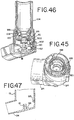
- the indicator assembly can include a single indicator member, or a plurality of (i.e., more than one) indicator members, shown for example as three co-axially mounted indicator members 50 in the various embodiments of FIGS. 1-4 , 16 , 22, 23 , 32 , 34, 37 , 40, 41 and 46 .
- the indicator assembly can be configured as a mechanical device or an electrical device, or a combination thereof, and can include without limitation various analog and digital readouts and indicia.
- an actuator member 70 is configured as a post member 72 moveably supported in the housing along an axis parallel to the longitudinal axis defined by the reciprocal movement of the container within the housing.
- a spring 88 is disposed around the post and biases the actuator member upwardly against the top surface 108 of the canister, or against a mounting portion secured thereto.
- a compression spring is shown in the Figures, it should be understood that cantilever, torsion, leaf and tension springs, and the like, would also work to bias the actuator member upwardly into engagement with the container.
- the springs can be made of metal or plastic.
- the container In operation, the container is moved longitudinally within the housing so as to depress the valve stem to the open position and thereby open the valve as explained above.
- the actuator member 70 As the container is moved downwardly within the housing, the actuator member 70 is moved longitudinally downward.
- the spring (not shown) within the container biases the container upwardly within the housing along the longitudinal axis such that the valve stem 110 is moved to the closed position within the container so as to close the valve, while the spring biases the actuator member upwardly.
- the actuator As the actuator is reciprocally moved, it selectively engages a ratchet gear 72, which in turn operably moves one or more the indicator members upon a predetermined number of reciprocal movements.
- the indicator members 50 are provided with indicia that are visible through one or more viewing windows 52.
- the indicia indicate to the user the number of doses that remain in or have been dispensed from the container.
- the indicia take the form of a color code, where, for example, a portion of the wheel is colored green to indicate the starting full position, a portion is colored yellow to indicate a medium fullness and a portion is colored red to indicate that the container is empty.
- other colors, shading or alphanumerical indicia can be provided on the indicator wheel to indicate the relative fullness or emptiness of the container.
- the indicator assembly includes three indicator members 50 coaxially mounted on an axle 56 and rotatable thereabout.
- Each of the indicator members is configured as an indicator wheel having a circumferential skirt with an outer circumferential surface 60 on which indicia (shown as numbers) are applied.
- the ratchet gear 72 is coaxially mounted with the indicator wheel.
- the ratchet gear 72 includes a plurality of teeth formed around its periphery.
- the ratchet gear is integrally molded with the indicator wheel, although it should be understood that the gear and wheel can be made separately and thereafter attached one to the other by welding, adhesive and the like.
- the first indicator member includes a resilient advancement member 62 that overlies the ratchet gear teeth of the second indicator member.
- the second indicator member includes an advancement member that overlies the ratchet gear teeth of the third indicator member.
- a housing 10 is shown as having a pair of engagement members 64 formed integrally with the housing and including ramped surfaces.
- a plurality of non-return members 66 extend from the housing and selectively engage the ratchet gear to ensure unidirectional rotation of the indicator member.
- the engagement members and non-return members are shown as being formed in or extending from a module housing, shown in FIGS. 3 and 16 and as described below, one of skill in the art should understand that those members or equivalent features could also be formed in or connected to the dispenser housing or actuator boot that supports the container as shown in FIG. 34, 37 and 38 or disposed on or connected to the container itself.
- the container In operation, the container is moved longitudinally within the housing 10 so as to depress the valve stem 110 to the open position so as to open the valve as explained above.
- the actuator 70 engages the ratchet gear 72 secured to the first indicator member and rotates the first indicator member a predetermined angular or incremented amount corresponding to the pitch of the teeth disposed around the periphery of the ratchet gear.
- the reciprocal movement of the container relative to the housing is repeated until the first indicator member 50, and its ratchet gear 72, are rotated one complete revolution.
- the predetermined number of reciprocal movements required to advance the first indicator member one revolution is equal to the number of teeth disposed about the periphery of the ratchet gear 72.
- the advancement member 62 of the first indicator member is brought into selective engagement with the engagement member 64, configured with the ramped surface formed in the housing.
- the engagement member 64 biases a tooth portion of the advancement member 62 into engagement with one of the teeth of the ratchet gear 72 on the second indicator member.
- the advancement member 62 engages one of the teeth on the ratchet gear 72 of the adjacent (i.e., second) indicator member and advances the indicator member a predetermined incremental angular amount corresponding to the pitch of the ratchet gear teeth.
- incremental is meant to refer to the angular amount the indicator member is moved by the advancement of one actuation, which corresponds to the movement of one tooth, regardless of whether the indicating device is indicating the number of doses left (e.g., counting down) or indicating the number of doses administered (e.g., counting up).
- the resilient advancement member 62 clears the engagement member 64, it springs away from the ratchet gear such that further advancements of the first indicator member do not effect a rotation of the second indicator member until the first indicator member completes yet another cycle so as to again bring the advancement member into engagement with the next tooth of the second indicator member ratchet gear, and so on.
- the second indicator member with its advancement member similarly interacts with a second engagement member overlying the teeth of the third indicator member so as to selectively engage and advance the third indicator member a predetermined incremental amount for each complete rotation of the second indicator member. It should be understood that more indicator members could be similarly assembled to provide an incremental indicating device.
- a secondary or warning indicator member 300 is rotatably supported in the dispenser housing adjacent the indicator members about an axis parallel to and spaced apart from the axis of the indicator members 50.
- the warning indicator 300 has an outer circumferential surface with warning dosage indicia applied thereto.
- the warning dosage indicia takes the form of a color coding, for example a portion or zone of the surface is green, while another portion or zone is red.
- a plurality of zones is used, for example and without limitation two zones of green and red respectively, or three zones of green, yellow and red.
- alphanumeric characters, text messages etc. as herein described can be used as indicia.
- a surface of the indicator member perpendicular to the axis of rotation also can be configured with the indicia. The surface of the indicator member is visible through a viewing window 302 formed in the dispenser housing.
- the second indicator member 300 further includes at least one driven member 306, and preferably a plurality of driven members, configured in one embodiment as a teeth extending radially outward from the second indicator member on one side of the circumferential indicia surface.
- a drive member coupled to one of the indicator members and the driven members are configured and have sufficient lengths so as to mesh after a predetermined number of rotations of the first indicator member 50 configured with the drive member.
- the second indicator member 300 is also provided with a plurality of ratchet teeth 308 formed circumferentially around the axis of rotation on the side of the indicator member opposite the drive member.
- a non-return member extends from the dispenser housing or module housing and successively, selectively engages one or more of the ratchet teeth 308 so as to allow the second indicator member 300 to rotate in only one direction.
- Various embodiments incorporating a warning indicator are further disclosed in U.S. Patent Application No. 10/968,815, filed October 18, 2004 and entitled Indicating Device With Warning Dosage Indicator.
- the indicator assembly is arranged in an indicator module 90.
- the indicator module 90 is shaped to be received within the housing where it is disposed around a portion of the support block 16.
- the support block is spaced apart from the wall of the dispenser housing, otherwise referred to as the actuator boot, so as to form a donut-shaped socket in the bottom of the housing.
- the module includes a module housing 92 having an inner concave surface that is shaped to mate with an outer convex surface of the cylindrical support block and an outer convex surface that is shaped to mate with the inner concave surface of the housing which is also generally cylindrical. In this way, the module housing is shaped to be received within the socket formed around the support block.
- the module housing has a semicircular shape and fits around a portion of the support block opposite the orifice opening so as to not interfere with the dispensing of the medicament, or the airflow transmitting the medicament to the patient. In this way, the module is maintained rearwardly of the midpoint of the support block.
- the module, or module housing can be configured in any number of different sizes and shapes so as to be accommodated in a variety of housings or cap assemblies, with or without support blocks and the like.
- the module housing can be made of a single piece, or from two or more pieces joined to form the housing.
- the module can be secured within the housing by any number of conventional means, including the use of fasteners or adhesive.
- the module can simply be press fit into the socket formed between the support block and housing wall.
- the indicia are applied to a circumferential surface 60 of the indicator wheel, for example in the form of numbers ranging from 0 to 9, with the ratchet gear on the indicator member having 10 teeth.
- the three, or more or less, indicator members can be preset to the maximum number of dosages contained within the container, with the indicia, or in this case numbers, arranged about the periphery of the indicator wheel, such that successive, sequential actuations of the container cause the indicator members to count down.
- the indicator members are assembled such that the zero (0) of each indicator member is displayed in the viewing window to the user.
- the container is then actuated by the user such that the first indicator member rotates within the housing to sequentially display the number of doses that have been dispensed from 1 to 9.
- the indicator member completes a single revolution, by virtue of the ten teeth preferably formed about the ratchet gear which correspond to the predetermined number of actuations, and causes the second indicator member to advance one number from 0 to 1 as the first indicator member again displays a 0 such that the two members together indicate that 10 dosages have been dispensed.
- the first indicator member is again rotated by successive actuations until another single rotation is completed to further rotate the second indicator to reveal the 2, so as to indicate that 20 dosages have been dispensed.
- the third indicator member is advanced to reveal a 1 in the viewing window with the first and second indicator members revealing a 0, and so on.
- FIGS. 1-5 are shown as being mounted in the indicator module, one of skill in the art should understand that the assembly, including the axle, indicator members, ratchet gears, actuator member and spring could be mounted directly in the dispenser housing or actuator boot that supports the container, as shown for example in FIG. 34 , 41 and 46 . Similarly, the engagement member, or members, and non-return member, or members, could be formed in the dispenser housing that supports the container, otherwise referred to as the actuator boot, as shown in FIG. 38 .
- a connector 4 connects the container and the dispenser housing, and maintains the connection therebetween as the container is moved between the engaged and disengaged positions.
- the term "connected” as used herein means that two or more members or components are coupled, whether directly or indirectly, for example with an intervening member or component.
- the container is connected to the dispenser housing when it is connected to the indicator assembly, which in turn is connected to the dispenser housing.
- the term "fixedly connected,” or variations thereof, means that one component connected to another is not meant to be disconnected during the normal operation of the device and without undue force, while “releasably connected,” means that one component is meant to be disconnected during such normal operation and without undue force.
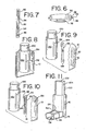
- the connector includes mounting portion 30 mounted to the container.
- the mounting portion shown in FIG. 6 , includes a locking ring or collar 32 that is engaged with the hub 106, for example by snap-fit, and an annular wall that surrounds the end portion of the container.
- the mounting portion can include a longitudinal slit to allow the collar to be snap fit onto the container.
- the mounting portion includes a pair of follower members 34 extending from the annular wall on opposite sides thereof. Each follower member includes a stem 36 and cap portion 38.
- the connector further includes a pair of longitudinally extending guide portions 40 formed along an interior of the dispenser housing.
- Each guide defines a track 42.
- the guides include a top portion 44 that extends longitudinally from the top of the dispenser housing.
- the track 42 terminates at an upper portion of the guide 44 to define a travel limiting stop 46.
- the follower members 34 formed on the mounting portion are directly mounted in the track 42, with the head or cap portions 38 being retained by the guide 40, such that the container can be translated relative to the guide in the track between the engaged and disengaged positions.
- the container can also be rotated relative to the dispenser housing about an axis 48 defined by the follower members so as to provide access to the interior of the dispenser housing 10.
- the mouthpiece 24 is rotatably connected to an upper portion 6 of the dispenser housing.
- the upper portion which also includes the support block 16 includes a pair of axles 8 extending laterally outward from an exterior thereof.
- the housing includes a catch component 54 formed along a top of a mouthpiece opening 78.
- the mouthpiece includes a pair of tabs 74 defining openings 76 or sockets shaped to receive the axles 8.
- the mouthpiece further includes a catch component 58, that releasably engages the catch component 54 on the upper housing portion to releasably secure the mouthpiece in a closed, operable dispenser condition.
- the mouthpiece can be rotated or pivoted about an axis 80 defined by the axles to a cleaning position, wherein the user is provided with access to the interior of the upper portion of the dispenser housing, including the support block.
- the connector further includes a pair of extension members 82.
- Each extension member has a follower member 86 protruding laterally therefrom and a longitudinal track 84, having terminal upper and lower ends 94, 96 defining travel limiting stop portions.
- the follower members 34 on the mounting portion are mounted in the tracks 84 of the extension members respectively and translate relative thereto.
- the follower members 34 can be rotated about the axis 38 relative to the extension members.
- the extension members 82 can be translated by moving the follower members 86 thereof in the tracks 42 formed in the dispenser housing.
- the extension members 82 can also be rotated relative to the dispenser housing, as shown in FIGS. 4 and 5 , by rotating the extension members about an axis 98 defined by the follower members 86 thereof.
- the container 100 is moved from the engaged to the disengaged position.
- the container 100 translates relative to the extension member 82, while the extension member translates relative to the dispenser housing 10 after the mounting portion follower members 34 are engaged with the top travel limiting stop portion 96.
- the container 100 can be rotated relative to the dispenser housing 10 and the extension members 82.
- the extension member 82 can also be rotated relative to the dispenser housing 10. In this way, the container can be translated and rotated, or moved, so as to provide access to the cavity 12 of the dispenser housing, for example to clean the housing, while maintaining a connection between the container and the dispenser housing.
- the mounting portion 130 includes a wall portion that extends longitudinally along the side of the container.
- the mounting portion forms a pair of guides each having a track 132.
- a pair of follower members 134 extend laterally inward from an interior surface of the dispenser housing and are engaged in the tracks.
- the container and mounting portion which is attached to the container, are translated relative to the follower members 134 and dispenser housing 10.
- the follower members are formed on an extension portion of the dispenser housing that extends from the top thereof such that the container and mounting portion can also be rotated relative to the dispenser housing.
- the extension member 82 of FIG. 7 is incorporated into the embodiment of FIG. 8 , but with the follower member 86 of the extension members engaged in the tracks 132 of the mounting portion and the follower members 134 of the dispenser housing engaged in the tracks 84 of the extension members.
- the container and mounting portion 130 can be translated and/or rotated relative to the extension members 82 while the extension members can be translated and rotated relative to the dispenser housing 10.
- the dispenser housing includes a pair of guides 40 each defining a track 42.
- a pair of extension members 182 each include a pair of longitudinally spaced follower members 184, 186 extending from opposite sides of the extension member on opposite ends thereof.
- the follower members 184, 186 are engaged respectively with the tracks 132, 42 formed on the mounting portion and dispenser housing to allow the container and mounting portion to be translated and rotated relative to the extension member and dispenser housing, and also to allow the extension member 182 to be translated and rotated relative to the dispenser housing 10, such that the container can be completely removed from the dispenser housing, but remain connected thereto.
- extension members can also be used to connect the container and the dispenser housing.
- FIGS. 1-15 maintain the connection between the container 100 and dispenser housing 10 so as to avoid a count corruption of the indicating device relative to the container, but also permit the container to be moved to a disengaged position so as to allow the dispenser housing to be cleaned.
- amounting portion 112 includes a plurality (shown as three) longitudinally extending arms 114 each having a catch portion 120 formed on a free end thereof.
- a collar portion 116 of the mounting portion includes longitudinal slits 122, allowing the collar portion to be snap fitted around the neck 188 of the container.
- the dispenser housing includes a corresponding plurality of guides 118 each defining an opening or track.
- the arms 114 are disposed through the guides 118 such that the catch portions 120 engage a bottom of the guides and prevent the container from being removed therefrom when moved to a disengaged position.
- the catch portions 120 engage the bottom of the guides 118 as the container is moved to the engaged condition and thereafter maintains the container in the engaged position, thereby precluding it from being moving to the disengaged position.
- the arms 114 move relative to the guides 118 as the container 100 is reciprocally moved relative to the support block 16.
- the indicator assembly is mounted directly in the bottom of the dispenser housing, although it should be understood that a module housing could also be used.
- the arms 114 and catch portions 120 are inserted through openings 91 formed in the top of a module housing 90 arid defining guides.
- the catch portions 120 engage a bottom of the top wall of the housing and prevent the container from being disengaged from the module housing 90 when the container is moved to a disengaged position.
- the catch portions 120 engage the module housing 90 as the container is moved to the engaged condition and thereafter maintains the container in the engaged position, thereby precluding it from being moving to the disengaged position.
- the arms 114 move relative to the openings 91 and module housing 90 as the container 100 is reciprocally moved relative to the support block 16.
- the module housing 90 can be fixedly secured to the dispenser housing, for example by snap-fit engagement with one or more tabs 93 that engage, for example and without limitation, a front, vertical surface and a top surface of the module housing 90.
- the module housing can also be attached by friction fit, welding (e.g., sonic), with adhesives, or some combination of the above.
- the dispenser housing 10 does not need to be modified or otherwise altered from a configuration wherein a dose indicator is not used. Rather, the user simply secures the module housing 90 in the bottom of the dispenser housing 10, for example with adhesives or friction fit, and thereafter secures the container 100 to the module housing 90, for example with the arms 114.
- the indicating device is mounted in a bottom portion 124 of the dispenser housing, either directly or with a module housing.
- An upper portion 126 of the dispenser housing is connected to the bottom portion.
- the bottom and upper portions can be made as separate members, which are affixed to one another for example with mechanical fasteners (e.g., snap fit), adhesives, ultrasonic welding or the like.
- the upper portion includes a plurality of downwardly inclined lugs 128 or arms that snap fit around the container 100 as the neck of the container is slid past the lugs and as the valve stem 110 is inserted into the support block 16, with the lugs engaging the shoulder 180 of the container.
- the lugs, or catch portions can be spaced from the support block such that they maintain the container in an engaged position at all times, or they can be spaced upwardly such that the container can be moved to a disengaged position, but cannot be removed from the dispenser housing.
- the catch portions engages the ferrule portion of the container to prevent it from being disengaged from the dispenser housing, while allowing the container to move downwardly relative to the catch portions to dispense a dose of substance.
- the lugs or arms 128, i.e. catch portions can be formed in the lower portion 124, which can include an integrally formed mouthpiece, or can have a separate mouthpiece 24 rotatably or pivotally connected thereto.
- the lugs 128 function in the same way as described above, but in this embodiment permit the removal of the upper portion 126 of the dispenser housing, for example to permit cleaning of the device.
- One of the upper or lower portions can be configured with a stepped in wall 214 and shoulder 216, which receives the other portion by way of a friction fit.
- one or the other of the upper and lower portion can be provided with one or more bumps or protuberances to frictionally or snap-fittingly engage the other component.
- the dispenser housing includes a lower or bottom portion 124, an upper portion 126 and a mouthpiece 24 rotatably connected to the lower portion 124.
- the mouthpiece is formed integrally with the lower portion 124.
- the upper portion 126 is made of a clear plastic, or is otherwise see-through, such that the user can view the container, for example to read a label or prescription applied thereto.
- the entirety of the upper portion can be made see-through, or it can be provided with a see-through viewing window permitting viewing of a portion of the container, with the remainder of the upper portion not being see-through.
- the see-through aspect of the upper portion can be important, for example, if the upper portion and container are fixed to the lower portion such that they are not removeable therefrom, for example to permit viewing of the label affixed to the container.
- the lower portion and mouthpiece can also be made see-through.
- the upper portion 126 is removably attached to the lower portion 124 to facilitate cleaning of the device.
- one of the upper or lower portions can be configured with a stepped in wall 214 and shoulder 216, which receives the other portion by way of a friction fit.
- one or the other of the upper and lower portion can be provided with one or more bumps or protuberances to frictionally or snap-fittingly engage the other component.
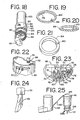
- a locking ring 202 is secured in the lower portion, for example and without limitation by friction fit, snap fit, welding, adhesives and/or some combination thereof.
- the ring has a central opening 204 formed by a scalloped inner periphery 206 defined by a circular opening 208 having a plurality (shown as six) of semi-circular openings 210 spaced around the periphery of the circular opening.
- the combination of openings forms a plurality (shown as six) of gripping tabs 212 or catch portions.
- the tabs 212 engage the container, and in particular surround the neck 188 thereof, with a snap-fit, such that the container is maintained in an engaged position with the support block, but cannot be disengaged from the lower portion by way of the locking ring 202 engaging the shoulder 180 of the container.
- the circulatory openings 210 or cut-outs permit air flow past or through the ring during actuation of the container. It should be understood that more or less openings could be formed.
- the ring can be formed with a single, central circular opening to receive the container, with other openings formed through the ring and spaced from the central opening if necessary to permit air flow.
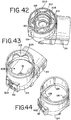
- a dispensing device includes a cap member 136 formed from a resilient, flexible material, such as rubber.
- the cap is secured over the container once it is positioned in the engaged position.
- the cap can be fixedly secured to the dispenser housing with adhesives, fasteners and the like.
- the user actuates the container by pushing on the rubber cap, which deforms as the container moves longitudinally downward relative to the dispenser housing.
- the dispenser housing is provided with a plurality of vent holes 138 that allow air to escape when the cap member is depressed to actuate the container.
- FIGS. 31-46 can be configured so as to maintain the container in the engaged position once it is installed in the dispenser housing, meaning that it cannot be moved to the disengaged position with the valve stem removed from the support block.
- a single container is associated with a corresponding indicating device such that the count of dosages cannot be corrupted by removing the container from the dispenser housing and using it with a different housing.
- the mounting arrangement permits the container to reciprocally move in the longitudinal direction relative to the support block so as to allow dosages of substance to be dispensed.
- another dispensing device includes a connector including a tether 140.
- a cap member 142 or other mounting portion, includes an anchor 144.
- the cap member 142 is mounted to the container, either fixedly or releasably.
- the cap member 142 includes a plurality of interior radially extending ribs 148 that engage the end of the container with a friction fit.
- the cap member 142 includes a plurality of resilient tabs or fingers 150, which act as engagement members to engage the container.
- the cap member 242 is formed in a disc shape, with a bottom of the cap being attached to the bottom of the container with adhesives, or other suitable attachment devices.
- an anchor 144 is provided for connection to one end of the tether 140.
- the cap member 242 has a key hole formed therein and defining an anchor, with the key hole including a slot 244 and a hole 246 formed in a bottom of the cap member.
- the tether 140 includes a knot or stop portion formed on an end thereof which extends through the hole 246 in an engaged configuration, while the tether lies in the slot and extends from the cap member through an opening 248 in the side thereof defined by the slot. The opposite end of tether is secured to an anchor on the dispenser housing as explained below.
- the cap member 142 includes a slot 244 opening to the side thereof at an opening 248 such that the tether lies in the slot between the cap member and the bottom of the container and extends through the slot.
- the cap member further includes a hole 246 configured to secure an enlarged end of the tether.
- the dispenser housing includes an anchor 146, which can be located on the exterior or interior of the housing.
- the tether is made of a stretchable material, such as an elastomeric material, e.g. rubber or silicone.
- the tether is made of a non-extensible material, which may or may not be contained in a retraction mechanism that winds and stores the tether. Opposite ends of the tether 140 are secured to the anchors 144, 146.
- the user moves the container 100 from an engaged position to a disengaged position, which can include removing the entire container from the dispenser housing, for example to clean the housing.
- the tether maintains the connection of the container with the dispenser housing such that the dosage count is not corrupted.
- a dispenser device includes a dispenser housing 10, a key device 152 and an indicating device 90.
- the key device 152 has a mounting portion 158 connected to the container, for example by snap fit to the hub or neck of the container.
- the mounting portion 158 includes a collar 32 as disclosed above with respect to FIG. 6 .
- the key device 152 further includes first and second rotatable rings 154, 156, shown for example in FIG. 21 , which are rotatably secured to the mounting portion with the first ring disposed circumferentially around the second ring.
- the mounting portion includes an edge portion on the bottom thereof that supports the rings.
- Each ring 154, 156 includes an opening 160, 162, or key passageway, formed in a bottom surface thereof.
- one or both of the rings includes a key portion extending downwardly therefrom.
- the key portion can be configured as a triangular tab member for example and without limitation.
- the indicating device is connected to the dispenser housing as explained above.
- the indicating device further includes first and second gears 164, 166 rotatably mounted to the top thereof, e.g. sit in the base housing, and are rotatable about the longitudinal axis.
- the first and second gears include first and second key portions 168, 170 extending upwardly therefrom. It should be understood that one or both of the first and second gears could also be configured with a key passageway.
- the key portions 168, 170 are disposed in the key passageways 160, 162 as the container is moved to an engaged position with the valve stem engaged with the dispenser housing. Initially, the key passageways and key portions are aligned, for example side by side. When the container is moved to the disengaged position, the first and second key portions are removed from said first and second key passageways respectively.
- Each of the first and second gears 164, 166 includes a plurality of gear teeth extending from a bottom thereof and arranged circumferentially around the gears.
- the teeth of the outer, first gear 164 are engaged with a drive gear 172 rotatably mounted in the module housing, as shown in FIGS. 23 .
- the drive gear is coaxially mounted with a ratchet gear 174.
- the actuator 70 shown in FIG. 24 , includes a finger or tab member 176 that selectively engages the teeth of the ratchet gear 174 and rotates the gear an incremental amount upon each reciprocal movement of the actuator 70 and container 100.
- the drive gear 172 rotates with the ratchet gear 174 and thereby rotates the outer gear 164 an incremental amount.
- the key portion 168 engages the ring 154 in the key passageway 160 and moves the ring on the container mounting portion.
- an advancement member 178 extending radially and circumferentially along the inside of the outer gear, is biased inwardly by an engagement member formed on the indicator housing 92 into engagement with one of the teeth formed on the inside gear 166 so as to advance the inside gear 166.
- the inside gear 166 in turn rotates the second ring 156 by way of engagement of the key portion 170 with the key passageway 162.
- the user reciprocally moves the container 100 relative to the valve stem 110 and dispenses a dosage of substance from the container upon each reciprocal movement of the canister.
- the first gear 164 is rotated by the drive gear 172 a first incremental amount in response to each reciprocal movement of the canister, and selectively engages the second gear 166 with the first gear upon a predetermined number of reciprocal movements of the canister.
- the first gear rotates the second gear a second incremental amount.
- the first and second gears, and corresponding first and second rings are moved to different positions, they define a changing unique key pattern corresponding to the number of doses that have been dispensed.
- the container 100 is configured with a unique indicia that matches a corresponding unique indicia located on the housing 10, the indicating device or assembly, or a combination of the housing and indicating device.
- the container and housing can be configured with a matching color or alpha numeric character, or a combination of both, such that the user is advised that a particular container is associated with a particular housing.
- both the container and housing can be configured with a label having a particular color (e.g., red) and an alpha-numeric indicia, e.g., "B263.” In this way, the user is advised that the container matches the dispenser and is assured that the count indication on the indicating device associated with that dispenser corresponds to that container.
- This identification system can be used by itself, i.e. as a primary linking/identification tool, or as an auxiliary identification tool used in cooperation with the other embodiments and connector devices disclosed herein.
- each container and corresponding housing/indicating device is provided with a unique indicia that is not duplicative of indicia used with any other housing/indicating device.
- the indicia may be reused after the passage of time, for example a certain time beyond the expiration of any particular lot of medicament, such that an infinite number of indicia is not required.
- containers and housings/indicating devices dispensed to a particular user are configured with unique indicia, for example by having the pharmacy or other retailer maintaining records and assigning new indicia to refills and new prescriptions so as to preserve the uniqueness relative to that particular user.
- other users may randomly be assigned the same indicia as the indicia used by a particular user, but the uniqueness is preserved for each user.
Landscapes
- Health & Medical Sciences (AREA)
- Engineering & Computer Science (AREA)
- Life Sciences & Earth Sciences (AREA)
- Public Health (AREA)
- Animal Behavior & Ethology (AREA)
- Veterinary Medicine (AREA)
- Anesthesiology (AREA)
- Biomedical Technology (AREA)
- Heart & Thoracic Surgery (AREA)
- Hematology (AREA)
- General Health & Medical Sciences (AREA)
- Pulmonology (AREA)
- Bioinformatics & Cheminformatics (AREA)
- Biophysics (AREA)
- Emergency Medicine (AREA)
- Containers And Packaging Bodies Having A Special Means To Remove Contents (AREA)
- Medical Preparation Storing Or Oral Administration Devices (AREA)
Claims (24)
- Spender, der Dosierungen einer Substanz abgibt, umfassend:einen Behälter (100) mit einem Endabschnitt und einem Ventilkörper (110), der sich von dem Endabschnitt erstreckt;ein Spendergehäuse (10) mit einer Oberseite, einem Boden (22) und einem sich in Längsrichtung erstreckenden Hohlraum (12), der eine Öffnung in der Oberseite definiert, wobei der Boden eine Vertiefung (18) definiert;eine Anzeigevorrichtung, die mit dem Spendergehäuse verbunden ist, wobei die Anzeigevorrichtung eine Anzeige (50) umfasst, die Dosierungszeichen umfasst; undeinen Verbinder (4), der das Spendergehäuse und den Behälter verbindet;wobei der Behälter zwischen einer Verbindungsposition, in der der Ventilkörper in der Vertiefung angeordnet ist, und einer Lösungsposition, in der der Ventilkörper aus dem Schacht entfernt ist, bewegbar ist,wobei der Verbinder eine Verbindung zwischen dem Behälter und dem Spendergehäuse aufrechterhält, wenn der Behälter zwischen der verbunden und der gelösten Position bewegt wird, undwobei der Verbinder einen an dem Behälter montierten Befestigungsabschnitt (30) aufweist,wobei der Befestigungsabschnitt mit dem Spendergehäuse verbunden ist,dadurch gekennzeichnet, dassdas Spendergehäuse oder der Befestigungsabschnitt mindestens eine sich in Längsrichtung erstreckende Führung (40) aufweist, und wobei der andere von dem Spendergehäuse und dem Befestigungsabschnitt beweglich mit der Führung verbunden ist und relativ zu der Führung beweglich ist, wenn der Behälter zwischen der verbunden und der gelösten Position bewegt wird.
- Spender nach Anspruch 1, wobei der Befestigungsabschnitt einen Kragen (32) aufweist, der mit dem Endabschnitt des Behälters in Eingriff steht.
- Spender nach Anspruch 1, wobei die Führung eine Schiene (42) aufweist.
- Spender nach Anspruch 3, wobei das Gehäuse des Spenders oder der Befestigungsabschnitt ein Mitnehmerelement (34) aufweist, das beweglich in der Schiene (42) angeordnet ist.
- Spender nach Anspruch 4, wobei das Spendergehäuse ferner ein Mundstück (24) aufweist, das schwenkbar mit dem Boden des Behälters verbunden ist, wobei das Mundstück zwischen einer Spenderposition und einer Reinigungsposition schwenkbar ist.
- Spender nach Anspruch 3, wobei der Verbinder ferner ein Verlängerungselement (82) aufweist, das den Befestigungsabschnitt und das Spendergehäuse verbindet.
- Spender nach Anspruch 6, wobei das Verlängerungselement schwenkbar mit dem Befestigungsabschnitt und mit dem Spendergehäuse verbunden ist.
- Spender nach Anspruch 7, wobei das Verlängerungselement mindestens einen Mitnehmer (86) aufweist, der in die Schiene (42) eingreift.
- Spender nach Anspruch 8, wobei die Schiene eine erste Schiene und der mindestens eine Mitnehmer einen ersten Mitnehmer umfasst, und wobei das Verlängerungselement ferner eine zweite Schiene umfasst, und wobei der andere Abschnitt, d.h. der Montageabschnitt oder das Spendergehäuse, einen zweiten Mitnehmer umfasst, der in die zweite Schiene eingreift.
- Spender nach Anspruch 8, wobei die Schiene eine erste Schiene umfasst und der mindestens eine Mitnehmer einen ersten Mitnehmer umfasst, und wobei das Verlängerungselement ferner einen zweiten Mitnehmer umfasst, und wobei das andere Element, d.h. der Montageabschnitt oder das Spendergehäuse, eine zweite Schiene umfasst, wobei der zweite Mitnehmer in die zweite Schiene eingreift.
- Spender nach Anspruch 1, wobei der gesamte Behälter durch die Öffnung in der Oberseite bewegt wird und außerhalb des Hohlraums angeordnet ist, wenn er sich in der gelösten Position befindet.
- Spender nach Anspruch 1, wobei mindestens ein Abschnitt des Behälters in dem Hohlraum angeordnet bleibt, wenn er sich in der gelösten Position befindet.
- Spender nach Anspruch 1, wobei die Anzeigevorrichtung fest an dem Spendergehäuse befestigt ist.
- Spender nach einem der Ansprüche 1 bis 13, wobei das Spendergehäuse mindestens eine Führung (40) aufweist; der Behälter einen Ventilschaft aufweist, der mit dem Spendergehäuse in Eingriff steht, wobei der Behälter relativ zu dem Ventilschaft zwischen mindestens einer ersten und einer zweiten Position beweglich ist; und der Verbinder mindestens einen Arm (114) mit einem Sperrabschnitt (120) umfasst, wobei der Arm durch die mindestens eine Führung angeordnet ist, wobei der Sperrabschnitt mit der Führung in Eingriff steht, so dass verhindert wird, dass sich der Ventilschaft von dem Spendergehäuse löst, wobei der mindestens eine Arm relativ zu der Führung beweglich ist, wenn der Behälter zwischen der ersten und zweiten Position bewegt wird.
- Spender nach Anspruch 14, wobei der Verbinder mit dem Behälter verbunden ist.
- Spender nach Anspruch 15, bei dem der Verbinder einen Kragen aufweist, der mit dem Behälter in Eingriff steht.
- Spender nach Anspruch 14, wobei das Spendergehäuse ein Modulgehäuse und einen in dem Modulgehäuse angeordneten Indikator umfasst, wobei die mindestens eine Führung in dem Modulgehäuse ausgebildet ist.
- Spender nach einem der Ansprüche 1 bis 13, wobei das Spendergehäuse mindestens einen Sperrabschnitt (120) aufweist; der Behälter einen Ventilschaft umfasst, der mit dem Spendergehäuse in Eingriff steht und einen Hals und einen Hülsenabschnitt umfasst, wobei der Behälter relativ zum Ventilschaft zwischen mindestens einer ersten und einer zweiten Position beweglich ist, wobei der Sperrabschnitt mit dem Hülsenabschnitt in Eingriff steht, so dass verhindert wird, dass sich der Ventilschaft von dem Spendergehäuse löst, und wobei der Behälter relativ zum Sperrabschnitt beweglich ist, wenn der Behälter zwischen der ersten und der zweiten Position bewegt wird.
- Spender nach Anspruch 18, wobei das Spendergehäuse einen unteren Abschnitt (124) und einen oberen Abschnitt (126) aufweist.
- Spender nach Anspruch 18, wobei zumindest der obere Abschnitt zumindest teilweise durchsichtig ist.
- Spender nach Anspruch 19, wobei der mindestens eine Sperrabschnitt mit dem unteren Abschnitt verbunden ist.
- Spender nach Anspruch 21, wobei der untere Abschnitt abnehmbar mit dem oberen Abschnitt verbunden ist.
- Spender nach Anspruch 18, der einen Verriegelungsring (202) aufweist, der mit dem Spendergehäuse verbunden ist, wobei der Verriegelungsring den mindestens einen Sperrabschnitt aufweist.
- Spender nach Anspruch 23, wobei der Verriegelungsring mindestens eine zentrale Öffnung, die so geformt ist, dass sie den Hals aufnimmt, und mindestens eine Zirkulationsöffnung (210), die so betätigbar ist, dass sie einen Luftstrom an dem Verriegelungsring vorbei ermöglicht, definiert.
Applications Claiming Priority (3)
| Application Number | Priority Date | Filing Date | Title |
|---|---|---|---|
| US64509505P | 2005-01-20 | 2005-01-20 | |
| US67122005P | 2005-04-14 | 2005-04-14 | |
| PCT/IB2006/000084 WO2006077486A1 (en) | 2005-01-20 | 2006-01-19 | Dispensing device |
Publications (3)
| Publication Number | Publication Date |
|---|---|
| EP1838371A1 EP1838371A1 (de) | 2007-10-03 |
| EP1838371A4 EP1838371A4 (de) | 2014-04-02 |
| EP1838371B1 true EP1838371B1 (de) | 2020-09-09 |
Family
ID=36692010
Family Applications (1)
| Application Number | Title | Priority Date | Filing Date |
|---|---|---|---|
| EP06703451.2A Expired - Lifetime EP1838371B1 (de) | 2005-01-20 | 2006-01-19 | Abgabevorrichtung |
Country Status (7)
| Country | Link |
|---|---|
| US (4) | US7743945B2 (de) |
| EP (1) | EP1838371B1 (de) |
| JP (2) | JP5189369B2 (de) |
| CN (1) | CN101810901B (de) |
| CA (2) | CA2592413C (de) |
| MX (1) | MX2007008752A (de) |
| WO (1) | WO2006077486A1 (de) |
Families Citing this family (43)
| Publication number | Priority date | Publication date | Assignee | Title |
|---|---|---|---|---|
| WO1999036115A2 (en) | 1998-01-16 | 1999-07-22 | 1263152 Ontario Inc. | Indicating device for use with a dispensing device |
| FR2871450B1 (fr) * | 2004-06-14 | 2006-09-22 | Valois Sas | Dispositif de distribution de produit fluide |
| CA2592413C (en) | 2005-01-20 | 2015-11-17 | Trudell Medical International | Dispensing device having a connector between the housing and container |
| US8141550B2 (en) | 2006-08-01 | 2012-03-27 | Trudell Medical International | Dispensing device |
| WO2008097645A1 (en) * | 2007-02-08 | 2008-08-14 | Aerovectrx Corporation | Aerosol delivery systems and methods |
| JP5385793B2 (ja) * | 2007-02-27 | 2014-01-08 | アイバックス ファーマシューティカルズ アイルランド | 計量式吸入器のキット |
| EP2077132A1 (de) | 2008-01-02 | 2009-07-08 | Boehringer Ingelheim Pharma GmbH & Co. KG | Abgabevorrichtung, Aufbewahrungsvorrichtung und Verfahren zur Abgabe einer Formulierung |
| DE202008013903U1 (de) * | 2008-10-17 | 2010-04-15 | Ophardt Hygiene-Technik Gmbh + Co. Kg | Spender mit elektronischem Zähler |
| US10011906B2 (en) | 2009-03-31 | 2018-07-03 | Beohringer Ingelheim International Gmbh | Method for coating a surface of a component |
| WO2010133294A2 (de) | 2009-05-18 | 2010-11-25 | Boehringer Ingelheim International Gmbh | Adapter, inhalationseinrichtung und zerstäuber |
| DE202009015766U1 (de) * | 2009-11-17 | 2010-03-25 | Ingo-Manufacturing Ltd., Ballymote | Fluidspender |
| EA026241B1 (ru) | 2009-11-25 | 2017-03-31 | Бёрингер Ингельхайм Интернациональ Гмбх | Распылитель |
| JP5658268B2 (ja) | 2009-11-25 | 2015-01-21 | ベーリンガー インゲルハイム インターナショナル ゲゼルシャフト ミット ベシュレンクテル ハフツング | ネブライザ |
| US10016568B2 (en) * | 2009-11-25 | 2018-07-10 | Boehringer Ingelheim International Gmbh | Nebulizer |
| WO2011160932A1 (en) | 2010-06-24 | 2011-12-29 | Boehringer Ingelheim International Gmbh | Nebulizer |
| WO2012130757A1 (de) | 2011-04-01 | 2012-10-04 | Boehringer Ingelheim International Gmbh | Medizinisches gerät mit behälter |
| US9827384B2 (en) | 2011-05-23 | 2017-11-28 | Boehringer Ingelheim International Gmbh | Nebulizer |
| USD748247S1 (en) * | 2011-06-01 | 2016-01-26 | Earigate Inc. | Eyewash device |
| GB201118845D0 (en) * | 2011-11-01 | 2011-12-14 | Euro Celtique Sa | Dispenser |
| WO2013152894A1 (de) | 2012-04-13 | 2013-10-17 | Boehringer Ingelheim International Gmbh | Zerstäuber mit kodiermitteln |
| EP3030298B1 (de) | 2013-08-09 | 2017-10-11 | Boehringer Ingelheim International GmbH | Vernebler |
| PL2835146T3 (pl) | 2013-08-09 | 2021-04-06 | Boehringer Ingelheim International Gmbh | Nebulizator |
| EA035261B1 (ru) | 2014-05-07 | 2020-05-21 | Бёрингер Ингельхайм Интернациональ Гмбх | Небулайзер и контейнер |
| HUE055604T2 (hu) | 2014-05-07 | 2021-12-28 | Boehringer Ingelheim Int | Porlasztó |
| AU2015257878B2 (en) | 2014-05-07 | 2019-08-08 | Boehringer Ingelheim International Gmbh | Container, nebulizer and use |
| US20160012701A1 (en) * | 2014-07-08 | 2016-01-14 | Chi Lu | System and method for a smart substance dispenser sleeve |
| CA2962947C (en) * | 2014-09-29 | 2021-02-23 | Dermira, Inc. | Device and method for dispensing a drug |
| JP6818008B2 (ja) | 2015-07-20 | 2021-01-20 | パール セラピューティクス,インコーポレイテッド | エアロゾル送達システムおよび関連する方法 |
| USD809127S1 (en) * | 2016-04-05 | 2018-01-30 | 3M Innovative Properties Company | Inhaler refill assembly |
| FR3050114B1 (fr) * | 2016-04-15 | 2021-12-03 | Aptar France Sas | Dispositif de distribution de produit fluide synchronise avec l'inhalation. |
| US20170361036A1 (en) * | 2016-06-15 | 2017-12-21 | Virgilant Technologies Limited | Electronic inhaling device |
| GB201615186D0 (en) * | 2016-09-07 | 2016-10-19 | 3M Innovative Properties Co | Energy storage mechanism for an inhaler |
| US10384022B2 (en) | 2017-02-09 | 2019-08-20 | Packaging Concepts Associates Holdings, Inc. | Hand-held dose-dispensing pressurized spray inhaler with child restraint capability |
| GB201702407D0 (en) | 2017-02-14 | 2017-03-29 | Norton (Waterford) Ltd | Inhalers and related methods |
| GB201702406D0 (en) | 2017-02-14 | 2017-03-29 | Norton (Waterford) Ltd | Inhalers and related methods |
| GB201702408D0 (en) | 2017-02-14 | 2017-03-29 | Norton (Waterford) Ltd | Inhalers and related methods |
| CN207040874U (zh) | 2017-05-25 | 2018-02-27 | 深圳市合元科技有限公司 | 一种可转动吸嘴的电子烟 |
| CN111447964B (zh) * | 2017-12-18 | 2022-10-04 | 勃林格殷格翰国际有限公司 | 用于将吸入器置于触发就绪状态的设备 |
| US11291182B2 (en) * | 2018-02-05 | 2022-04-05 | Nexfeed LLP | Device for facilitating and tracking the feeding of an animal |
| US11027909B2 (en) * | 2018-08-15 | 2021-06-08 | Gpcp Ip Holdings Llc | Automated flowable material dispensers and related methods for dispensing flowable material |
| US12064063B2 (en) | 2019-09-23 | 2024-08-20 | Gpcp Ip Holdings Llc | Automated toilet seat cover dispenser |
| US20240206687A1 (en) * | 2020-08-24 | 2024-06-27 | IM Pro Makeup NY LP | Systems, methods, and apparatuses for measuring and indicating product usage and providing user feedback with a pump actuated personal care product dispensing system |
| KR102871735B1 (ko) | 2021-03-23 | 2025-10-17 | 킴벌리-클라크 월드와이드, 인크. | 액체 제품 분배기용 저장조 조립체 |
Citations (2)
| Publication number | Priority date | Publication date | Assignee | Title |
|---|---|---|---|---|
| EP0938908A2 (de) * | 1998-02-27 | 1999-09-01 | Diemolding Corporation | Nebelkammer zur Benützung in einem Dosier-Inhalationsgerät |
| US20040089296A1 (en) * | 2002-10-24 | 2004-05-13 | Bowden Kevin D.J | Syringe and multi-dose inhaler adapter for a bag valve mask and automatic ventilator |
Family Cites Families (357)
| Publication number | Priority date | Publication date | Assignee | Title |
|---|---|---|---|---|
| US498851A (en) | 1893-06-06 | Printing-press | ||
| CA535518A (en) | 1957-01-08 | Dominion Rubber Company | Method and apparatus for splicing | |
| US152980A (en) * | 1874-07-14 | Improvement in oil-can stoppers | ||
| US385256A (en) * | 1888-06-26 | eggers | ||
| US165054A (en) | 1875-06-29 | Improvement in measuring-bottles | ||
| GB191111635A (en) | 1911-05-13 | 1911-08-31 | John Dowell | Improvements in or relating to Stoppers or the like for Bottles or other Receptacles. |
| FR451164A (fr) | 1912-11-28 | 1913-04-12 | Cie Des Hauts Fourneaux De Cha | Procédé de grillage des minerais de fer carbonatés |
| US1219858A (en) * | 1916-03-22 | 1917-03-20 | Herbert Harvey Patterson | Tallying device. |
| US2580292A (en) | 1946-04-30 | 1951-12-25 | Ira M Geary | Metered bottle closure |
| US2455962A (en) | 1946-07-25 | 1948-12-14 | Harold R Wheeler | Recording liquid dispenser |
| US2630027A (en) * | 1948-08-07 | 1953-03-03 | Elton T Barrett | Boring and facing head |
| US2587147A (en) * | 1950-05-08 | 1952-02-26 | Henry A Guion | Dose time indicator |
| US2644452A (en) | 1951-03-16 | 1953-07-07 | Frederick M Turnbull | Medicament vial |
| US2770711A (en) | 1953-03-16 | 1956-11-13 | Bowser Inc | Dispenser dial and sign illuminator |
| US2767680A (en) | 1954-01-26 | 1956-10-23 | Lermer Plastics Inc | Containers |
| FR1113454A (fr) | 1954-11-02 | 1956-03-29 | Perfectionnements aux bouchons de bouteilles | |
| US2883086A (en) * | 1955-12-12 | 1959-04-21 | American Machine & Metals | Liquid dispensing attachment for bottle, with means for automatically measuring a charge upon inversion of bottle |
| US3001524A (en) | 1956-03-21 | 1961-09-26 | Riker Laboratories Inc | Aerosol dispensing apparatus |
| US2841190A (en) | 1957-01-14 | 1958-07-01 | Scheck William | Refillable pressure spray device |
| US2953242A (en) | 1957-07-31 | 1960-09-20 | Gustave Miller | Container and time indicator |
| US2943730A (en) | 1958-07-29 | 1960-07-05 | Harold R Tregilgas | Pill dispenser |
| US2939597A (en) | 1959-04-01 | 1960-06-07 | Greene Edgeworth | Closures for sealing containers |
| US3085745A (en) * | 1961-06-23 | 1963-04-16 | Auberger Walter | Counter mechanism |
| US3073468A (en) * | 1961-09-15 | 1963-01-15 | Rap Inc | Tamper-proof closure cap |
| US3119557A (en) * | 1961-10-05 | 1964-01-28 | United States Steel Corp | Counter operator for pressurized paint can |
| DE1276294B (de) | 1961-12-04 | 1968-08-29 | Robert J Livingston | Verschluss fuer insbesondere Arzneimittel enthaltende Behaeltnisse mit Zaehl- oder Anzeigevorrichtung |
| US3170597A (en) * | 1962-02-12 | 1965-02-23 | Arthur M Reichenberger | Materials dispenser and recording means |
| US3148801A (en) | 1962-04-24 | 1964-09-15 | Sidney P Radeloff | Pouring spout with counting means |
| US3120318A (en) * | 1962-05-21 | 1964-02-04 | Herbert W Rigor | Locking container closure |
| US3189232A (en) | 1962-10-22 | 1965-06-15 | Park Plastics Co Inc | Dispenser for an aerosol container |
| GB1058636A (en) | 1962-11-06 | 1967-02-15 | Parkinson Cowan Appliances Ltd | Improvements in or relating to indexing mechanisms |
| US3187963A (en) | 1963-03-27 | 1965-06-08 | Johnson & Son Inc S C | Aerosol valve with means to lock same in the open position |
| US3151599A (en) | 1963-04-22 | 1964-10-06 | Robert J Livingston | Indicator-type closures |
| US3191867A (en) | 1963-10-23 | 1965-06-29 | Revlon | Atomizer |
| US3334627A (en) * | 1964-11-12 | 1967-08-08 | Sterling Drug Inc | Pivotal mouthpiece and actuator for an aerosol unit |
| US3240389A (en) * | 1964-12-24 | 1966-03-15 | Robertshaw Controls Co | Spray timer |
| US3361306A (en) * | 1966-03-31 | 1968-01-02 | Merck & Co Inc | Aerosol unit dispensing uniform amounts of a medically active ingredient |
| US3344951A (en) | 1966-04-18 | 1967-10-03 | Creative Packaging Inc | Ejection pill dispenser with indicating means |
| US3334731A (en) | 1966-07-11 | 1967-08-08 | Kathryn F Dale | Pill container and dispenser |
| US3402863A (en) | 1966-12-07 | 1968-09-24 | Scovill Manufacturing Co | Aerosol valve assembly having a dispenser cap and spacer collar |
| US3446179A (en) | 1967-03-14 | 1969-05-27 | Samuel Bender | Dose time indicator closure means for receptacles |
| DE6603758U (de) | 1967-05-06 | 1969-10-30 | Artur Pfaff | Dose zur aufnahme und dosierenden abgabe von massen in form eines nebels, eines schaumes oder einer paste |
| US3506004A (en) * | 1967-07-10 | 1970-04-14 | Dart Ind Inc | Inhalation device |
| US3419187A (en) | 1967-11-14 | 1968-12-31 | Peter P. Bazarnic | Device for measuring, registering and pouring |
| US3495567A (en) * | 1968-02-20 | 1970-02-17 | Creative Packaging Inc | Pill dispenser with indicating dial |
| US3477561A (en) | 1968-06-26 | 1969-11-11 | Martin Espinal | Recording pill dispenser |
| US3568629A (en) * | 1968-07-24 | 1971-03-09 | Herbert B Porter | Eccentric gearing means |
| GB1290484A (de) | 1968-10-02 | 1972-09-27 | ||
| US3511409A (en) | 1968-10-09 | 1970-05-12 | Ortho Pharma Corp | Tablet dispenser with hinged top and indicator ejecting wheel |
| US3549057A (en) | 1969-03-19 | 1970-12-22 | Ernesto M Perez | Metering dispenser for viscous materials |
| US3572282A (en) * | 1969-04-04 | 1971-03-23 | Ortho Pharma Corp | Tablet dispenser with circular tablet channel |
| BE754629A (fr) | 1969-08-11 | 1971-01-18 | Gen Time Corp | Distributeur automatique d'aerosol fonctionnant pendant de longues periodes |
| US3612349A (en) | 1969-09-05 | 1971-10-12 | Michael D Thomas | Pill dispenser having ratchet-action follower |
| US3845883A (en) | 1970-02-13 | 1974-11-05 | E Johnson | Measuring apparatus |
| US3753417A (en) | 1970-06-25 | 1973-08-21 | L Garby | Sequence indicating mechanism |
| US3654890A (en) * | 1970-09-22 | 1972-04-11 | Ortho Pharma Corp | Tablet dispenser |
| US3675604A (en) | 1970-10-08 | 1972-07-11 | Oxford Industries | Garment cutting and stacking method |
| US3688945A (en) | 1970-10-12 | 1972-09-05 | Bristol Myers Co | Recording tablet dispenser |
| GB1317315A (en) | 1970-12-17 | 1973-05-16 | English Numbering Machines | Mechanical impulse counter |
| GB1383761A (en) * | 1971-02-25 | 1974-02-12 | Woodcraft Dc | Inhalation device for use with an aerosol container |
| US3655952A (en) * | 1971-03-15 | 1972-04-11 | Portion Trol Liquor Systems In | Liquid dispenser counting mechanism |
| US3926326A (en) | 1971-03-31 | 1975-12-16 | Hermann Grau | Safety closure |
| US3831808A (en) | 1971-10-15 | 1974-08-27 | L Bender | Pill cartridge for a pill dispenser |
| US3796348A (en) * | 1971-10-18 | 1974-03-12 | W Zipper | Liquid metering and counting and dispensing means |
| CA1078796A (en) * | 1972-03-30 | 1980-06-03 | Takamitsu Nozawa | Liquid spraying device |
| US3802608A (en) * | 1972-04-10 | 1974-04-09 | Packard Instrument Co Inc | Liquid metering device with concentric pistons and unidirectional liquid flow |
| US3766882A (en) | 1972-04-21 | 1973-10-23 | D Babbitt | Dosage time indicator container |
| US3831812A (en) | 1972-09-01 | 1974-08-27 | Daltronics Int | Fluid dispensing system |
| US3792242A (en) * | 1973-01-02 | 1974-02-12 | G Hanson | Pocket size manual adding machine |
| US3848774A (en) | 1973-01-24 | 1974-11-19 | L Schimke | Measuring and dispensing cap |
| US3921568A (en) | 1973-07-25 | 1975-11-25 | William Joseph Fish | Self-adhering medication time reminder |
| US3887099A (en) | 1973-11-01 | 1975-06-03 | Poly Seal Corp | Container safety closure |
| US3950939A (en) * | 1974-02-22 | 1976-04-20 | Diehl | Digital display with stepping device |
| US3960713A (en) | 1974-08-16 | 1976-06-01 | The Raymond Lee Organization, Inc. | Medication timing sealing device |
| US4029033A (en) | 1974-09-18 | 1977-06-14 | The Continental Group, Inc. | Convenience opening of containers for liquid products |
| US4011829A (en) * | 1974-10-01 | 1977-03-15 | Doris Beryl Wachsmann | Closure having indicating means |
| US3977554A (en) | 1975-01-23 | 1976-08-31 | Allan Costa | Child-proof closure device for a container having a threaded neck portion |
| US3994421A (en) | 1975-09-29 | 1976-11-30 | American Cyanamid Company | Unitary therapeutic aerosol dispenser |
| US4074831A (en) | 1976-02-12 | 1978-02-21 | William John Roach | Liquid metering device with adjustable stops |
| US4037719A (en) | 1976-06-01 | 1977-07-26 | Alan Perlmutter | Cigarette counting case |
| US4034757A (en) | 1976-06-16 | 1977-07-12 | Alza Corporation | Dispenser for pharmaceuticals having patient compliance monitor apparatus |
| US4069942A (en) * | 1976-07-12 | 1978-01-24 | Eyelet Specialty Co., Inc. | Child-resistant pill dispenser |
| US4078661A (en) * | 1976-12-20 | 1978-03-14 | Ryder International Corporation | Pill dispenser device |
| US4094408A (en) | 1977-02-14 | 1978-06-13 | Ford John B | Containers for pills and the like |
| US4114811A (en) * | 1977-04-12 | 1978-09-19 | Ciba-Geigy Corporation | Spray dispenser with easily actuable mouthpiece |
| US4069935A (en) * | 1977-05-06 | 1978-01-24 | Ferdinand Gutmann & Co. | Child resistant closure |
| US4162746A (en) | 1977-06-22 | 1979-07-31 | Diamond International Corporation | Liquid dispenser locking means |
| US4164301A (en) | 1977-07-25 | 1979-08-14 | Thayer Arnold A | Safety locking dispenser |
| GB1596661A (en) * | 1977-08-16 | 1981-08-26 | Lyall R | Dispenser |
| US4300548A (en) | 1978-04-26 | 1981-11-17 | Airco, Inc. | System for detecting position of gauge pointer |
| GB2036695B (en) | 1978-10-17 | 1982-11-17 | Ag Patents Ltd | Liquid dispenser meter |
| IL58720A (en) | 1979-01-11 | 1984-02-29 | Scherico Ltd | Inhalation device |
| JPS55111120A (en) | 1979-02-21 | 1980-08-27 | Showa Electric Wire & Cable Co Ltd | Apparatus for manufacturing spiral coil |
| US4220247A (en) | 1979-04-04 | 1980-09-02 | Kramer Steven G | Closure members |
| US4350265A (en) | 1979-10-17 | 1982-09-21 | A.G. (Patents) Limited | Liquid dispenser meter |
| NO146343C (no) | 1979-11-07 | 1982-09-15 | Sterwin Ag | Doseindikator for anvendelse ved inhalasjon |
| GB2063075B (en) | 1979-11-07 | 1983-11-09 | Sterwin Ag | Dose indicator for inhalers |
| US4319128A (en) * | 1980-02-05 | 1982-03-09 | Lockheed Electronics Co., Inc. | Microprocessor controlled dispensing metering apparatus |
| DE3004637A1 (de) | 1980-02-08 | 1981-08-13 | Robert Bosch Gmbh, 7000 Stuttgart | Verfahren zur ausstattung von durchdrueckpackungen mit haftetiketten |
| US4347804A (en) | 1980-02-12 | 1982-09-07 | Medi-Timer Corporation | Mono-disc rotatory medication reminder |
| US4345541A (en) | 1980-02-12 | 1982-08-24 | Medi-Timer Corporation | Mono-ringed rotatory medication reminder |
| DE3127055A1 (de) * | 1980-07-15 | 1982-04-01 | Kabushiki Kaisha Gakusyu Kenkyusha (Gakken Co., Ltd.), Tokyo | Spielzeug zum addieren von zahlen |
| US4354621A (en) | 1980-07-23 | 1982-10-19 | Seaquist Valve Co., Div. Of Pittway Corp. | Child resistant assembly for aerosol dispensers |
| US4523933A (en) | 1980-08-29 | 1985-06-18 | Scott Paper Company | Apparatus for conveying particulate material |
| ES506585A0 (es) | 1980-10-30 | 1982-09-01 | Riker Laboratories Inc | Un dispositivo para facilitar la inhalacion oral de medica- mentos en forma de polvo |
| US4339056A (en) * | 1980-11-03 | 1982-07-13 | Berkstresser Jr Harold | Lid tidy |
| US4538744A (en) | 1980-12-01 | 1985-09-03 | Jorg Weissenborn | Device for supplying material with unit doses of parasiticidal composition |
| US4436223A (en) * | 1981-02-03 | 1984-03-13 | Wilson Jerry L | Device for recording the dispensing of fluids |
| GB2092991B (en) | 1981-02-12 | 1985-01-03 | Jankel Design Robert Ltd | Box for dispensing pills at timed intervals |
| US4347853A (en) | 1981-02-23 | 1982-09-07 | Gordon A. Gereg | Cycle counter for lung exerciser |
| US4405045A (en) | 1981-05-01 | 1983-09-20 | Villa Real Antony Euclid C | Automatic two-component medication time-interval reminder cap and container |
| US4432300A (en) * | 1981-06-01 | 1984-02-21 | Lyss Esther B | Pill dispenser with sequential dispensing and indicating cap |
| US4365722A (en) | 1981-06-26 | 1982-12-28 | Kramer Steven G | Reminder closure |
| SE438261B (sv) | 1981-07-08 | 1985-04-15 | Draco Ab | Anvendning i dosinhalator av ett perforerat membran |
| GB2104393B (en) | 1981-08-13 | 1984-11-07 | Glaxo Group Ltd | Medical inhalation devices |
| US4509515A (en) * | 1982-02-23 | 1985-04-09 | Fisons Plc | Inhalation device |
| FR2528144A1 (fr) * | 1982-06-07 | 1983-12-09 | Auxim Ste Nle | Dispositif d'etancheite pour robinet a tournant spherique |
| US4419016A (en) | 1982-07-02 | 1983-12-06 | American Cyanamid Company | Device for indicating last medication usage |
| DE3225910A1 (de) | 1982-07-10 | 1984-01-12 | Pfeiffer Zerstäuber Vertriebsgesellschaft mbH & Co KG, 7760 Radolfzell | Zerstaeuber- oder dosierpumpe |
| US4501370A (en) * | 1982-08-05 | 1985-02-26 | Kelley John A | Medicine bottle closure having an indicator |
| DK172541B1 (da) | 1982-10-08 | 1998-12-07 | Glaxo Group Ltd | Apparat til administrering af medikamenter til patienter og en medikamentpakning til brug i apparatet |
| US4440306A (en) * | 1983-01-12 | 1984-04-03 | Silver Industries | Tamper-evident closure |
| DE3302160A1 (de) | 1983-01-22 | 1984-07-26 | Ing. Erich Pfeiffer GmbH & Co KG, 7760 Radolfzell | Betaetigbare dosiereinrichtung |
| GB8308231D0 (en) * | 1983-03-25 | 1983-05-05 | Vee Tek Ltd | Bottles and caps |
| US4528933A (en) | 1983-05-11 | 1985-07-16 | Robert Allen | Container with indicating closure |
| GB8328808D0 (en) | 1983-10-28 | 1983-11-30 | Riker Laboratories Inc | Inhalation responsive dispensers |
| US4637528A (en) * | 1984-01-19 | 1987-01-20 | William H. Rorer, Inc. | Articulated joint in aerosol medicament dispenser |
| US4753189A (en) | 1984-02-10 | 1988-06-28 | Gary J. Mastman | Medicine bottle cap having dosage means |
| US4548157A (en) | 1984-02-10 | 1985-10-22 | Timothy L. Chrisman | Sanitary scheduling device for dispenser closures |
| US4500005A (en) * | 1984-03-12 | 1985-02-19 | Jerry Forrester | Tamper-evident cap assembly for a container |
| US4489834A (en) | 1984-07-02 | 1984-12-25 | Thackrey James D | Counting cap for medicine bottles |
| DE3427187A1 (de) * | 1984-07-24 | 1986-01-30 | Hoechst Ag, 6230 Frankfurt | Nadelloses injektionsgeraet |
| JPS6155759A (ja) | 1984-08-28 | 1986-03-20 | Nec Corp | インタフエ−ス制御装置 |
| US4645936A (en) * | 1984-10-04 | 1987-02-24 | Ardac, Inc. | Multi-denomination currency validator employing a plural selectively-patterned reticle |
| DK481884D0 (da) | 1984-10-09 | 1984-10-09 | Karl Holm | Medicinsk mund- eller svaelgsprayapparat |
| NZ209900A (en) | 1984-10-16 | 1989-08-29 | Univ Auckland | Automatic inhaler |
| CA1209108A (en) | 1984-12-10 | 1986-08-05 | Terrace S. Smetaniuk | Calorie counter |
| SE448277B (sv) | 1985-04-12 | 1987-02-09 | Draco Ab | Indikeringsanordning vid en doseringsanordning for lekemedel |
| US4646936A (en) * | 1985-06-21 | 1987-03-03 | Ortho Pharmaceutical Corporation | Pill dispenser |
| US4666051A (en) | 1985-07-22 | 1987-05-19 | Trick O Lee | In cap medication reminder |
| US4749093A (en) | 1985-07-22 | 1988-06-07 | Trick O Lee | Child-resistant medication reminder |
| US4727886A (en) * | 1985-07-25 | 1988-03-01 | General Electric Company | Inhalation detection apparatus |
| DE3528293A1 (de) | 1985-08-07 | 1987-02-19 | Holtsch Maria Metallwaren | Zaehl- und anzeigegeraet zur einnahme von medikamenten |
| GB2179778A (en) | 1985-08-29 | 1987-03-11 | Alternate Resources Limited | Indicator device |
| US4641759A (en) * | 1985-10-04 | 1987-02-10 | John Kelley | Safety bottle closure having a time indicator |
| US4634012A (en) * | 1985-10-04 | 1987-01-06 | John Kelley | Safety bottle closure having a time indicator |
| DE3544985A1 (de) | 1985-12-19 | 1987-06-25 | Pfeiffer Erich Gmbh & Co Kg | Austragvorrichtung fuer fliessfaehige medien |
| DE3602119A1 (de) | 1986-01-24 | 1987-07-30 | Chibret Pharmazeutische Ges Mb | Verschlusszaehler |
| NZ219021A (en) | 1986-01-27 | 1989-06-28 | Gea Farmaceutisk Fabrik As | Inhaler: medicine discharged intermittently during each inhalation |
| DE8602238U1 (de) | 1986-01-29 | 1986-04-10 | Josef Wischerath GmbH & Co KG, 5000 Köln | Mundrohr mit einem Sprühkopf zum Abgeben eines zu inhalierenden Mediums aus einer Sprühdose |
| US4662520A (en) | 1986-02-20 | 1987-05-05 | Griffin Leonard R | Lid construction for bowls and the like |
| EP0236871A3 (de) | 1986-03-10 | 1988-08-17 | Pharma-Gummi Wimmer West GmbH | Vorrichtung zum Dosieren und Spenden von Flüssigkeiten |
| SE8601351D0 (sv) | 1986-03-24 | 1986-03-24 | Nilsson Sven Erik | Styrd administration av fysiologiskt aktiva emnen |
| CA1258054A (en) * | 1986-04-25 | 1989-08-01 | Robert E. Newell | Indicating device |
| GB2195544A (en) | 1986-08-04 | 1988-04-13 | Universal Precision Moulders L | Inhaler |
| US4693399A (en) | 1986-10-17 | 1987-09-15 | Weatherchem Corporation | Two-flap closure |
| FR2606506B1 (fr) | 1986-11-06 | 1992-12-31 | Valois | Dispositif de vaporisateur doseur muni d'un moyen de comptage des doses emises |
| US4736871A (en) * | 1986-11-19 | 1988-04-12 | Luciani Dorian E | Liquid measuring dispenser |
| JPH0450059Y2 (de) | 1987-02-10 | 1992-11-25 | ||
| DE3705962A1 (de) | 1987-02-25 | 1988-09-08 | Hengstler Gmbh | Mechanisches rollenzaehlwerk |
| US4723673A (en) * | 1987-04-06 | 1988-02-09 | Tartaglia Marc S | Tamper resistant cap with indicator |
| US4782966A (en) | 1987-10-07 | 1988-11-08 | Thackrey James D | Compliance-enhancing prescription vial |
| GB8810898D0 (en) | 1988-05-09 | 1988-06-15 | Bespak Plc | Improvements in dispensing apparatus |
| US4890572A (en) * | 1988-06-09 | 1990-01-02 | Huang Tien T | Measurement indicating gauge |
| JPH0626891Y2 (ja) | 1988-07-18 | 1994-07-20 | タキロン株式会社 | 模様調光シート |
| US4947875A (en) | 1988-09-08 | 1990-08-14 | R. J. Reynolds Tobacco Company | Flavor delivery articles utilizing electrical energy |
| IE62780B1 (en) | 1988-09-10 | 1995-02-22 | Fisons Plc | Inhalation devices with a reduced risk of blockage |
| ATE104867T1 (de) | 1988-10-04 | 1994-05-15 | Univ Johns Hopkins | Inhalationsgeraet fuer aerosolen. |
| US4984158A (en) * | 1988-10-14 | 1991-01-08 | Hillsman Dean | Metered dose inhaler biofeedback training and evaluation system |
| US5009338A (en) * | 1989-02-03 | 1991-04-23 | Senetics Corporation | Indicator cap for a medicine bottle |
| US5638970A (en) | 1989-02-03 | 1997-06-17 | Senetics, Inc. | Child-resistant indicator cap |
| US5261548A (en) | 1989-02-03 | 1993-11-16 | Senetics, Inc. | Indicator cap for use with threaded or bayonet lug container |
| US5299701A (en) * | 1989-02-03 | 1994-04-05 | Senetics, Inc. | Indicator cap |
| US5718355A (en) * | 1989-02-03 | 1998-02-17 | Senetics, Inc. | Indicator device responsive to axial force for use with inhaler |
| US5242067A (en) | 1989-02-03 | 1993-09-07 | Senetics, Inc. | Adaptor for indicator device |
| US5421482A (en) | 1989-02-03 | 1995-06-06 | Senetics, Inc. | Indicator device responsive to axial force |
| SE466684B (sv) | 1989-03-07 | 1992-03-23 | Draco Ab | Anordning vid en inhalator samt foerfarande foer att med anordningen registrera medicinering med inhalator |
| US4973250A (en) | 1989-03-13 | 1990-11-27 | Milman Anita S | Apparatus and method for irrigating and aspirating periodontal pockets |
| US4955371A (en) | 1989-05-08 | 1990-09-11 | Transtech Scientific, Inc. | Disposable inhalation activated, aerosol device for pulmonary medicine |
| GB8919131D0 (en) | 1989-08-23 | 1989-10-04 | Riker Laboratories Inc | Inhaler |
| US5038972A (en) | 1989-09-26 | 1991-08-13 | Technical Concepts, Inc. | Metered aerosol fragrance dispensing mechanism |
| GB8924823D0 (en) | 1989-11-03 | 1989-12-20 | Smith Kline French Lab | Dosage inhalers |
| US5020527A (en) * | 1990-02-20 | 1991-06-04 | Texax-Glynn Corporation | Inhaler device with counter/timer means |
| US5011032A (en) * | 1990-02-28 | 1991-04-30 | Rollman Bruce L | Patient dosage regimen compliance bottle cap |
| US5301873A (en) * | 1990-03-26 | 1994-04-12 | Kold Ban International | Low fluid indicator for pressurized canister |
| JPH0450059A (ja) | 1990-06-20 | 1992-02-19 | Mazda Motor Corp | 車両用盗難防止装置 |
| GB9015522D0 (en) | 1990-07-13 | 1990-08-29 | Braithwaite Philip W | Inhaler |
| US5082130A (en) * | 1990-07-17 | 1992-01-21 | Primary Delivery Systems, Inc. | Twist tube lift child proof cap and container |
| US5060643A (en) | 1990-08-07 | 1991-10-29 | Tenax Corporation | Breath-activated inhalation device |
| DE4027670A1 (de) * | 1990-08-31 | 1992-03-05 | Pfeiffer Erich Gmbh & Co Kg | Austragvorrichtung fuer medien |
| DE4027672A1 (de) | 1990-08-31 | 1992-03-05 | Pfeiffer Erich Gmbh & Co Kg | Austragvorrichtung fuer medien |
| EP0472915B2 (de) | 1990-08-31 | 2002-03-20 | Ing. Erich Pfeiffer GmbH | Austragvorrichtung für Medien |
| DE4027669A1 (de) | 1990-08-31 | 1992-03-05 | Pfeiffer Erich Gmbh & Co Kg | Austragvorrichtung fuer medien |
| GB9020555D0 (en) * | 1990-09-20 | 1990-10-31 | Bespak Plc | Dispensing apparatus |
| IT1243820B (it) * | 1990-10-09 | 1994-06-28 | Elettro Plastica Spa | Dispositivo contadosi per erogatore di dosi di prodotto fluido, particolarmente per uso farmaceutico |
| GB9023281D0 (en) | 1990-10-25 | 1990-12-05 | Riker Laboratories Inc | Inhaler |
| US5027808A (en) | 1990-10-31 | 1991-07-02 | Tenax Corporation | Breath-activated inhalation device |
| JP2593581B2 (ja) | 1990-11-06 | 1997-03-26 | アルパイン株式会社 | 電磁波式近接センサ |
| GB9025654D0 (en) | 1990-11-26 | 1991-01-09 | Riker Laboratories Inc | Device |
| GB9025705D0 (en) | 1990-11-27 | 1991-01-09 | Britains Petite Ltd | Powder inhaler |
| GB9026191D0 (en) | 1990-12-01 | 1991-01-16 | Harris Pharma Ltd | Breath actuated dispensing device |
| US5217004A (en) | 1990-12-13 | 1993-06-08 | Tenax Corporation | Inhalation actuated dispensing apparatus |
| US5082129A (en) * | 1990-12-17 | 1992-01-21 | Medcor, Inc. | Snap-lock for screw-cap container |
| US5224474A (en) | 1991-03-04 | 1993-07-06 | Bloomfield John W | Retrofitting gas mask voice amplifier unit with easily actuated switch means |
| US5392768A (en) * | 1991-03-05 | 1995-02-28 | Aradigm | Method and apparatus for releasing a controlled amount of aerosol medication over a selectable time interval |
| DE69430303T2 (de) | 1991-03-05 | 2002-11-28 | Aradigm Corp | Verfahren und vorrichtung zur korrektur eines nullsignals eines drucksensors fur einen durchflussmesser |
| US5404871A (en) | 1991-03-05 | 1995-04-11 | Aradigm | Delivery of aerosol medications for inspiration |
| US5394866A (en) * | 1991-03-05 | 1995-03-07 | Aradigm Corporation | Automatic aerosol medication delivery system and methods |
| AU650953B2 (en) | 1991-03-21 | 1994-07-07 | Novartis Ag | Inhaler |
| WO1992017231A1 (en) | 1991-03-28 | 1992-10-15 | Innomed, Inc. | Microelectronic inhaler having a counter and timer |
| US5243970A (en) | 1991-04-15 | 1993-09-14 | Schering Corporation | Dosing device for administering metered amounts of powdered medicaments to patients |
| US5115929A (en) | 1991-08-20 | 1992-05-26 | Caetano Buono | Child-resistant closure with visual close/open indicator |
| US5363842A (en) | 1991-12-20 | 1994-11-15 | Circadian, Inc. | Intelligent inhaler providing feedback to both patient and medical professional |
| US5190643A (en) * | 1992-01-10 | 1993-03-02 | Mr. Coffee, Inc. | Water treatment device having means to count times used and limit useage |
| CH682805A5 (de) * | 1992-02-24 | 1993-11-30 | Medimpex Ets | Anzeigeeinrichtung für ein Injektionsgerät. |
| US5300042A (en) * | 1992-03-02 | 1994-04-05 | Kossoff-Sukel, Inc. | Medication dispensing apparatus |
| US5397028A (en) * | 1992-04-29 | 1995-03-14 | Jesadanont; Mongkol | Automatic fluid dispenser and method |
| SE9201411D0 (sv) | 1992-05-05 | 1992-05-05 | Astra Ab | Dosage inhalator with indicating/interupting means |
| US5188251A (en) * | 1992-05-05 | 1993-02-23 | Owens-Illinois Closure Inc. | Child resistant reminder closure |
| US5215079A (en) | 1992-05-19 | 1993-06-01 | Armstrong Pharmaceuticals, Inc. | Single dose metered dose inhaler for delivery of vaccines and other drugs |
| GB9211436D0 (en) | 1992-05-29 | 1992-07-15 | Norton Healthcare Ltd | Dose indicating device |
| JP2691665B2 (ja) | 1992-07-07 | 1997-12-17 | 日本精機株式会社 | 指針の製造方法 |
| US5284133A (en) * | 1992-07-23 | 1994-02-08 | Armstrong Pharmaceuticals, Inc. | Inhalation device with a dose-timer, an actuator mechanism, and patient compliance monitoring means |
| US5328597A (en) | 1992-07-27 | 1994-07-12 | The Clorox Corporation | Electronic monitoring unit for monitoring number of uses of cartridge |
| AU5668294A (en) | 1992-11-17 | 1994-06-08 | Senetics, Inc. | Indicator cap having selectable dosage schedule |
| WO1994014492A2 (en) | 1992-12-18 | 1994-07-07 | Schering Corporation | Inhaler for powdered medications |
| US5896855A (en) | 1992-12-24 | 1999-04-27 | Rhone-Poulenc Rorer Limited | Multi dose inhaler apparatus |
| US5724957A (en) * | 1993-01-29 | 1998-03-10 | Aradigm Corporation | Intrapulmonary delivery of narcotics |
| US6012450A (en) * | 1993-01-29 | 2000-01-11 | Aradigm Corporation | Intrapulmonary delivery of hematopoietic drug |
| FR2701399B1 (fr) | 1993-02-16 | 1995-03-31 | Valois | Dispositif portatif de pulvérisation à actionnement déclenché par l'inhalation. |
| US5356012A (en) | 1993-05-06 | 1994-10-18 | Yi Tang | Container with counter |
| US5899201A (en) | 1993-05-26 | 1999-05-04 | Minnesota Mining And Manufacturing Company | Aerosol actuator |
| US5448042A (en) | 1993-06-22 | 1995-09-05 | Unisurge, Inc. | Surgical device with counter for recording usage |
| US5625334A (en) * | 1993-07-01 | 1997-04-29 | Compton; Karen A. | Indicating device for warning a user that a prescribed interval of the time after event has not elapsed |
| US5382243A (en) | 1993-09-14 | 1995-01-17 | Mulholland; Adrian | Apparatus with indicator for administration of eye medication |
| US5505195A (en) * | 1993-09-16 | 1996-04-09 | Medtrac Technologies Inc. | Dry powder inhalant device with dosage and air flow monitor |
| EP0720568A4 (de) * | 1993-09-22 | 1999-01-27 | Senetics Inc | Anzeigevorrichtung die auf axialkraft reagiert |
| US5370267A (en) | 1993-10-04 | 1994-12-06 | Gojo Industries Inc. | Method and apparatus for measuring dispenser usage |
| US5388572A (en) * | 1993-10-26 | 1995-02-14 | Tenax Corporation (A Connecticut Corp.) | Dry powder medicament inhalator having an inhalation-activated piston to aerosolize dose and deliver same |
| US5505192A (en) * | 1993-11-12 | 1996-04-09 | New-Med Corporation | Dispenser monitoring system |
| DE4422710C1 (de) | 1994-06-29 | 1995-09-14 | Boehringer Ingelheim Kg | Inhalationsgerät mit einem Elektronikmodul zur Funktionsüberwachung |
| US5411173A (en) | 1993-12-17 | 1995-05-02 | Weinstein; Albert | Counter attachment for product dispensers |
| US5664557A (en) | 1994-03-10 | 1997-09-09 | Respiratory Delivery Systems, Inc. | Releasably engageable coupling for an inhaler |
| GB2288259A (en) | 1994-03-30 | 1995-10-11 | Norton Healthcare Ltd | Inhaler dose counter |
| US5564414A (en) * | 1994-05-26 | 1996-10-15 | Walker; William F. | Pressurized and metered medication dose counter on removable sleeve |
| FR2721106B1 (fr) | 1994-06-10 | 1996-09-13 | Step | Compteur de doses pour inhalateurs. |
| US5482030A (en) * | 1994-06-13 | 1996-01-09 | Klein; David | Aerosol and non-aerosol spray counter |
| US5622163A (en) * | 1994-11-29 | 1997-04-22 | Iep Group, Inc. | Counter for fluid dispensers |
| US5544647A (en) | 1994-11-29 | 1996-08-13 | Iep Group, Inc. | Metered dose inhalator |
| SE9404140D0 (sv) | 1994-11-29 | 1994-11-29 | Astra Ab | Dose indicating device |
| US5574268A (en) | 1994-11-30 | 1996-11-12 | Herman; Trent S. | Game display counter |
| US5482163A (en) * | 1994-12-27 | 1996-01-09 | Hoffman; Kenneth L. | Last event indicator |
| US5694882A (en) | 1995-01-30 | 1997-12-09 | Marshall; Forrest A. | Indicator |
| US5772074A (en) | 1995-03-31 | 1998-06-30 | Waterbury Companies, Inc. | Device and method for indicating the dispensing of a predetermined amount of a material |
| US6029659A (en) * | 1995-04-17 | 2000-02-29 | Solar Shield Corporation | Inhalation device with counter |
| US5809997A (en) | 1995-05-18 | 1998-09-22 | Medtrac Technologies, Inc. | Electronic medication chronolog device |
| US5625659A (en) | 1995-05-19 | 1997-04-29 | Gojo Industries, Inc. | Method and apparatus for electronically measuring dispenser usage |
| US5826571A (en) | 1995-06-08 | 1998-10-27 | Innovative Devices, Llc | Device for use with metered dose inhalers (MDIS) |
| US5758638A (en) | 1995-07-24 | 1998-06-02 | Kreamer; Jeffry W. | Indicator for a medicament inhaler |
| US5647508A (en) | 1995-08-30 | 1997-07-15 | Ronci; Michael | Container display stand and containers therefore |
| US5617844A (en) * | 1995-09-21 | 1997-04-08 | King; Russell W. | Aerosol medication delivery system |
| FR2743055B1 (fr) | 1995-10-23 | 1998-03-20 | Frappe Dominique | Ensemble constitue par un reservoir de fluide sous pression et une tete d'utilisation |
| DE19549033C1 (de) | 1995-12-28 | 1997-05-28 | Boehringer Ingelheim Int | Mechanisches Zählwerk für ein Dosiergerät |
| US5845777A (en) | 1996-02-20 | 1998-12-08 | Najmi; Boman K. | Water glass reminder |
| US5676129A (en) | 1996-03-14 | 1997-10-14 | Oneida Research Services, Inc. | Dosage counter for metered dose inhaler (MDI) systems using a miniature pressure sensor |
| US5882507A (en) * | 1996-04-30 | 1999-03-16 | Recovery Engineering, Inc. | Water filter cartridge end-of-life mechanism |
| FR2750780B1 (fr) | 1996-07-05 | 1998-10-30 | Valois | Compteur de doses |
| GB2318737B (en) | 1996-10-30 | 2000-06-14 | Bespak Plc | Improved inhalers |
| US6529446B1 (en) * | 1996-12-20 | 2003-03-04 | Telaric L.L.C. | Interactive medication container |
| GB2320489A (en) | 1996-12-20 | 1998-06-24 | Norton Healthcare Ltd | Inhaler dose counter |
| US5852590A (en) | 1996-12-20 | 1998-12-22 | De La Huerga; Carlos | Interactive label for medication containers and dispensers |
| SE9700938D0 (sv) | 1997-03-14 | 1997-03-14 | Astra Ab | Powder inhaler II and a method of construction thereof |
| US5904139A (en) * | 1997-03-28 | 1999-05-18 | Hauser; Stephen G. | Breath coordinated inhaler |
| US5794612A (en) | 1997-04-02 | 1998-08-18 | Aeromax Technologies, Inc. | MDI device with ultrasound sensor to detect aerosol dispensing |
| US5873995A (en) * | 1997-05-06 | 1999-02-23 | The Clorox Company | End-of-life indicator for water treatment device |
| SE9701750D0 (sv) | 1997-05-12 | 1997-05-12 | Astra Pharma Prod | Inhalation device and method of manufacture thereof |
| US6405727B1 (en) | 1997-05-23 | 2002-06-18 | Pa Knowledge Limited | Inhaler mechanism |
| US5871007A (en) * | 1997-06-09 | 1999-02-16 | Chase Marketing International L.L.C. | Throat spray counting mechanism |
| CA2486894C (en) | 1997-06-10 | 2006-02-21 | Glaxo Group Limited | Aerosol container and dispenser with dose counter |
| TW533865U (en) | 1997-06-10 | 2003-05-21 | Glaxo Group Ltd | Dispenser for dispensing medicament and actuation indicating device |
| US5921966A (en) | 1997-08-11 | 1999-07-13 | Becton Dickinson And Company | Medication delivery pen having an improved clutch assembly |
| SE9704185D0 (sv) | 1997-11-14 | 1997-11-14 | Astra Pharma Prod | Inhalation device |
| US5855307A (en) * | 1997-12-03 | 1999-01-05 | Biddick; Joan F. | Inhaler holster |
| US6142339A (en) | 1998-01-16 | 2000-11-07 | 1263152 Ontario Inc. | Aerosol dispensing device |
| WO1999036115A2 (en) | 1998-01-16 | 1999-07-22 | 1263152 Ontario Inc. | Indicating device for use with a dispensing device |
| US6000159A (en) | 1998-01-29 | 1999-12-14 | Hornung; Lee | Datable food storage containers |
| US6089180A (en) | 1998-02-17 | 2000-07-18 | Nichols, Jr.; Ernest | Multi-time indicating post manufacture container double closure and pill cup separator assembly |
| US5896990A (en) | 1998-02-23 | 1999-04-27 | Barzana; Ramon | Container with consumption indicator |
| US7143764B1 (en) | 1998-03-13 | 2006-12-05 | Astrazeneca Ab | Inhalation device |
| GB9807558D0 (en) | 1998-04-09 | 1998-06-10 | Bason Neil P | An indicator device |
| US6729330B2 (en) | 1998-05-05 | 2004-05-04 | Trudell Medical International | Indicating device for aerosol container |
| US6082358A (en) | 1998-05-05 | 2000-07-04 | 1263152 Ontario Inc. | Indicating device for aerosol container |
| US6336453B1 (en) * | 1999-04-30 | 2002-01-08 | Trudell Medical International | Indicating device for aerosol container |
| US6260549B1 (en) | 1998-06-18 | 2001-07-17 | Clavius Devices, Inc. | Breath-activated metered-dose inhaler |
| DE29814647U1 (de) | 1998-08-14 | 1999-12-23 | Josef Wischerath Gmbh & Co. Kg, 50259 Pulheim | Inhalator mit einer Dosierzähleinrichtung |
| US6059133A (en) | 1998-08-19 | 2000-05-09 | Lai; Hung-Jen | Container cap provided with identification mark |
| IL141816A0 (en) | 1998-09-24 | 2002-03-10 | Astrazeneca Ab | Inhaler |
| DE19846382C1 (de) | 1998-10-08 | 2000-07-06 | Pari Gmbh | Zählwerk und seine Verwendung in Inhalatoren, Verneblern oder ähnlichen Dosieraerosolvorrichtungen |
| US6223744B1 (en) | 1999-03-16 | 2001-05-01 | Multi-Vet Ltd. | Wearable aerosol delivery apparatus |
| GB2348928B (en) | 1999-04-07 | 2001-10-31 | Bespak Plc | Improvements in or relating to dispensing apparatus |
| US6202642B1 (en) * | 1999-04-23 | 2001-03-20 | Medtrac Technologies, Inc. | Electronic monitoring medication apparatus and method |
| US6415785B1 (en) | 1999-05-24 | 2002-07-09 | Jack W. Stage | Self closing diaphragm type valve with primary peripheral and secondary central openings |
| IT1312426B1 (it) | 1999-06-30 | 2002-04-17 | Microspray Delta Spa | Distributore di dosi di un liquido,con dispositivo per il conteggio di un elevato numero di dosi erogate |
| GB9917892D0 (en) | 1999-07-31 | 1999-09-29 | Glaxo Group Ltd | Marking method |
| US6193114B1 (en) * | 1999-08-13 | 2001-02-27 | Michael J. Hopkins | Personalized hygienic toothpaste dispenser and toothpaste container holder |
| US6516799B1 (en) | 1999-09-08 | 2003-02-11 | Sapphire Design, Inc. | Inhalation counter device |
| US6615827B2 (en) | 1999-09-08 | 2003-09-09 | Sapphire Designs, Inc. | Inhalation counter device |
| AU7290800A (en) * | 1999-09-17 | 2001-04-24 | Orion Corporation | Moisture protected powder inhaler |
| EP1220802B1 (de) | 1999-10-16 | 2004-02-18 | Glaxo Group Limited | Gehäuse für ein gerät an einer aerosoldose |
| FR2799858B1 (fr) | 1999-10-19 | 2002-01-18 | Valois Sa | Compteur de doses et distributeur de produit fluide incorporant un tel compteur |
| US6186364B1 (en) * | 1999-11-22 | 2001-02-13 | Calmar Inc. | Dosage control for dispenser with child-resistant feature |
| SE515858C2 (sv) | 1999-11-26 | 2001-10-22 | Ernst Hoerlins Ingenjoersbyra | Räkneverk samt spraydosinhalator med räkneverket |
| US7080642B2 (en) | 1999-12-22 | 2006-07-25 | 3M Innovative Properties Company | Refillable device with counting means |
| GB2360218A (en) * | 2000-03-18 | 2001-09-19 | Astrazeneca Uk Ltd | Inhaler |
| GB2364649A (en) | 2000-05-17 | 2002-02-06 | Orion Corp | Inhaler with Dose Counter |
| US20020000225A1 (en) * | 2000-06-02 | 2002-01-03 | Carlos Schuler | Lockout mechanism for aerosol drug delivery devices |
| PE20020163A1 (es) * | 2000-06-23 | 2002-03-04 | Norton Healthcare Ltd | Sistema presurizado de receptaculo para inhalador de medicamento |
| US20040089292A1 (en) | 2000-07-06 | 2004-05-13 | Pollet Hilde Rachel Maria | Dispensing apparatus |
| JP2004503338A (ja) * | 2000-07-15 | 2004-02-05 | グラクソ グループ リミテッド | 薬剤取り出し装置 |
| US6354337B1 (en) * | 2000-08-28 | 2002-03-12 | The Pampered Chef, Ltd. | Oven baster and cleaning brush |
| SE0100034D0 (sv) * | 2001-01-04 | 2001-01-04 | Astrazeneca Ab | A delivery device |
| DK1357965T3 (en) | 2001-01-25 | 2014-12-15 | Clinical Designs Ltd | Dispenser for drug |
| GB2385640B (en) | 2001-02-23 | 2003-10-15 | Bespak Plc | Dosage counting devices |
| GB2372543B (en) | 2001-02-23 | 2003-08-20 | Bespak Plc | Dosage counting devices |
| GB2372542B (en) | 2001-02-23 | 2003-08-20 | Bespak Plc | Dosage counting devices |
| US6766799B2 (en) | 2001-04-16 | 2004-07-27 | Advanced Inhalation Research, Inc. | Inhalation device |
| US7905230B2 (en) * | 2001-05-09 | 2011-03-15 | Novartis Ag | Metered dose inhaler with lockout |
| US6613012B2 (en) | 2001-05-14 | 2003-09-02 | Timothy Y. Kraushaar | IV administration set identification system |
| FR2830527B1 (fr) | 2001-10-04 | 2004-08-27 | Valois Sa | Compteur de doses pour distributeur de produit fluide |
| US6981618B2 (en) * | 2001-10-18 | 2006-01-03 | Ivoclar Vivadent Ag | Container assembly for a substance to be applied |
| US7004164B2 (en) * | 2002-03-21 | 2006-02-28 | Trudell Medical International | Indicating device for aerosol container |
| US6450724B1 (en) * | 2002-04-01 | 2002-09-17 | Tina R. Cambio | Liquid applicator device |
| US6830046B2 (en) | 2002-04-29 | 2004-12-14 | Hewlett-Packard Development Company, L.P. | Metered dose inhaler |
| KR100545294B1 (ko) * | 2002-05-10 | 2006-01-24 | 에이에스엠엘 네델란즈 비.브이. | 리소그래피 장치, 디바이스 제조방법, 성능측정방법,캘리브레이션 방법 및 컴퓨터 프로그램 |
| EP1369139A1 (de) * | 2002-06-03 | 2003-12-10 | 3M Innovative Properties Company | Dosis-Anzeigegeräte und Sprüheinrichtungen bestehend aus Kanister und Anzeigegerät |
| GB0212896D0 (en) | 2002-06-05 | 2002-07-17 | Trumeter Company Ltd | Counter |
| AU2002325239A1 (en) * | 2002-06-12 | 2003-12-31 | Steag Mikcroparts Gmbh | Counter for counting metered doses of liquid, pasty, or solid products and device for the metered dispensing of such products |
| US7396341B2 (en) | 2002-08-28 | 2008-07-08 | Boehringer Ingelheim International Gmbh | Blocking device for a locking stressing mechanism having a spring-actuated output drive device |
| FR2846308B1 (fr) | 2002-10-28 | 2006-02-10 | Valois Sas | Dispositif de distribution de produit fluide avec indicateur de dose |
| US7575003B2 (en) | 2002-11-04 | 2009-08-18 | Bang & Olufsen Medicom A/S | Device for dispension |
| US20040221840A1 (en) | 2003-01-07 | 2004-11-11 | Stockman-Lamb Melissa Soyna | Inhaler |
| WO2004078236A2 (en) | 2003-03-04 | 2004-09-16 | Norton Healthcare Limited | Medicament dispensing device with a display indicative of the state of an internal medicament reservoir |
| SE525061C2 (sv) | 2003-04-08 | 2004-11-23 | Ernst Hoerlins Ingenjoersbyraa | Räkneverk för räkning av doser |
| US20040255936A1 (en) | 2003-04-30 | 2004-12-23 | David Urbanus | Disposable metered dose inhaler with integrated electronic counter |
| US7703454B2 (en) * | 2003-07-14 | 2010-04-27 | Vortran Medical Technology | Inhaler with breath actuated dose counter |
| GB0321296D0 (en) | 2003-09-11 | 2003-10-15 | Trumeter Company Ltd | Counting device |
| GB2414187B (en) | 2004-05-21 | 2007-03-07 | Bespak Plc | Dispensing apparatus |
| FR2871450B1 (fr) * | 2004-06-14 | 2006-09-22 | Valois Sas | Dispositif de distribution de produit fluide |
| US7543582B2 (en) * | 2004-09-20 | 2009-06-09 | Trudell Medical International | Dose indicating device with display elements attached to container |
| FR2879574B1 (fr) | 2004-12-17 | 2011-01-21 | Valois Sas | Dispositif de distribution de produit fluide. |
| CA2592413C (en) | 2005-01-20 | 2015-11-17 | Trudell Medical International | Dispensing device having a connector between the housing and container |
| TWI442951B (zh) | 2005-04-14 | 2014-07-01 | Astrazeneca Ab | 吸入器計量器 |
| EP1893261A1 (de) | 2005-05-12 | 2008-03-05 | Kos Life Sciences, Inc. | Dosenzähler für inhalatoren mit abgemessener dosis |
| US20070173619A1 (en) | 2005-05-23 | 2007-07-26 | Yu Claire Q | Low gloss thermoplastic articles |
| EP1991295B1 (de) | 2006-03-03 | 2016-02-10 | 3M Innovative Properties Company | Vorrichtung zur abgemessenen und dosierten ausgabe |
| US20080017186A1 (en) * | 2006-07-13 | 2008-01-24 | Chin-Kuang Luo | Heat collecting device |
| JP5385793B2 (ja) | 2007-02-27 | 2014-01-08 | アイバックス ファーマシューティカルズ アイルランド | 計量式吸入器のキット |
-
2006
- 2006-01-19 CA CA2592413A patent/CA2592413C/en not_active Expired - Lifetime
- 2006-01-19 CN CN2009102512662A patent/CN101810901B/zh not_active Expired - Lifetime
- 2006-01-19 US US11/335,867 patent/US7743945B2/en active Active
- 2006-01-19 MX MXMX07008752A patent/MX2007008752A/es active IP Right Grant
- 2006-01-19 JP JP2007551762A patent/JP5189369B2/ja not_active Expired - Lifetime
- 2006-01-19 US US11/334,940 patent/US7886934B2/en active Active
- 2006-01-19 EP EP06703451.2A patent/EP1838371B1/de not_active Expired - Lifetime
- 2006-01-19 CA CA2899340A patent/CA2899340A1/en not_active Abandoned
- 2006-01-19 WO PCT/IB2006/000084 patent/WO2006077486A1/en not_active Ceased
-
2009
- 2009-01-29 US US12/322,110 patent/US8973784B2/en active Active
-
2011
- 2011-12-28 JP JP2011289482A patent/JP5529109B2/ja not_active Expired - Lifetime
-
2015
- 2015-02-25 US US14/631,261 patent/US9656032B2/en not_active Expired - Lifetime
Patent Citations (2)
| Publication number | Priority date | Publication date | Assignee | Title |
|---|---|---|---|---|
| EP0938908A2 (de) * | 1998-02-27 | 1999-09-01 | Diemolding Corporation | Nebelkammer zur Benützung in einem Dosier-Inhalationsgerät |
| US20040089296A1 (en) * | 2002-10-24 | 2004-05-13 | Bowden Kevin D.J | Syringe and multi-dose inhaler adapter for a bag valve mask and automatic ventilator |
Also Published As
| Publication number | Publication date |
|---|---|
| JP5529109B2 (ja) | 2014-06-25 |
| JP2012091015A (ja) | 2012-05-17 |
| US20060175345A1 (en) | 2006-08-10 |
| JP5189369B2 (ja) | 2013-04-24 |
| JP2008528091A (ja) | 2008-07-31 |
| CA2592413A1 (en) | 2006-07-27 |
| CN101810901B (zh) | 2013-07-24 |
| US20060180606A1 (en) | 2006-08-17 |
| CA2899340A1 (en) | 2006-07-27 |
| CN101810901A (zh) | 2010-08-25 |
| EP1838371A1 (de) | 2007-10-03 |
| US9656032B2 (en) | 2017-05-23 |
| US20090139518A1 (en) | 2009-06-04 |
| EP1838371A4 (de) | 2014-04-02 |
| MX2007008752A (es) | 2007-08-14 |
| WO2006077486A1 (en) | 2006-07-27 |
| US7743945B2 (en) | 2010-06-29 |
| US8973784B2 (en) | 2015-03-10 |
| US7886934B2 (en) | 2011-02-15 |
| CA2592413C (en) | 2015-11-17 |
| US20150297843A1 (en) | 2015-10-22 |
Similar Documents
| Publication | Publication Date | Title |
|---|---|---|
| EP1838371B1 (de) | Abgabevorrichtung | |
| US10950149B2 (en) | Dispensing device | |
| JP4423457B2 (ja) | ディスペンサおよび投与装置用表示装置 | |
| US8079362B2 (en) | Method for displaying dosage indicia | |
| US8074594B2 (en) | Dose indicating device | |
| CA2950761C (en) | A dispensing device for use in dispensing metered dosages | |
| JP2009508614A (ja) | 粉末吸入器用の機械的な投与量カウンタ | |
| US8381719B1 (en) | Medicament delivery system with dose indicator and oversleeve actuator | |
| GB2429166A (en) | Inhaler counter | |
| CN100581610C (zh) | 分配装置 | |
| MXPA00010887A (en) | Indicating device for aerosol container |
Legal Events
| Date | Code | Title | Description |
|---|---|---|---|
| PUAI | Public reference made under article 153(3) epc to a published international application that has entered the european phase |
Free format text: ORIGINAL CODE: 0009012 |
|
| 17P | Request for examination filed |
Effective date: 20070614 |
|
| AK | Designated contracting states |
Kind code of ref document: A1 Designated state(s): DE ES FR GB IT |
|
| DAX | Request for extension of the european patent (deleted) | ||
| RBV | Designated contracting states (corrected) |
Designated state(s): DE ES FR GB IT |
|
| A4 | Supplementary search report drawn up and despatched |
Effective date: 20140304 |
|
| RIC1 | Information provided on ipc code assigned before grant |
Ipc: A61J 1/00 20060101ALI20140226BHEP Ipc: A61M 11/00 20060101ALI20140226BHEP Ipc: A61M 15/00 20060101AFI20140226BHEP Ipc: A61M 11/08 20060101ALI20140226BHEP |
|
| STAA | Information on the status of an ep patent application or granted ep patent |
Free format text: STATUS: EXAMINATION IS IN PROGRESS |
|
| 17Q | First examination report despatched |
Effective date: 20171102 |
|
| RAP1 | Party data changed (applicant data changed or rights of an application transferred) |
Owner name: TRUDELL MEDICAL INTERNATIONAL |
|
| GRAP | Despatch of communication of intention to grant a patent |
Free format text: ORIGINAL CODE: EPIDOSNIGR1 |
|
| STAA | Information on the status of an ep patent application or granted ep patent |
Free format text: STATUS: GRANT OF PATENT IS INTENDED |
|
| INTG | Intention to grant announced |
Effective date: 20200408 |
|
| GRAS | Grant fee paid |
Free format text: ORIGINAL CODE: EPIDOSNIGR3 |
|
| GRAA | (expected) grant |
Free format text: ORIGINAL CODE: 0009210 |
|
| STAA | Information on the status of an ep patent application or granted ep patent |
Free format text: STATUS: THE PATENT HAS BEEN GRANTED |
|
| AK | Designated contracting states |
Kind code of ref document: B1 Designated state(s): DE ES FR GB IT |
|
| REG | Reference to a national code |
Ref country code: GB Ref legal event code: FG4D |
|
| REG | Reference to a national code |
Ref country code: DE Ref legal event code: R096 Ref document number: 602006059658 Country of ref document: DE |
|
| PG25 | Lapsed in a contracting state [announced via postgrant information from national office to epo] |
Ref country code: ES Free format text: LAPSE BECAUSE OF FAILURE TO SUBMIT A TRANSLATION OF THE DESCRIPTION OR TO PAY THE FEE WITHIN THE PRESCRIBED TIME-LIMIT Effective date: 20200909 |
|
| REG | Reference to a national code |
Ref country code: DE Ref legal event code: R097 Ref document number: 602006059658 Country of ref document: DE |
|
| PLBE | No opposition filed within time limit |
Free format text: ORIGINAL CODE: 0009261 |
|
| STAA | Information on the status of an ep patent application or granted ep patent |
Free format text: STATUS: NO OPPOSITION FILED WITHIN TIME LIMIT |
|
| 26N | No opposition filed |
Effective date: 20210610 |
|
| PG25 | Lapsed in a contracting state [announced via postgrant information from national office to epo] |
Ref country code: IT Free format text: LAPSE BECAUSE OF FAILURE TO SUBMIT A TRANSLATION OF THE DESCRIPTION OR TO PAY THE FEE WITHIN THE PRESCRIBED TIME-LIMIT Effective date: 20200909 |
|
| REG | Reference to a national code |
Ref country code: DE Ref legal event code: R081 Ref document number: 602006059658 Country of ref document: DE Owner name: TRUDELL MEDICAL INTERNATIONAL INC., LONDON, CA Free format text: FORMER OWNER: TRUDELL MEDICAL INTERNATIONAL, LONDON, ONTARIO, CA |
|
| REG | Reference to a national code |
Ref country code: GB Ref legal event code: 732E Free format text: REGISTERED BETWEEN 20240425 AND 20240501 |
|
| PGFP | Annual fee paid to national office [announced via postgrant information from national office to epo] |
Ref country code: DE Payment date: 20250128 Year of fee payment: 20 |
|
| PGFP | Annual fee paid to national office [announced via postgrant information from national office to epo] |
Ref country code: FR Payment date: 20250125 Year of fee payment: 20 |
|
| PGFP | Annual fee paid to national office [announced via postgrant information from national office to epo] |
Ref country code: GB Payment date: 20250123 Year of fee payment: 20 |
|
| REG | Reference to a national code |
Ref country code: DE Ref legal event code: R071 Ref document number: 602006059658 Country of ref document: DE |
|
| REG | Reference to a national code |
Ref country code: GB Ref legal event code: PE20 Expiry date: 20260118 |