EP1840909A1 - Rollenlose spule und verfahren zu ihrer herstellung - Google Patents
Rollenlose spule und verfahren zu ihrer herstellung Download PDFInfo
- Publication number
- EP1840909A1 EP1840909A1 EP05814733A EP05814733A EP1840909A1 EP 1840909 A1 EP1840909 A1 EP 1840909A1 EP 05814733 A EP05814733 A EP 05814733A EP 05814733 A EP05814733 A EP 05814733A EP 1840909 A1 EP1840909 A1 EP 1840909A1
- Authority
- EP
- European Patent Office
- Prior art keywords
- conductor wire
- guide members
- pair
- coil
- disk
- Prior art date
- Legal status (The legal status is an assumption and is not a legal conclusion. Google has not performed a legal analysis and makes no representation as to the accuracy of the status listed.)
- Granted
Links
- 238000004519 manufacturing process Methods 0.000 title claims description 6
- 239000004020 conductor Substances 0.000 claims abstract description 71
- 230000002093 peripheral effect Effects 0.000 claims abstract description 23
- 238000004804 winding Methods 0.000 claims description 26
- 239000007788 liquid Substances 0.000 description 24
- 238000004891 communication Methods 0.000 description 11
- 238000002955 isolation Methods 0.000 description 7
- 238000005192 partition Methods 0.000 description 6
- 230000007423 decrease Effects 0.000 description 5
- 238000004073 vulcanization Methods 0.000 description 5
- 230000001133 acceleration Effects 0.000 description 4
- 230000006835 compression Effects 0.000 description 3
- 238000007906 compression Methods 0.000 description 3
- 229920003002 synthetic resin Polymers 0.000 description 3
- 239000000057 synthetic resin Substances 0.000 description 3
- 238000007667 floating Methods 0.000 description 2
- 238000000034 method Methods 0.000 description 2
- 239000004033 plastic Substances 0.000 description 2
- 239000002390 adhesive tape Substances 0.000 description 1
- 238000002788 crimping Methods 0.000 description 1
- 238000013016 damping Methods 0.000 description 1
- 238000006073 displacement reaction Methods 0.000 description 1
- 239000000428 dust Substances 0.000 description 1
- 230000000694 effects Effects 0.000 description 1
- 230000005489 elastic deformation Effects 0.000 description 1
- 230000002708 enhancing effect Effects 0.000 description 1
- 239000012212 insulator Substances 0.000 description 1
- 230000004043 responsiveness Effects 0.000 description 1
- XLYOFNOQVPJJNP-UHFFFAOYSA-N water Substances O XLYOFNOQVPJJNP-UHFFFAOYSA-N 0.000 description 1
Images




Classifications
-
- H—ELECTRICITY
- H01—ELECTRIC ELEMENTS
- H01F—MAGNETS; INDUCTANCES; TRANSFORMERS; SELECTION OF MATERIALS FOR THEIR MAGNETIC PROPERTIES
- H01F41/00—Apparatus or processes specially adapted for manufacturing or assembling magnets, inductances or transformers; Apparatus or processes specially adapted for manufacturing materials characterised by their magnetic properties
- H01F41/02—Apparatus or processes specially adapted for manufacturing or assembling magnets, inductances or transformers; Apparatus or processes specially adapted for manufacturing materials characterised by their magnetic properties for manufacturing cores, coils, or magnets
- H01F41/04—Apparatus or processes specially adapted for manufacturing or assembling magnets, inductances or transformers; Apparatus or processes specially adapted for manufacturing materials characterised by their magnetic properties for manufacturing cores, coils, or magnets for manufacturing coils
- H01F41/06—Coil winding
- H01F41/098—Mandrels; Formers
-
- F—MECHANICAL ENGINEERING; LIGHTING; HEATING; WEAPONS; BLASTING
- F16—ENGINEERING ELEMENTS AND UNITS; GENERAL MEASURES FOR PRODUCING AND MAINTAINING EFFECTIVE FUNCTIONING OF MACHINES OR INSTALLATIONS; THERMAL INSULATION IN GENERAL
- F16F—SPRINGS; SHOCK-ABSORBERS; MEANS FOR DAMPING VIBRATION
- F16F13/00—Units comprising springs of the non-fluid type as well as vibration-dampers, shock-absorbers, or fluid springs
- F16F13/04—Units comprising springs of the non-fluid type as well as vibration-dampers, shock-absorbers, or fluid springs comprising both a plastics spring and a damper, e.g. a friction damper
- F16F13/26—Units comprising springs of the non-fluid type as well as vibration-dampers, shock-absorbers, or fluid springs comprising both a plastics spring and a damper, e.g. a friction damper characterised by adjusting or regulating devices responsive to exterior conditions
- F16F13/264—Units comprising springs of the non-fluid type as well as vibration-dampers, shock-absorbers, or fluid springs comprising both a plastics spring and a damper, e.g. a friction damper characterised by adjusting or regulating devices responsive to exterior conditions comprising means for acting dynamically on the walls bounding a working chamber
-
- H—ELECTRICITY
- H01—ELECTRIC ELEMENTS
- H01F—MAGNETS; INDUCTANCES; TRANSFORMERS; SELECTION OF MATERIALS FOR THEIR MAGNETIC PROPERTIES
- H01F5/00—Coils
-
- H—ELECTRICITY
- H01—ELECTRIC ELEMENTS
- H01F—MAGNETS; INDUCTANCES; TRANSFORMERS; SELECTION OF MATERIALS FOR THEIR MAGNETIC PROPERTIES
- H01F7/00—Magnets
- H01F7/06—Electromagnets; Actuators including electromagnets
- H01F7/08—Electromagnets; Actuators including electromagnets with armatures
- H01F7/121—Guiding or setting position of armatures, e.g. retaining armatures in their end position
- H01F7/123—Guiding or setting position of armatures, e.g. retaining armatures in their end position by ancillary coil
-
- H—ELECTRICITY
- H01—ELECTRIC ELEMENTS
- H01F—MAGNETS; INDUCTANCES; TRANSFORMERS; SELECTION OF MATERIALS FOR THEIR MAGNETIC PROPERTIES
- H01F7/00—Magnets
- H01F7/06—Electromagnets; Actuators including electromagnets
- H01F7/08—Electromagnets; Actuators including electromagnets with armatures
- H01F7/16—Rectilinearly-movable armatures
- H01F7/1607—Armatures entering the winding
-
- Y—GENERAL TAGGING OF NEW TECHNOLOGICAL DEVELOPMENTS; GENERAL TAGGING OF CROSS-SECTIONAL TECHNOLOGIES SPANNING OVER SEVERAL SECTIONS OF THE IPC; TECHNICAL SUBJECTS COVERED BY FORMER USPC CROSS-REFERENCE ART COLLECTIONS [XRACs] AND DIGESTS
- Y10—TECHNICAL SUBJECTS COVERED BY FORMER USPC
- Y10T—TECHNICAL SUBJECTS COVERED BY FORMER US CLASSIFICATION
- Y10T29/00—Metal working
- Y10T29/49—Method of mechanical manufacture
- Y10T29/49002—Electrical device making
- Y10T29/4902—Electromagnet, transformer or inductor
-
- Y—GENERAL TAGGING OF NEW TECHNOLOGICAL DEVELOPMENTS; GENERAL TAGGING OF CROSS-SECTIONAL TECHNOLOGIES SPANNING OVER SEVERAL SECTIONS OF THE IPC; TECHNICAL SUBJECTS COVERED BY FORMER USPC CROSS-REFERENCE ART COLLECTIONS [XRACs] AND DIGESTS
- Y10—TECHNICAL SUBJECTS COVERED BY FORMER USPC
- Y10T—TECHNICAL SUBJECTS COVERED BY FORMER US CLASSIFICATION
- Y10T29/00—Metal working
- Y10T29/49—Method of mechanical manufacture
- Y10T29/49002—Electrical device making
- Y10T29/4902—Electromagnet, transformer or inductor
- Y10T29/49071—Electromagnet, transformer or inductor by winding or coiling
Definitions
- the present invention relates to a bobbinless coil comprising a conductor wire which is wound into a coil shape and which exposes its inner peripheral surface, and a method of manufacturing the bobbinless coil.
- Patent Publication 1 Japanese Patent Application Laid-open No. 10-172823
- the above described bobbinless coil has a problem that the shape of the coil body is likely to be inaccurate because the bobbin which becomes a guide does not exist when winding the conductor wire. Further, because the conductor wire is bonded over the entire length, there is not only a problem of requiring a large amount of tape with a bonding layer, but also a problem of requiring a large number of steps for winding the tape with the bonding layer.
- the present invention is made in view of the above described circumstances, and has an object to keep a wound conductor wire of a bobbinless coil in a coil shape with a simple structure.
- a bobbinless coil comprising a conductor wire wound into a coil shape and having an exposed inner peripheral surface, characterized in that a pair of disk-shaped guide members are made to abut on opposite end surfaces of the coiled conductor wire in a direction of an axis thereof, and are biased by a biasing member in a direction to be close to each other.
- the biasing member is a part of the conductor wire, and the pair of guide members are biased in the direction to be close to each other by engaging the part of the conductor wire with engaging parts formed at circumferences of the pair of disk-shaped guide members.
- a method of manufacturing the bobbinless coil according to the first or second feature comprising a step of winding the conductor wire into a coil shape around an outer periphery of a bobbin jig which penetrates through a center of the pair of disk-shaped guide members while using the pair of guide members as a guide; a step of biasing the pair of guide members in the direction to be close to each other by engaging at least one end of the conductor wire with outer peripheral portions of the pair of guide members and pulling the one end of the conductor wire in the direction of the axis; and a step of separating the bobbin jig from the conductor wire which is wound round into the coil shape and the pair of guide members.
- the first and the second guide members 65 and 66 of the embodiment correspond to the guide members of the present invention.
- a pair of disk-shaped guide members are made to abut on opposite end surfaces in a direction of an axis of the coiled conductor wire, and the pair of guide members are biased by a biasing member in a direction to be close to each other. Therefore, it is possible to maintain the shape of the bobbinless coil having an exposed inner peripheral surface of the coiled conductor wire.
- the biasing member is utilized as a part of the conductor wire, and the part of the conductor wire is engaged with engaging parts which are formed at circumferences of the pair of disk-shaped guide members, whereby the pair of guide members can be biased in the direction to be close to each other without using a special biasing member.
- the conductor wire is wound into the coil shape around an outer periphery of a bobbin jig which extends centrally through the pair of disk-shaped guide members and is guided thereby; the pair of guide members are biased in a direction to be close to each other by engaging at least one end of the conductor wire with outer peripheral portions of the pair of guide members and pulling the one end of the conductor wire in the direction of the axis; and then the bobbin jig is separated from the conductor wire which is wound round into the coil shape and the pair of guide members. Therefore, it is possible to manufacture a bobbinless coil which accurately maintains its coil shape.
- an active vibration isolation support system M for elastically supporting an engine of an automobile on a vehicle body frame, has a substantially symmetrical structure with respect to an axis L.
- a flange part 11a at a lower end of a substantially cylindrical upper housing 11 and a flange part 12a at an upper end of a substantially cylindrical lower housing 12 a flange part 13a at an outer periphery of a substantially cup-shaped actuator case 13 with a top open surface, an outer peripheral portion of an annular first elastic body support ring 14, and an outer peripheral portion of an annular second elastic body support ring 15 are overlaid on one another and connected by crimping.
- annular first floating rubber 16 is interposed between the flange part 12a of the lower housing 12 and the flange part 13a of the actuator case 13, and an annular second floating rubber 17 is interposed between an upper portion of the actuator case 13 and an inner surface of the second elastic body support member 15, whereby the actuator case 13 is floatingly supported to be relatively movable with respect to the upper housing 11 and the lower housing 12.
- a lower end and an upper end of a first elastic body 19 formed of thick rubber are respectively joined to the first elastic body support ring 14 and a first elastic body support boss 18 which is disposed on the axis L by vulcanization bonding.
- a diaphragm support boss 20 is fixed to a top surface of the first elastic body support boss 18 with a bolt 21, and an outer peripheral portion of a diaphragm 22 whose inner peripheral portion is joined to the diaphragm support boss 20 by vulcanization bonding is joined to the upper housing 11 by vulcanization bonding.
- An engine mounting part 20a which is integrally formed on a top surface of the diaphragm support boss 20 is fixed to an engine not shown.
- a vehicle body mounting part 12b at a lower end of the lower housing 12 is fixed to a vehicle body frame not shown.
- a flange part 23a at a lower end of a stopper member 23 is connected to a flange part 11b at an upper end of the upper housing 11 with bolts 24 and nuts 25.
- the engine mounting part 20a projectingly provided on the top surface of the diaphragm support boss 20 faces a stopper rubber 26 which is mounted to an inner surface of an upper portion of the stopper member 23 so that the engine mounting part 20a can abut on the stopper rubber 26.
- An outer peripheral portion of a second elastic body 27 formed of rubber in a film form is joined to the second elastic body support ring 15 by vulcanization bonding.
- a movable member 28 is joined to a central portion of the second elastic body 27 by vulcanization bonding so as to be embedded in the central portion.
- a disk-shaped partition wall member 29 is fixed between the top surface of the second elastic body support ring 15 and an outer peripheral portion of the first elastic body 19.
- a first liquid chamber 30 defined by the partition wall member 29 and the first elastic body 19 as well as a second liquid chamber 31 defined by the partition wall member 29 and the second elastic body 27 communicate with each other via a communication hole 29a formed in a central portion of the partition wall member 29.
- An annular communication passage 32 is formed between the first elastic body support ring 14 and the upper housing 11. One end of the communication passage 32 communicates with the first liquid chamber 30 via a communication hole 33, and the other end of the communication passage 32 communicates with a third liquid chamber 35 which is defined by the first elastic body 19 and the diaphragm 22 via a communication hole 34.
- a fixed core 42, a coil assembly 43 and a yoke 44 are mounted inside the actuator case 13 sequentially from the lower side to the upper side.
- the coil assembly 43 comprises a bobbinless coil 46 disposed between the fixed core 42 and the yoke 44, and a coil cover 47 which covers an outer periphery of the bobbinless coil 46.
- a connector 48 is integrally formed at the coil cover 47 so as to penetrate through openings 13b and 12c formed in the actuator case 13 and the lower housing 12 and extend to the outside.
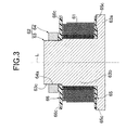
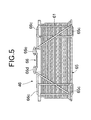
- a bobbin jig 62 for winding a conductor wire 61 into a coil shape comprises a jig body 63 and a holding member 64.
- the jig body 63 includes a disk-shaped flange part 63a and a columnar winding part 63b, and a female screw 64a of the holding member 64 is screwed onto a male screw 63c provided at a tip end of the winding part 63b.
- a first guide member 65 of a synthetic resin is fitted on the flange part 63a of the jig body 63, and comprises a disk-shaped plate which is perpendicular to the axis L.
- a second guide member 66 of a synthetic resin also comprises a disk-shaped plate which is perpendicular to the axis L the same as the first guide member 65.
- the second guide member 66 is positioned by the holding member 64 with the female screw 64a screwed onto the male screw 63c of the jig body 63 in a state in which the second guide member 66 is fitted to a step portion provided at an outer periphery of the winding part 63b of the jig body 63.
- the conductor wire 61 is wound using, as the guide, the outer peripheral surface of the winding part 63b of the jig body 63 as well as opposed surfaces between the first and second guide members 65 and 66.
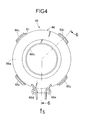
- four engaging parts 65c are formed at 90° intervals at an outer peripheral portion of the first guide member 65.
- Four engaging parts 66c are formed at 90° intervals at an outer peripheral portion of the second guide member 66, and between two engaging parts 66c and 66c among them, a start end projection 66d and a terminal end projection 66e are formed.
- a start end (winding start side) of the conductor wire 61 is first wound around the start end projection 66d of the second guide member 66, from which the conductor wire 61 is guided radially inward to the winding part 63b to be wound around the winding part 63b.
- a terminal end of the conductor wire 61 is wound into a coil shape from radially inside to outside using the winding part 63b and the first and the second guide members 65 and 66 as the guide, and is wound in a circumferential direction to be alternately engaged with the four engaging parts 65c of the first guide member 65 and the four engaging parts 66c of the second guide member 66.
- the first and second guide members 65 and 66 are biased in the direction to be close to each other.
- the terminal end (winding end) of the conductor wire 61 is wound around the terminal end projection 66e of the second guide member 66.
- a load acting on an inner diameter portion of the conductor wire 61 which is wound into the coil shape is determined by a diameter of the winding part 63b around which the conductor wire 61 is wound, a wire diameter of the conductor wire 61, the number of windings and the winding tensile force of the conductor wire 61.
- the load acting on the inner diameter portion becomes larger as the number of windings becomes larger, and a plastic deformation zone of the conductor wire 61 becomes large.
- the plastic deformation zone of the conductor wire 61 can be controlled by adjusting the diameter of the winding part 63b around which the conductor wire 61 is wound, the wire diameter of the conductor wire 61, and the number of windings and the winding tensile force of the conductor wire 61.
- the conductor wire 61 at that portion is plastically deformed by enhancing the winding tensile force of three layers of conductor wire 61 which is densely shown in FIG. 3, to thereby enhance the holding function of the coil shape.
- the holding member 64 is separated from the jig body 63, and the jig body 63 is extracted from the inner peripheral surface of the conductor wire 61.
- the synthetic resin coil cover 47 is molded on the outer peripheral surface excluding the inner peripheral surface of the coil-shaped conductor wire 61, and on an outer surfaces of the first and the second guide members 65 and 66, to thereby complete the coil assembly 43.
- the connector 48 is integrally formed therein.
- seal member 49 is disposed between the top surface of the coil cover 47 and the undersurface of the yoke 44, and a seal member 50 is disposed between the undersurface of the bobbinless coil 46 and the top surface of the fixed core 42.
- seal members 49 and 50 prevent water and dust from entering an inner space of the actuator 41 from the openings 13b and 12c formed in the actuator case 13 and the lower housing 12.
- a bearing member 51 having a thin-walled cylindrical shape is vertically slidably fitted to an inner peripheral surface of a cylindrical part 44a of the yoke 44.
- An upper flange 51a folded radially inward is formed at an upper end of the bearing member 51, and a lower flange 51b folded radially outward is formed at a lower end.
- a set spring 52 is disposed under compression between the lower flange 51b and a lower end of the cylindrical part 44a of the yoke 44.
- the lower flange 51b is pressed by a resilient force of the set spring 52 against a top surface of the fixed core 42 via an elastic body 53, so that the bearing member 51 is supported by the yoke 44.
- a substantially cylindrical movable core 54 is vertically slidably fitted onto an inner peripheral surface of the bearing member 51.
- a rod 55 extending downward from a center of the movable member 28 loosely penetrates through a center of the movable core 54, and a nut 56 is fastened to a lower end of the rod 55.
- a set spring 58 is disposed under compression between a spring seat 57 provided on a top surface of the movable core 54 and an undersurface of the movable member 28, and the movable core 54 is pressed by a resilient force of the set spring 58 against the nut 56 to be fixed.
- an undersurface of the movable core 54 and the top surface of the fixed core 42 are opposed to each other with a conical air gap g therebetween.
- the rod 55 and the nut 56 are loosely fitted in an opening 42a formed in a center of the fixed core 42, and the opening 42a is closed by a plug 60 via a seal member 59.
- An electronic control unit U to which a crank pulse sensor Sa for detecting a crank pulse outputted with rotation of a crankshaft of an engine is connected, controls energization to the actuator 41 of the active vibration isolation support system M.
- the crank pulses of the engine are outputted 24 times per rotation of the crankshaft, namely, one crank pulse is outputted at each 15° of the crank angle.
- the shape and size of the communication passage 32 and the spring constant of the first elastic body 19 are set to exhibit a low spring constant and a high damping force in the frequency region of the engine shake vibration, thereby effectively reducing the vibration transmitted from the engine to the vehicle frame.
- the actuator 41 is kept in the non-operational state in the frequency region of the engine shake vibration.
- the electronic control unit U controls energization to the bobbinless coil 46 based on the signal from the crank pulse sensor Sa in order to exhibit the vibration isolating function by operating the actuator 41 of the active vibration isolation support system M.
- the electronic control unit U first reads the crank pulse which is outputted every 15° of the crank angle from the crank pulse sensor Sa in Step S1, and calculates the time interval of the crank pulses by comparing the read crank pulse with crank pulse which is the reference (TDC signal of a specific cylinder) in Step S2.
- the electronic control unit U calculates a crank angular speed ⁇ by dividing the crank angle of 15° by the time interval of the crank pulses.
- the electronic control unit U calculates a crank angular acceleration d ⁇ /dt by differentiating the crank angular speed ⁇ with time.
- the torque Tq is 0 when it is assumed that the crankshaft rotates at a constant angular speed ⁇ , but in the expansion stroke, the angular speed ⁇ increases due to acceleration of the piston, and in the compression stroke, the angular speed ⁇ decreases due to deceleration of the piston to cause the crank angular acceleration d ⁇ /dt. Therefore, the torque Tq proportional to the crank angular acceleration d ⁇ /dt occurs.
- Step S6 the electronic control unit U determines the maximum value and the minimum value of the torques adjacent timewise.
- Step S7 the electronic control unit U calculates an amplitude at the position of the active vibration isolation support system M which supports the engine, as a difference between the maximum value and the minimum value of torque, namely, as a variation amount of torque.
- step S8 the electronic control unit U determines a duty waveform and timing (phase) of an electric current which is applied to the bobbinless coil 46 of the actuator 41.
- the bobbinless coil 46 of the actuator 41 is excited in this timing, so that the movable core 54 moves downward toward the fixed core 42 by the attraction force generated in the air gap g and the second elastic body 27 deforms downward by being pulled by the movable member 28 connected to the movable core 54 via the rod 55.
- the capacity of the second liquid chamber 31 increases, and therefore the liquid in the first liquid chamber 30, which is compressed by the load from the engine, passes through the communication hole 29a of the partition wall member 29 and flows into the second liquid chamber 31, thus reducing the load transmitted from the engine to the vehicle body frame.
- the bobbinless coil 46 of the actuator 41 is demagnetized in this timing, so that the attraction force generated in the air gap g disappears and the movable core 54 can freely move. Therefore, the second elastic body 27 which has been deformed downward restores upward with its own elastic restoring force. As a result, the capacity of the second liquid chamber 31 decreases, and therefore, the liquid in the second liquid chamber 31 passes through the communication hole 29a of the partition wall member 29 and flows into the first liquid chamber 30, thus allowing the engine to move upward with respect to the vehicle body frame.
- the first and the second guide members 65 and 66 are made to abut on opposite end surfaces in the direction of the axis L of the conductor wire 61 wound round into the coil shape, and the pair of guide members 65 and 66 are biased in the direction to be close to each other by utilizing the conductor wire 61. Therefore, it is possible to reliably maintain the shape of the bobbinless coil 46 having the conductor wire 61 which is wound round into the coil shape and which exposes its inner peripheral surface, and eliminate the need of the special biasing member to reduce the number of the components. Further, it is possible to prevent loosening of the conductor wire 61, while reducing the number of components and the cost by removing the bobbin and the tape having a bonding layer from the bobbinless coil 46. Furthermore, it is possible to reduce the inner diameter of the bobbinless coil 46 corresponding to the amount of the bobbin, thus reducing the resistance and inductance to enhance electric current responsiveness.
- the bobbinless coil 46 of the active vibration isolation support system M is shown as an example of the embodiment, but the bobbinless coil of the present invention is applicable to any other use and purpose.
- the first and the second guide members 65 and 66 which are disposed at opposite ends in the axis L direction of the conductor wire 61 wound round into the coil shape, are biased by the conductor wire 61 itself, but they can be biased by using any biasing member (a wire or a spring) instead of the conductor wire 61.
- first and second guide members 65 and 66 are biased at one end of the conductor wire 61, but they may be biased at opposite ends of the conductor wire 61.
- the method of winding the conductor wire 61 for biasing the first and second guide members 65 and 66 in the direction to be close to each other is optional.
Landscapes
- Engineering & Computer Science (AREA)
- Power Engineering (AREA)
- General Engineering & Computer Science (AREA)
- Electromagnetism (AREA)
- Physics & Mathematics (AREA)
- Mechanical Engineering (AREA)
- Manufacturing & Machinery (AREA)
- Arrangement Or Mounting Of Propulsion Units For Vehicles (AREA)
- Combined Devices Of Dampers And Springs (AREA)
- Coil Winding Methods And Apparatuses (AREA)
- Electromagnets (AREA)
- Manufacture Of Motors, Generators (AREA)
- Reciprocating, Oscillating Or Vibrating Motors (AREA)
- Coils Or Transformers For Communication (AREA)
Applications Claiming Priority (2)
| Application Number | Priority Date | Filing Date | Title |
|---|---|---|---|
| JP2005008554 | 2005-01-17 | ||
| PCT/JP2005/022620 WO2006075464A1 (ja) | 2005-01-17 | 2005-12-09 | ボビンレスコイルおよびボビンレスコイルの製造方法 |
Publications (3)
| Publication Number | Publication Date |
|---|---|
| EP1840909A1 true EP1840909A1 (de) | 2007-10-03 |
| EP1840909A4 EP1840909A4 (de) | 2008-02-13 |
| EP1840909B1 EP1840909B1 (de) | 2011-01-26 |
Family
ID=36677496
Family Applications (1)
| Application Number | Title | Priority Date | Filing Date |
|---|---|---|---|
| EP05814733A Expired - Lifetime EP1840909B1 (de) | 2005-01-17 | 2005-12-09 | Rollenlose spule und verfahren zu ihrer herstellung |
Country Status (10)
| Country | Link |
|---|---|
| US (2) | US7696848B2 (de) |
| EP (1) | EP1840909B1 (de) |
| JP (1) | JP4358238B2 (de) |
| KR (1) | KR100852925B1 (de) |
| CN (1) | CN101040352B (de) |
| CA (1) | CA2579152C (de) |
| DE (1) | DE602005026176D1 (de) |
| RU (1) | RU2340026C1 (de) |
| TW (1) | TWI291185B (de) |
| WO (1) | WO2006075464A1 (de) |
Families Citing this family (14)
| Publication number | Priority date | Publication date | Assignee | Title |
|---|---|---|---|---|
| DE102006037169A1 (de) * | 2006-08-09 | 2008-02-14 | Robert Bosch Gmbh | Verfahren zur Herstellung einer Spule, insbesondere einer Zündspule für ein Kraftfahrzeug |
| JP4980808B2 (ja) * | 2007-07-06 | 2012-07-18 | 株式会社ケーヒン | 能動型防振支持装置 |
| JP4981609B2 (ja) * | 2007-10-04 | 2012-07-25 | 株式会社ケーヒン | コイル巻線方法及びコイル巻線体 |
| JP5155678B2 (ja) * | 2008-01-25 | 2013-03-06 | 株式会社ケーヒン | コイル巻線システム |
| US8253524B2 (en) | 2007-10-04 | 2012-08-28 | Keihin Corporation | Coil winding system and method for fabricating molded coil |
| JP4966819B2 (ja) * | 2007-10-26 | 2012-07-04 | 株式会社ケーヒン | コイル巻線装置 |
| DE102008016488A1 (de) | 2008-03-31 | 2009-10-01 | Epcos Ag | Spule und Verfahren zur Herstellung einer Spule |
| JP4880659B2 (ja) * | 2008-10-31 | 2012-02-22 | 本田技研工業株式会社 | 能動型防振支持装置 |
| RU2482562C2 (ru) * | 2010-07-09 | 2013-05-20 | В & С Ворлд Ко. Лтд | Высоковольтный импульсный трансформатор без сердечника |
| DE102011005165B4 (de) * | 2011-03-07 | 2015-03-26 | Vacuumschmelze Gmbh & Co. Kg | Spule mit einer Wicklung, die eine Durchmesserreduzierung aufweist, Stromsensor mit einer solchen Spule und Verfahren zur Herstellung einer solchen Spule und eines solchen Stromsensors |
| JP6126343B2 (ja) * | 2012-09-14 | 2017-05-10 | 株式会社ケーヒン | コイル装置 |
| JP6002049B2 (ja) * | 2013-01-16 | 2016-10-05 | 本田技研工業株式会社 | 能動型防振支持装置の制御装置 |
| RU2605769C1 (ru) * | 2015-08-26 | 2016-12-27 | Закрытое Акционерное Общество "Импульс" | Способ изготовления бескаркасной катушки индуктивности и оправка для ее изготовления |
| JP7186138B2 (ja) * | 2019-06-26 | 2022-12-08 | 日立Astemo株式会社 | ソレノイドコイル |
Family Cites Families (29)
| Publication number | Priority date | Publication date | Assignee | Title |
|---|---|---|---|---|
| US1893262A (en) * | 1930-11-20 | 1933-01-03 | Herbert F Apple | Reenforced electrical coil |
| GB756021A (en) * | 1951-05-04 | 1956-08-29 | Henleys Telegraph Works Co Ltd | Improvements in or relating to bobbins for coil winders |
| GB1273347A (en) * | 1968-06-26 | 1972-05-10 | Dowty Technical Dev Ltd | Electrical moving coil device |
| JPS5933797B2 (ja) | 1977-03-02 | 1984-08-17 | 株式会社日立製作所 | 弁駆動機構 |
| JPS584050B2 (ja) | 1980-06-10 | 1983-01-24 | 第一工業製薬株式会社 | 変性ポリイソシアヌレ−トフォ−ムの製造方法 |
| JPS5851502A (ja) | 1981-09-22 | 1983-03-26 | Sony Corp | 多層コイル及びその巻線方法 |
| JPS58106929A (ja) | 1981-12-18 | 1983-06-25 | Yamauchi Shunji | 秘話通信方法及び装置 |
| JPS58106929U (ja) * | 1982-01-13 | 1983-07-21 | 三菱電機株式会社 | 空心リアクトル |
| JPH0815376B2 (ja) * | 1984-11-09 | 1996-02-14 | 株式会社北斗製作所 | 自己融着電線使用による多層空芯コイルの巻線方法及び巻線装置 |
| BE902077A (nl) * | 1985-04-01 | 1985-07-31 | Bekaert S A Nv Nv | Bobijn |
| SU1758686A1 (ru) * | 1989-02-20 | 1992-08-30 | Особое Конструкторское Бюро При Николаевском Трансформаторном Заводе Им.Ленинского Комсомола | Оправка дл намотки бескаркасных катушек |
| DE4106589C2 (de) | 1991-03-01 | 1997-04-24 | Wacker Siltronic Halbleitermat | Kontinuierliches Nachchargierverfahren mit flüssigem Silicium beim Tiegelziehen nach Czochralski |
| JPH05266506A (ja) * | 1992-03-19 | 1993-10-15 | Sony Corp | 2軸アクチュエータ |
| JPH07220964A (ja) | 1994-02-03 | 1995-08-18 | Murata Mfg Co Ltd | 高圧トランス |
| RU2065631C1 (ru) * | 1994-05-20 | 1996-08-20 | Хабузов Василий Арсеньевич | Трансформатор и способ его изготовления |
| JP3562052B2 (ja) * | 1995-08-17 | 2004-09-08 | 株式会社デンソー | マグネットスイッチのソレノイド製造方法 |
| AU2321997A (en) * | 1996-03-06 | 1997-09-22 | Kelsey-Hayes Company | Bobbinless solenoid coil |
| AU4232397A (en) * | 1996-08-20 | 1998-03-06 | Kelsey-Hayes Company | Solenoid coil structure and interconnection |
| DE19640659B4 (de) * | 1996-10-02 | 2005-02-24 | Fev Motorentechnik Gmbh | Verfahren zur Betätigung eines elektromagnetischen Aktuators mit Beeinflussung des Spulenstroms während der Ankerbewegung |
| JPH10172823A (ja) | 1996-12-11 | 1998-06-26 | Totoku Electric Co Ltd | フッ素樹脂絶縁コイルおよびその製造方法ならびにフッ素樹脂絶縁電線およびその製造方法 |
| US6124775A (en) * | 1997-03-05 | 2000-09-26 | Kelsey-Hayes Company | Bobbinless solenoid coil |
| US5984210A (en) * | 1997-11-04 | 1999-11-16 | Caterpillar Inc. | Fuel injector utilizing a solenoid having complementarily-shaped dual armatures |
| DE19919396A1 (de) * | 1998-04-28 | 1999-11-04 | Kelsey Hayes Co | Spulenträgerlose Elektromagnetspule |
| KR100363154B1 (ko) * | 1998-08-13 | 2003-03-19 | 삼성전자 주식회사 | 광픽업의액츄에이터및그에따른구동코일권선방법 |
| TW533655B (en) | 2001-08-20 | 2003-05-21 | Sunonwealth Electr Mach Ind Co | DC motor and its coil winding method |
| JP2003100526A (ja) | 2001-09-21 | 2003-04-04 | Hitachi Media Electoronics Co Ltd | トランス |
| TW523155U (en) | 2001-12-13 | 2003-03-01 | Jr-Chiang Jou | Insulated winding structure of ring type coil |
| JP4255741B2 (ja) * | 2003-04-24 | 2009-04-15 | 本田技研工業株式会社 | 電磁コイルアセンブリ及び電磁アクチュエータ |
| JP4815300B2 (ja) * | 2006-07-31 | 2011-11-16 | 日本電産サンキョー株式会社 | ステッピングモータのステータコアの製造方法並びにそのステッピングモータ |
-
2005
- 2005-12-09 CA CA2579152A patent/CA2579152C/en not_active Expired - Fee Related
- 2005-12-09 CN CN2005800346579A patent/CN101040352B/zh not_active Expired - Fee Related
- 2005-12-09 RU RU2007114268/09A patent/RU2340026C1/ru not_active IP Right Cessation
- 2005-12-09 DE DE602005026176T patent/DE602005026176D1/de not_active Expired - Lifetime
- 2005-12-09 WO PCT/JP2005/022620 patent/WO2006075464A1/ja not_active Ceased
- 2005-12-09 JP JP2006552860A patent/JP4358238B2/ja not_active Expired - Fee Related
- 2005-12-09 KR KR1020077008589A patent/KR100852925B1/ko not_active Expired - Fee Related
- 2005-12-09 TW TW094143737A patent/TWI291185B/zh not_active IP Right Cessation
- 2005-12-09 EP EP05814733A patent/EP1840909B1/de not_active Expired - Lifetime
- 2005-12-20 US US11/313,276 patent/US7696848B2/en active Active
-
2010
- 2010-03-26 US US12/732,673 patent/US7834734B2/en not_active Expired - Lifetime
Also Published As
| Publication number | Publication date |
|---|---|
| EP1840909A4 (de) | 2008-02-13 |
| CN101040352A (zh) | 2007-09-19 |
| US7834734B2 (en) | 2010-11-16 |
| KR100852925B1 (ko) | 2008-08-19 |
| US20100175244A1 (en) | 2010-07-15 |
| CN101040352B (zh) | 2012-05-30 |
| TWI291185B (en) | 2007-12-11 |
| RU2340026C1 (ru) | 2008-11-27 |
| EP1840909B1 (de) | 2011-01-26 |
| US20060156536A1 (en) | 2006-07-20 |
| US7696848B2 (en) | 2010-04-13 |
| KR20070069166A (ko) | 2007-07-02 |
| CA2579152A1 (en) | 2006-07-20 |
| CA2579152C (en) | 2011-07-19 |
| DE602005026176D1 (de) | 2011-03-10 |
| JP4358238B2 (ja) | 2009-11-04 |
| TW200632954A (en) | 2006-09-16 |
| WO2006075464A1 (ja) | 2006-07-20 |
| JPWO2006075464A1 (ja) | 2008-06-12 |
Similar Documents
| Publication | Publication Date | Title |
|---|---|---|
| US7834734B2 (en) | Bobbinless coil and method of manufacturing the same | |
| US6641120B2 (en) | Method for controlling drive of actuator of active vibration isolation support system | |
| US20080136074A1 (en) | Active vibration isolation support system | |
| JP4980808B2 (ja) | 能動型防振支持装置 | |
| JP4875363B2 (ja) | 能動型防振支持装置 | |
| JP4638303B2 (ja) | ボビンレスコイル組立体およびボビンレスコイル組立体の製造方法 | |
| JP4319132B2 (ja) | ボビンレスコイルの製造方法 | |
| US20050006830A1 (en) | Actuator drive control device for active vibration isolation support system, and method of using the same | |
| JP2006156710A5 (de) | ||
| US7192014B2 (en) | Active vibration isolation support system | |
| JP2006156872A (ja) | コイル組立体の製造方法 | |
| JP4648131B2 (ja) | 能動型防振支持装置 | |
| JP4880659B2 (ja) | 能動型防振支持装置 | |
| JP4767513B2 (ja) | ボビンレスコイル | |
| JP5147966B2 (ja) | ボビンレスコイル及びボビンレスコイルの製造方法 | |
| JP4767720B2 (ja) | 能動型防振支持装置 | |
| JP2006196837A (ja) | コイルの製造方法 | |
| JP2007321906A (ja) | ソレノイド型アクチュエータおよび能動型防振支持装置 | |
| JP2005256931A (ja) | 能動型防振支持装置 | |
| JP2006002831A (ja) | 能動型防振支持装置 | |
| JP2005207505A (ja) | 能動型液封入式防振装置 | |
| JP2006057751A (ja) | エンジンの防振支持装置 |
Legal Events
| Date | Code | Title | Description |
|---|---|---|---|
| PUAI | Public reference made under article 153(3) epc to a published international application that has entered the european phase |
Free format text: ORIGINAL CODE: 0009012 |
|
| 17P | Request for examination filed |
Effective date: 20070308 |
|
| AK | Designated contracting states |
Kind code of ref document: A1 Designated state(s): DE FR GB |
|
| A4 | Supplementary search report drawn up and despatched |
Effective date: 20080114 |
|
| RIC1 | Information provided on ipc code assigned before grant |
Ipc: H01F 27/30 20060101ALI20080108BHEP Ipc: H01F 7/16 20060101ALN20080108BHEP Ipc: H01F 27/28 20060101ALI20080108BHEP Ipc: F16F 13/26 20060101ALI20080108BHEP Ipc: H01F 41/04 20060101ALI20080108BHEP Ipc: H01F 41/06 20060101ALI20080108BHEP Ipc: H01F 5/00 20060101AFI20060725BHEP Ipc: B06B 1/04 20060101ALI20080108BHEP |
|
| 17Q | First examination report despatched |
Effective date: 20080320 |
|
| DAX | Request for extension of the european patent (deleted) | ||
| RBV | Designated contracting states (corrected) |
Designated state(s): DE FR GB |
|
| GRAP | Despatch of communication of intention to grant a patent |
Free format text: ORIGINAL CODE: EPIDOSNIGR1 |
|
| GRAS | Grant fee paid |
Free format text: ORIGINAL CODE: EPIDOSNIGR3 |
|
| GRAA | (expected) grant |
Free format text: ORIGINAL CODE: 0009210 |
|
| AK | Designated contracting states |
Kind code of ref document: B1 Designated state(s): DE FR GB |
|
| REG | Reference to a national code |
Ref country code: GB Ref legal event code: FG4D |
|
| REF | Corresponds to: |
Ref document number: 602005026176 Country of ref document: DE Date of ref document: 20110310 Kind code of ref document: P |
|
| REG | Reference to a national code |
Ref country code: DE Ref legal event code: R096 Ref document number: 602005026176 Country of ref document: DE Effective date: 20110310 |
|
| PLBE | No opposition filed within time limit |
Free format text: ORIGINAL CODE: 0009261 |
|
| STAA | Information on the status of an ep patent application or granted ep patent |
Free format text: STATUS: NO OPPOSITION FILED WITHIN TIME LIMIT |
|
| 26N | No opposition filed |
Effective date: 20111027 |
|
| REG | Reference to a national code |
Ref country code: DE Ref legal event code: R097 Ref document number: 602005026176 Country of ref document: DE Effective date: 20111027 |
|
| REG | Reference to a national code |
Ref country code: DE Ref legal event code: R084 Ref document number: 602005026176 Country of ref document: DE |
|
| REG | Reference to a national code |
Ref country code: GB Ref legal event code: 746 Effective date: 20140813 |
|
| REG | Reference to a national code |
Ref country code: DE Ref legal event code: R084 Ref document number: 602005026176 Country of ref document: DE Effective date: 20140821 |
|
| REG | Reference to a national code |
Ref country code: FR Ref legal event code: PLFP Year of fee payment: 11 |
|
| REG | Reference to a national code |
Ref country code: FR Ref legal event code: PLFP Year of fee payment: 12 |
|
| PGFP | Annual fee paid to national office [announced via postgrant information from national office to epo] |
Ref country code: GB Payment date: 20161207 Year of fee payment: 12 Ref country code: FR Payment date: 20161111 Year of fee payment: 12 |
|
| GBPC | Gb: european patent ceased through non-payment of renewal fee |
Effective date: 20171209 |
|
| REG | Reference to a national code |
Ref country code: FR Ref legal event code: ST Effective date: 20180831 |
|
| PG25 | Lapsed in a contracting state [announced via postgrant information from national office to epo] |
Ref country code: FR Free format text: LAPSE BECAUSE OF NON-PAYMENT OF DUE FEES Effective date: 20180102 |
|
| PG25 | Lapsed in a contracting state [announced via postgrant information from national office to epo] |
Ref country code: GB Free format text: LAPSE BECAUSE OF NON-PAYMENT OF DUE FEES Effective date: 20171209 |
|
| PGFP | Annual fee paid to national office [announced via postgrant information from national office to epo] |
Ref country code: DE Payment date: 20211012 Year of fee payment: 17 |
|
| REG | Reference to a national code |
Ref country code: DE Ref legal event code: R119 Ref document number: 602005026176 Country of ref document: DE |
|
| PG25 | Lapsed in a contracting state [announced via postgrant information from national office to epo] |
Ref country code: DE Free format text: LAPSE BECAUSE OF NON-PAYMENT OF DUE FEES Effective date: 20230701 |