EP1841360B1 - Tropfendetektorsystem - Google Patents
Tropfendetektorsystem Download PDFInfo
- Publication number
- EP1841360B1 EP1841360B1 EP06700595A EP06700595A EP1841360B1 EP 1841360 B1 EP1841360 B1 EP 1841360B1 EP 06700595 A EP06700595 A EP 06700595A EP 06700595 A EP06700595 A EP 06700595A EP 1841360 B1 EP1841360 B1 EP 1841360B1
- Authority
- EP
- European Patent Office
- Prior art keywords
- pulses
- optical
- drop
- detection system
- light beam
- Prior art date
- Legal status (The legal status is an assumption and is not a legal conclusion. Google has not performed a legal analysis and makes no representation as to the accuracy of the status listed.)
- Expired - Lifetime
Links
Images


Classifications
-
- A—HUMAN NECESSITIES
- A61—MEDICAL OR VETERINARY SCIENCE; HYGIENE
- A61M—DEVICES FOR INTRODUCING MEDIA INTO, OR ONTO, THE BODY; DEVICES FOR TRANSDUCING BODY MEDIA OR FOR TAKING MEDIA FROM THE BODY; DEVICES FOR PRODUCING OR ENDING SLEEP OR STUPOR
- A61M5/00—Devices for bringing media into the body in a subcutaneous, intra-vascular or intramuscular way; Accessories therefor, e.g. filling or cleaning devices, arm-rests
- A61M5/14—Infusion devices, e.g. infusing by gravity; Blood infusion; Accessories therefor
- A61M5/168—Means for controlling media flow to the body or for metering media to the body, e.g. drip meters, counters ; Monitoring media flow to the body
- A61M5/16886—Means for controlling media flow to the body or for metering media to the body, e.g. drip meters, counters ; Monitoring media flow to the body for measuring fluid flow rate, i.e. flowmeters
- A61M5/1689—Drip counters
Definitions
- the present invention relates to low-flow metering of fluids.
- the invention provides an optical system for measuring low flow-rates of a fluid that passes a measuring point in the form of discrete drops.
- the present invention achieves the above objectives by providing an optical drop detection system for a low-flow metering device of the type having a drop generator, said system comprising at least one optical transmitter which produces a plurality of light beam pulses of microsecond duration and at millisecond intervals, and at least one optical receiver positioned to register receipt of said light pulses transmitted through the path of drops generated by said drop generator, and to record the number of pulses which hit a given drop and which do not register on said receiver, the frequency and strength of said pulses being calibrated so that a single drop is impinged upon by a plurality of pulses and further comprising automatic feed-back means for adjusting the parameters of interaction between said at least one optical transmitter and said at least one optical receiver to produce and maintain a predetermined minimum and a predetermined maximum number of hits per drop.
- an optical drop detection system wherein said optical transmitter produces a plurality of light beam pulses, preferably IR light beam pulses.
- an optical drop detection system wherein said pulses are calibrated so that a single drop is impinged upon by at least 1, or preferably at least 3 pulses.
- said pulses are calibrated so that a single drop is impinged upon by up to 20 pulses, preferably by up to 8 pulses.
- the interval between said pulses is between 0.2 and 50 milliseconds, the most preferred range being between 1 and 10 milliseconds.
- said change in the intensity of the transmitted light beam pulses is effected by use of a variable resistor or amplifier.
- said change in the intensity of the transmitted light beam pulses is effected by varying a connection between said at least one optical transmitter and a plurality of amplifiers.
- Another embodiment provides a system wherein the parameters of interaction between said at least one optical transmitter and said at least one optical receiver are varied by changing the frequency of the transmitted light beam pulses.
- novel device of the present invention need be calibrated only once, unless of course some change occurs in the fluid being metered. Apart from occasional cleaning, if needed, of the optically active faces, the device is maintenance free.
- the device can advantageously be used with the drop generator disclosed in US 6,640,649 B1 .
- the electrodes are replaced by a light emitter and a light receiver, which light receiver is attached outside the transparent walls of the housing chamber opposite the emitter, which is also positioned outside the transparent walls of the housing chamber.
- An electronics control and display housing sends power pulses to the light emitter and meters the corresponding electric output of the receiver. Lack of such output indicates that an interposing droplet of fluid has deflected the light beam from reaching the receiver.
- pulse frequency is much faster than droplet generation, the electronics easily distinguishes between a droplet, a gap, and a succeeding droplet.
- the data generated is electronically converted to flow rate and displayed on a screen. If needed, results can also be printed on paper tape.
- FIG. 1 An optical drop detection system 10, for a low-flow metering device.
- the device includes a drop generator.
- the drop generator seen in the figure has been fully described in US 6,640,649 B1 .
- the drop generator is not the central subject of the present invention, components thereof are presented in FIG.1 , for a better understanding of the present invention as it would be applied to such a drop generator, wherein the main components of said drop generator are as follows: first chamber 12 and second chamber 17 having outer transparent walls 4 and 6, droplets 18, orifice 19, overflow and gas pressure equalizer 21, porous substance 24, and electronics 30.
- the present invention may however be applied to other types of drop generators.
- the system shown 10 has an optical transmitter 26, positioned outside of transparent wall 4 of second chamber 17, which produces light beam pulses 28, of microsecond duration and at millisecond intervals.
- the light beam pulses 28 are of IR frequency.
- An optical receiver 32 is positioned outside of transparent wall 6 of second chamber 17, opposite optical transmitter 26, to register receipt of the light pulses 28, unless it is disturbed by the passage of droplets 18 produced by the drop generator.
- the electronics 30 record the number of pulses that hit a given drop and due to deflection by a passing drop do not register on the receiver 32.
- the frequency and intensity of the light beam pulses 28 are calibrated so that a single drop is impinged upon by a plurality of pulses.
- the optical transmitter 26 is pulsed with relatively high power but for extremely short periods of time.
- the optical receiver 32 sees the generated light beam and registers that it has in fact received said light beam. Thus the optical receiver 32 expects to see the light beam pulse 28 every time a beam is transmitted.
- the arrangement is such that when the optical receiver 32 registers receipt of a light pulse 28, it registers a "miss”. If however, it does not register receipt of an expected light beam pulse, it registers a "hit".
- a falling drop 18, that passes through the beam 28, does not allow every light beam pulse to be registered by the optical receiver 32.
- not every light beam pulse 28, that impinges on a drop is deflected. There are beams that go through the drop, depending on the angle of impingement and the strength of the light beam pulse.
- the light beam pulse can be so strong that it will always be registered and the passage of a drop will not be detected, thus registering a miss, or the light beam pulse can be so weak that more hits are detected than actually occur, due to other circumstances as discussed hereinafter.
- the arrangement is such that if the light beam pulse 28, hits a drop 18 at a certain critical angle, then it is deflected and the beam will not be detected by the optical receiver 32, which is registered as a "hit”. If the light beam pulse impinges on the drop at angles other than the predetermined critical angle, then the light beam will pass through the drop, will be received by the optical receiver 32, and registered as a "miss” rather than a "hit”.
- each drop 18 that falls cuts the light pulse beam 28 in different ways depending on the strength of the pulse beam, the frequency of the pulses, etc.,
- an arbitrary representative number of drops from between e.g. 3-30 for calibrating a predetermined minimum and maximum number of hits for the particular system.
- a first drop may be impinged upon by a plurality of pulses 28, resulting in the optical receiver 32 recording 5 hits, while the next drop 18 is also impinged upon by a plurality of pulses 28, but because of the timing of the passage of the drop relative to the timing of the pulses, the optical receiver 32 only records 3 hits.
- the following drop could result in the recording of, e.g., 4 hits.
- the minimum number of hits for a drop is not recorded and registered by optical receiver 32, it means that at least one drop was "missed", which could indicate that the strength of the light beam pulse 28 is excessive which would also require recalibration according to the present invention.
- the present invention provides a feedback loop whereby the strength of the light beam pulses may be adjusted according to actual registration of receipt of the minimum and/or maximum hits.
- a weak beam is detected by the recording of a higher number of maximum hits than that precalibrated for the system, and a strong beam is detected by a lower number of minimum hits than that precalibrated for the system, as described hereinbefore.
- the system electronics 30 provides for automatic feed-back means for adjusting the parameters of interaction, such as the present pulse rate 42 and the desired pulse rate 44 of the optical transmitter 26.
- the optical receiver 32 seen in FIG. 1 is to produce and maintain a predetermined minimum and a predetermined maximum number of hits per drop.
- a feedback line informs the comparator 22 of the present rate and the comparator 22 then signals the pulse rate control 14 to reduce the difference between the new and desired value.
- a pulse beam rate control 14 increases/decreases the pulse rate and intensity strength to conform to a desired number of hits per droplet.
- the display screen shows the calculated flow rate 34, total accumulated flow 36, starting time 38, elapsed time 40, and other data as needed.
- FIG. 3 represents an optical drop detection system 46 wherein two optical transmitters 26 produce a plurality of IR light beam pulses 28, which are received by three closely-spaced optical receivers 32. Droplets 18 fall between the transmitters 26 and the receivers 32 and deflect the light beam pulses 28, the results being processed electronically to calculate the flow rate 34 seen in FIG. 1 .
- FIG. 4 there is seen a graphical representation of a drop detection system wherein the light beam pulses 28 are calibrated so that a single drop 48 is impinged upon by at least 2 pulses and preferably by at least 3 pulses and at most by 8 pulses.
- the hits are dependent on the strength of the light pulses 28 passing through or being stopped by the drops 48.
- a dark interval 56 between pulses is between 0.2 and 50 milliseconds, and preferably the interval between the pulses is between 1 and 10 milliseconds.
- FIG. 5 there is seen a circuit of a further optical drop detection system 50 wherein the parameters of interaction between the optical transmitter 26 and the optical receiver 32, seen in FIG. 1 , are varied by changing the intensity of the transmitted light beam pulses 28.
- the change in the intensity of the transmitted light beam pulses 28 is effected by a variable resistor 52 or amplifier (not shown).
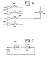
- FIG. 6 is a circuit diagram referring to an embodiment wherein the change in the intensity of the transmitted light beam pulses 28 is effected by varying a connection between the optical transmitter 26 and a plurality of resistors 58 (R1, R2, R3, R4) of different values and amplifiers 60.
- FIG. 7 illustrates a detail of an optical drop detection system wherein the parameters of interaction between the optical transmitter 26 and the optical receiver 32 (seen in FIG. 1 ) are varied by changing the frequency of the transmitted light beam pulses 28 by means of a frequency controller 62
Landscapes
- Health & Medical Sciences (AREA)
- Animal Behavior & Ethology (AREA)
- Public Health (AREA)
- Vascular Medicine (AREA)
- Engineering & Computer Science (AREA)
- Anesthesiology (AREA)
- Biomedical Technology (AREA)
- Heart & Thoracic Surgery (AREA)
- Hematology (AREA)
- Life Sciences & Earth Sciences (AREA)
- Physics & Mathematics (AREA)
- Fluid Mechanics (AREA)
- Veterinary Medicine (AREA)
- General Health & Medical Sciences (AREA)
- Measuring Volume Flow (AREA)
- Investigating Or Analysing Materials By Optical Means (AREA)
- Geophysics And Detection Of Objects (AREA)
- Photometry And Measurement Of Optical Pulse Characteristics (AREA)
- Infusion, Injection, And Reservoir Apparatuses (AREA)
- Measurement Of Velocity Or Position Using Acoustic Or Ultrasonic Waves (AREA)
- Arrangements For Transmission Of Measured Signals (AREA)
- Measurement Of Radiation (AREA)
Claims (13)
- Optisches Tropfenerfassungssystem (10) für ein Niederfluss-Durchflussmessgerät vom einen Tropfengenerator (12, 17, 21, 24) aufweisenden Typ, wobei das System wenigstens einen optischen Sender (26), der dazu geeignet ist, eine Vielzahl von Lichtstrahlimpulsen (28) von Mikrosekundendauer und in Millisekunden-Intervallen zu erzeugen, und wenigstens einen optischen Empfänger (32) enthält, der so positioniert ist, dass er den Empfang der Lichtimpulse (28), die durch die Bahn der vom Tropfengenerator erzeugten Tropfen (18) hindurch übertragen werden, registriert und die Zahl der Impulse aufzeichnet, die auf einen gegebenen Tropfen treffen und die am Empfänger nicht registriert werden, wobei die Frequenz und die Stärke der Impulse so kalibriert sind, dass ein einzelner Tropfen einer Vielzahl von Impulsen getroffen wird, dadurch gekennzeichnet, dass es darüber hinaus ein automatisches Rückkopplungsmittel (30) zum Einstellen der Parameter der Wechselwirkung zwischen dem wenigstens einen optischen Sender und dem wenigstens einen optischen Empfänger enthält, um eine bestimmte minimale und eine bestimmte maximale Zahl an Treffern pro Tropfen zu erzeugen und beizubehalten.
- Optisches Tropfenerfassungssystem nach Anspruch 1, wobei der optische Sender dazu geeignet ist, eine Vielzahl von Lichtstrahlimpulsen zu erzeugen.
- Optisches Tropfenerfassungssystem nach Anspruch 1, wobei die Impulse so kalibriert sind, dass ein einzelner Tropfen von wenigstens einem Impuls getroffen wird.
- Optisches Tropfenerfassungssystem nach Anspruch 1, wobei die Impulse so kalibriert sind, dass ein einzelner Tropfen von wenigstens drei Impulsen getroffen wird.
- Optisches Tropfenerfassungssystem nach Anspruch 1, wobei die Impulse so kalibriert sind, dass ein einzelner Tropfen von bis zu 8 Impulsen getroffen wird.
- Optisches Tropfenerfassungssystem nach Anspruch 1, wobei die Impulse so kalibriert sind, dass ein einzelner Tropfen von bis zu 20 Impulsen getroffen wird.
- Optisches Tropfenerfassungssystem nach Anspruch 1, wobei das Intervall zwischen den Impulsen zwischen 0,2 und 50 Millisekunden liegt.
- Optisches Tropfenerfassungssystem nach Anspruch 1, wobei das Intervall zwischen den Impulsen zwischen 1 und 10 Millisekunden liegt.
- Optisches Tropfenerfassungssystem nach Anspruch 1, wobei die Parameter der Wechselwirkung zwischen dem wenigstens einen optischen Sender und dem wenigstens einen optischen Empfänger durch Verändern der Stärke der übertragenen Lichtstrahlimpulse variiert werden.
- Optisches Tropfenerfassungssystem nach Anspruch 9, wobei die Veränderung der Stärke der übertragenen Lichtstrahlimpulse durch einen variablen Widerstand oder Verstärker bewirkt wird.
- Optisches Tropfenerfassungssystem nach Anspruch 9, wobei die Veränderung der Stärke der übertragenen Lichtstrahlimpulse durch Variieren einer Verbindung zwischen dem wenigstens einen optischen Sender und einer Vielzahl von Widerständen und Verstärkern bewirkt wird.
- Optisches Tropfenerfassungssystem nach Anspruch 1, wobei die Parameter der Wechselwirkung zwischen dem wenigstens einen optischen Sender und dem wenigstens einen optischen Empfänger durch Verändern der Frequenz der übertragenen Lichtstrahlimpulse variiert werden.
- Optisches Tropfenerfassungssystem nach Anspruch 1, wobei der optische Sender dazu geeignet ist, eine Vielzahl von IR-Lichtstrahlimpulsen zu erzeugen.
Applications Claiming Priority (2)
| Application Number | Priority Date | Filing Date | Title |
|---|---|---|---|
| IL166400A IL166400A (en) | 2005-01-20 | 2005-01-20 | Optical drop detection system |
| PCT/IL2006/000065 WO2006077578A1 (en) | 2005-01-20 | 2006-01-17 | Drop detector system |
Publications (2)
| Publication Number | Publication Date |
|---|---|
| EP1841360A1 EP1841360A1 (de) | 2007-10-10 |
| EP1841360B1 true EP1841360B1 (de) | 2009-11-04 |
Family
ID=36178202
Family Applications (1)
| Application Number | Title | Priority Date | Filing Date |
|---|---|---|---|
| EP06700595A Expired - Lifetime EP1841360B1 (de) | 2005-01-20 | 2006-01-17 | Tropfendetektorsystem |
Country Status (12)
| Country | Link |
|---|---|
| US (2) | US7763877B2 (de) |
| EP (1) | EP1841360B1 (de) |
| JP (1) | JP4981685B2 (de) |
| CN (2) | CN101920051B (de) |
| AT (1) | ATE447422T1 (de) |
| AU (1) | AU2006207210B2 (de) |
| BR (1) | BRPI0606254A2 (de) |
| CA (1) | CA2611473C (de) |
| DE (1) | DE602006010173D1 (de) |
| ES (1) | ES2335127T3 (de) |
| IL (1) | IL166400A (de) |
| WO (1) | WO2006077578A1 (de) |
Families Citing this family (63)
| Publication number | Priority date | Publication date | Assignee | Title |
|---|---|---|---|---|
| US8663128B2 (en) | 2006-11-14 | 2014-03-04 | Flowsense Ltd. | Diagnostic method and apparatus |
| JP5183311B2 (ja) * | 2008-06-12 | 2013-04-17 | リコーエレメックス株式会社 | 液吐出不良検出装置、およびインクジェット記録装置 |
| US9074920B2 (en) * | 2009-06-03 | 2015-07-07 | Biometrix Ltd. | Apparatus and method for bedside collection of body fluids and automatic volume level monitoring |
| US9151646B2 (en) | 2011-12-21 | 2015-10-06 | Deka Products Limited Partnership | System, method, and apparatus for monitoring, regulating, or controlling fluid flow |
| US9476825B2 (en) | 2010-10-19 | 2016-10-25 | Baxter International Inc. | Optical imaging system with multiple imaging channel optical sensing |
| CN102269611B (zh) * | 2011-01-22 | 2012-08-22 | 宜昌市力天电气有限责任公司 | 防爆流量监测仪 |
| JP5849629B2 (ja) * | 2011-11-14 | 2016-01-27 | セイコーエプソン株式会社 | 液滴検出装置 |
| US9372486B2 (en) | 2011-12-21 | 2016-06-21 | Deka Products Limited Partnership | System, method, and apparatus for monitoring, regulating, or controlling fluid flow |
| US9724466B2 (en) | 2011-12-21 | 2017-08-08 | Deka Products Limited Partnership | Flow meter |
| US10488848B2 (en) | 2011-12-21 | 2019-11-26 | Deka Products Limited Partnership | System, method, and apparatus for monitoring, regulating, or controlling fluid flow |
| US9746094B2 (en) | 2011-12-21 | 2017-08-29 | Deka Products Limited Partnership | Flow meter having a background pattern with first and second portions |
| US10228683B2 (en) | 2011-12-21 | 2019-03-12 | Deka Products Limited Partnership | System, method, and apparatus for monitoring, regulating, or controlling fluid flow |
| US9435455B2 (en) | 2011-12-21 | 2016-09-06 | Deka Products Limited Partnership | System, method, and apparatus for monitoring, regulating, or controlling fluid flow |
| US9746093B2 (en) | 2011-12-21 | 2017-08-29 | Deka Products Limited Partnership | Flow meter and related system and apparatus |
| US9759343B2 (en) | 2012-12-21 | 2017-09-12 | Deka Products Limited Partnership | Flow meter using a dynamic background image |
| CN103054589A (zh) * | 2013-01-31 | 2013-04-24 | 科迈(常州)电子有限公司 | 尿流量动态监测系统及其监测方法 |
| AU2014243951B2 (en) * | 2013-03-14 | 2018-12-06 | Baxter Healthcare Sa | Optical imaging system with multiple imaging channel optical sensing |
| USD745661S1 (en) | 2013-11-06 | 2015-12-15 | Deka Products Limited Partnership | Apparatus to control fluid flow through a tube |
| USD751690S1 (en) | 2013-11-06 | 2016-03-15 | Deka Products Limited Partnership | Apparatus to control fluid flow through a tube |
| USD752209S1 (en) | 2013-11-06 | 2016-03-22 | Deka Products Limited Partnership | Apparatus to control fluid flow through a tube |
| USD751689S1 (en) | 2013-11-06 | 2016-03-15 | Deka Products Limited Partnership | Apparatus to control fluid flow through a tube |
| USD749206S1 (en) | 2013-11-06 | 2016-02-09 | Deka Products Limited Partnership | Apparatus to control fluid flow through a tube |
| DE102014104996A1 (de) * | 2014-04-08 | 2015-10-08 | Marco Systemanalyse Und Entwicklung Gmbh | Dosierventil |
| CN104019991B (zh) * | 2014-06-16 | 2016-04-27 | 西北工业大学 | 液滴与固体板斜碰撞试验装置 |
| US9986945B2 (en) | 2014-07-31 | 2018-06-05 | Regents Of The University Of Minnesota | Devices, systems, and methods for obtaining and analyzing urine flow rate data using acoustics and software |
| US10576202B2 (en) | 2014-11-12 | 2020-03-03 | The General Hospital Corporation | Flow rate measurement and control of infusion devices |
| US9642967B2 (en) | 2014-11-18 | 2017-05-09 | Hill-Rom Services, Inc. | Catheter monitor integration with patient support, hygiene and healthcare communication systems |
| CA3170896A1 (en) | 2015-04-29 | 2016-11-03 | Climate Llc | Systems, methods, and devices for monitoring weather and field conditions |
| US11555945B2 (en) | 2015-04-29 | 2023-01-17 | Climate Llc | Systems, methods, and devices for monitoring weather and field conditions |
| CA2993992A1 (en) | 2015-07-31 | 2017-02-09 | Medivance Incorporated | Urine output collection and monitoring system |
| WO2017043623A1 (ja) * | 2015-09-09 | 2017-03-16 | 株式会社村田製作所 | 滴下検出装置 |
| USD905848S1 (en) | 2016-01-28 | 2020-12-22 | Deka Products Limited Partnership | Apparatus to control fluid flow through a tube |
| EP4335471A3 (de) | 2016-01-28 | 2024-08-21 | DEKA Products Limited Partnership | Vorrichtung zur überwachung, regelung oder steuerung eines fluidstroms |
| USD854145S1 (en) | 2016-05-25 | 2019-07-16 | Deka Products Limited Partnership | Apparatus to control fluid flow through a tube |
| DE102016215240B3 (de) * | 2016-08-16 | 2017-10-12 | Fraunhofer-Gesellschaft zur Förderung der angewandten Forschung e.V. | Mikrodosiereinrichtung und automatisches Mikrodosierverfahren |
| EP3532852B1 (de) * | 2016-10-28 | 2022-06-08 | Becton, Dickinson and Company | Verifizierungssensor für positive ausgabe |
| EP3338832A1 (de) * | 2016-12-23 | 2018-06-27 | Sanofi-Aventis Deutschland GmbH | Medikamentenverabreichungsvorrichtung |
| US11617568B2 (en) | 2016-12-29 | 2023-04-04 | Jay K. Joshi | Fluid output measurement device and method |
| WO2019226697A1 (en) | 2018-05-22 | 2019-11-28 | C.R. Bard, Inc. | Catheterization system and methods for use thereof |
| US11911160B2 (en) | 2018-08-10 | 2024-02-27 | C. R. Bard, Inc. | Automated urine output measurement systems and methods thereof |
| CN109224142A (zh) * | 2018-08-23 | 2019-01-18 | 北京大学第医院 | 一种引流流速监测装置 |
| CN109568102B (zh) * | 2018-12-04 | 2021-01-12 | 日照市中医医院 | 一种产后智能康复装置 |
| KR20200134707A (ko) | 2019-05-23 | 2020-12-02 | 한국타이어앤테크놀로지 주식회사 | 타이어 트레드의 고무조성물 및 이를 이용하여 제조된 타이어 |
| USD964563S1 (en) | 2019-07-26 | 2022-09-20 | Deka Products Limited Partnership | Medical flow clamp |
| WO2021021596A1 (en) | 2019-07-26 | 2021-02-04 | Deka Products Limited Partnership | Apparatus for monitoring, regulating, or controlling fluid flow |
| JPWO2021038758A1 (de) * | 2019-08-28 | 2021-03-04 | ||
| CN111228608A (zh) * | 2020-01-09 | 2020-06-05 | 吉林省挺好滴信息技术有限责任公司 | 一种红外反射式液体滴速检测仪 |
| US20230118172A1 (en) * | 2020-03-02 | 2023-04-20 | Nippon Telegraph And Telephone Corporation | Wearable Device, Perspiration Analysis Device, and Perspiration Analysis Method |
| US12083261B2 (en) | 2020-06-05 | 2024-09-10 | C. R. Bard, Inc. | Automated fluid output monitoring |
| US11703365B2 (en) | 2020-07-14 | 2023-07-18 | C. R. Bard, Inc. | Automatic fluid flow system with push-button connection |
| US12055249B2 (en) | 2020-07-21 | 2024-08-06 | C. R. Bard, Inc. | Automatic fluid flow system with retractable connection |
| WO2022108589A1 (en) | 2020-11-19 | 2022-05-27 | C.R. Bard, Inc. | Dynamic pressure response system |
| US12408853B2 (en) | 2020-12-17 | 2025-09-09 | C. R. Bard, Inc. | Smart bag to measure urine output via catheter |
| US12364423B2 (en) | 2020-12-21 | 2025-07-22 | C. R. Bard, Inc. | Automated urinary output-measuring systems and methods |
| US11931151B2 (en) | 2020-12-22 | 2024-03-19 | C. R. Bard, Inc. | Automated urinary output measuring system |
| US12246146B2 (en) | 2020-12-23 | 2025-03-11 | C. R. Bard, Inc. | Automated weight based fluid output monitoring system |
| EP4297649A1 (de) | 2021-02-23 | 2024-01-03 | C. R. Bard, Inc. | Selbstlernende und nichtinvasive blasenüberwachungssysteme und -verfahren |
| CA3226069A1 (en) | 2021-07-07 | 2023-01-12 | Climate Llc | Systems and devices for monitoring precipitation, and methods related thereto |
| US12446813B2 (en) | 2021-08-23 | 2025-10-21 | C. R. Bard, Inc. | Automated urine output system for attachment to hospital bed |
| KR102739476B1 (ko) * | 2023-08-28 | 2024-12-06 | 주식회사 라이튼테크놀로지 | 수액세트 호환성을 높이기 위한 수액투여 모니터링 기기의 설계 및 알고리즘 |
| KR102739477B1 (ko) * | 2023-08-28 | 2024-12-06 | 주식회사 라이튼테크놀로지 | 의료서비스 제공시간 증대를 위한 저전력화 기반의 수액투여 모니터링시스템 |
| CN117731863A (zh) * | 2023-12-28 | 2024-03-22 | 深圳市路特佳成供应链管理有限公司 | 一种吸奶器 |
| CN118121205B (zh) * | 2024-03-19 | 2025-03-14 | 成都维信电子科大新技术有限公司 | 一种尿动力学分析仪灌注、推注模块自动校准系统 |
Family Cites Families (45)
| Publication number | Priority date | Publication date | Assignee | Title |
|---|---|---|---|---|
| US3641543A (en) | 1969-06-09 | 1972-02-08 | Gordon Eng Co | Low-level detector and drop rate monitor, particularly for intravenous feeding apparatus |
| US3712132A (en) | 1970-09-23 | 1973-01-23 | Nasa | Droplet monitoring probe |
| US3859854A (en) | 1973-05-14 | 1975-01-14 | Kendall & Co | Apparatus for measuring a liquid discharge |
| US3870065A (en) | 1973-08-06 | 1975-03-11 | Jr H Gordon Minns | Measuring system |
| US3871229A (en) | 1974-01-02 | 1975-03-18 | Data Service Of America Inc | Drop sensing apparatus |
| DE2500094C3 (de) | 1975-01-03 | 1979-03-22 | Richard Wolf Gmbh, 7134 Knittlingen | Gerät zur elektrischen Messung von Urinströmmengen |
| US4038982A (en) * | 1975-12-03 | 1977-08-02 | Burron Medical Products, Inc. | Electrically controlled intravenous infusion set |
| US4099412A (en) | 1977-06-17 | 1978-07-11 | John Nehrbass | Method of measuring the instantaneous flow rate of urine discharge |
| US4261388A (en) | 1978-05-19 | 1981-04-14 | Frenshore Ltd. | Drop rate controller |
| US4325483A (en) * | 1979-08-20 | 1982-04-20 | Ortho Diagnostics, Inc. | Method for detecting and controlling flow rates of the droplet forming stream of an electrostatic particle sorting apparatus |
| US4321461A (en) * | 1980-04-18 | 1982-03-23 | K/W/D Associates | Flow rate monitor and totalizer with count display |
| US4343316A (en) | 1980-05-16 | 1982-08-10 | C. R. Bard, Inc. | Electronic urine flow monitor |
| US4532936A (en) | 1981-08-21 | 1985-08-06 | Leveen Eric G | Automatic urine flow meter |
| US4484582A (en) | 1981-09-09 | 1984-11-27 | Memorial Hospital For Cancer & Allied Diseases | Electrolytic fluid flow rate method and apparatus |
| US4740200A (en) | 1981-10-09 | 1988-04-26 | Alza Corporation | Intravenous system for delivering a beneficial agent |
| US4448207A (en) | 1981-11-03 | 1984-05-15 | Vital Metrics, Inc. | Medical fluid measuring system |
| US4554687A (en) | 1982-12-17 | 1985-11-26 | Medical Engineering Corporation | Toilet mounted urine flow meter |
| US4520667A (en) | 1983-09-07 | 1985-06-04 | Nelson Joseph A | Nonmechanical digital raingauge |
| DE3334805A1 (de) | 1983-09-26 | 1985-04-11 | Siemens AG, 1000 Berlin und 8000 München | Verfahren und vorrichtung zur durchflussmessung kleiner fluessigkeitsmengen |
| US4683748A (en) | 1984-10-30 | 1987-08-04 | Medical Engineering Corp. | Method and apparatus for measuring dynamic fluid flow rate |
| US4650464A (en) | 1985-06-21 | 1987-03-17 | Minneapolis Medical Research Foundation, Inc. | Method for monitoring infusion of intravenous fluid into a patient |
| US4718896A (en) | 1986-01-10 | 1988-01-12 | Abbott Laboratories | Apparatus and method for controlling the flow of fluid through an administration set |
| US4936828A (en) * | 1987-06-02 | 1990-06-26 | Kophu Chiang | Liquid drop image sensor |
| US4827766A (en) | 1987-06-11 | 1989-05-09 | Nelson Joseph A | Dual filter, drop based, digital raingauge |
| US4946439A (en) | 1988-08-15 | 1990-08-07 | Critikon, Inc. | Dual source parenteral infusion system with secondary infusion module |
| JP2838893B2 (ja) * | 1988-12-02 | 1998-12-16 | 川澄化学工業株式会社 | 輸液の滴下検出方法及び輸液の滴下検知器 |
| US5045069A (en) * | 1989-01-17 | 1991-09-03 | Robert Imparato | Portable infusion monitor |
| JPH03165219A (ja) * | 1989-11-24 | 1991-07-17 | Fukuvi Chem Ind Co Ltd | 点滴検出回路およびこれを用いた点滴検出装置 |
| US5098408A (en) | 1990-02-12 | 1992-03-24 | General Automatic Corp. | Automatic intravenous flow controller |
| JP2741092B2 (ja) | 1990-05-29 | 1998-04-15 | アルプス電気株式会社 | 光ディスクプレーヤの振動防止装置 |
| JPH0422961U (de) * | 1990-06-20 | 1992-02-25 | ||
| US5267978A (en) | 1990-08-29 | 1993-12-07 | Random Corporation | Pulsed drop detector for intravenous systems |
| US5186057A (en) * | 1991-10-21 | 1993-02-16 | Everhart Howard R | Multi-beam liquid-drop size/rate detector apparatus |
| EP0547595B1 (de) | 1991-12-19 | 2001-07-25 | Denso Corporation | Durchflussmesser |
| JPH0621646U (ja) * | 1992-04-15 | 1994-03-22 | 協同組合ライフサイエンス京都 | 滴下筒の滴下検出装置 |
| DE4338687C1 (de) | 1993-11-12 | 1995-07-06 | Fresenius Ag | Urinmeßgerät und Verfahren zum Ermitteln der Dichte von Urin |
| GB2297848B (en) | 1995-09-06 | 1997-03-05 | Spirax Sarco Ltd | Flow meters |
| IL128056A (en) | 1999-01-14 | 2005-11-20 | S F M Sophisticated Water Mete | Liquid metering device |
| US6372506B1 (en) * | 1999-07-02 | 2002-04-16 | Becton, Dickinson And Company | Apparatus and method for verifying drop delay in a flow cytometer |
| KR20020042653A (ko) | 1999-08-25 | 2002-06-05 | 비핀 에스. 파레 | 중성 pH 용액용 여과 및 정제 시스템 |
| JP2002191692A (ja) * | 2000-12-25 | 2002-07-09 | Tatsuhiko Matsuura | 点滴監視装置及びそれを備えた点滴監視制御装置 |
| US6599282B2 (en) | 2001-09-05 | 2003-07-29 | Zeev Burko | Intravenous set flow volumetric measurement device |
| IL152950A0 (en) | 2002-11-19 | 2003-06-24 | Biometrix Ltd | A fluid administrating manifold |
| JP4420126B1 (ja) | 2008-10-10 | 2010-02-24 | トヨタ自動車株式会社 | 自動車の油圧供給制御装置 |
| JP4894841B2 (ja) | 2008-10-10 | 2012-03-14 | パナソニック株式会社 | 電子部品実装装置および電子部品の搭載ヘッド |
-
2005
- 2005-01-20 IL IL166400A patent/IL166400A/en not_active IP Right Cessation
-
2006
- 2006-01-17 WO PCT/IL2006/000065 patent/WO2006077578A1/en not_active Ceased
- 2006-01-17 BR BRPI0606254-7A patent/BRPI0606254A2/pt not_active IP Right Cessation
- 2006-01-17 EP EP06700595A patent/EP1841360B1/de not_active Expired - Lifetime
- 2006-01-17 CA CA2611473A patent/CA2611473C/en not_active Expired - Fee Related
- 2006-01-17 AT AT06700595T patent/ATE447422T1/de not_active IP Right Cessation
- 2006-01-17 JP JP2007551812A patent/JP4981685B2/ja not_active Expired - Fee Related
- 2006-01-17 CN CN201010002058.1A patent/CN101920051B/zh not_active Expired - Fee Related
- 2006-01-17 CN CN200680002665A patent/CN100592893C/zh not_active Expired - Fee Related
- 2006-01-17 US US11/794,843 patent/US7763877B2/en active Active
- 2006-01-17 ES ES06700595T patent/ES2335127T3/es not_active Expired - Lifetime
- 2006-01-17 AU AU2006207210A patent/AU2006207210B2/en not_active Ceased
- 2006-01-17 DE DE602006010173T patent/DE602006010173D1/de not_active Expired - Lifetime
-
2010
- 2010-07-26 US US12/843,106 patent/US8471231B2/en not_active Expired - Fee Related
Also Published As
| Publication number | Publication date |
|---|---|
| JP2008528962A (ja) | 2008-07-31 |
| US8471231B2 (en) | 2013-06-25 |
| ES2335127T3 (es) | 2010-03-22 |
| ATE447422T1 (de) | 2009-11-15 |
| CA2611473A1 (en) | 2006-07-27 |
| CN101132734A (zh) | 2008-02-27 |
| CN100592893C (zh) | 2010-03-03 |
| IL166400A0 (en) | 2006-01-15 |
| IL166400A (en) | 2012-07-31 |
| BRPI0606254A2 (pt) | 2009-06-09 |
| US7763877B2 (en) | 2010-07-27 |
| JP4981685B2 (ja) | 2012-07-25 |
| DE602006010173D1 (de) | 2009-12-17 |
| EP1841360A1 (de) | 2007-10-10 |
| CN101920051B (zh) | 2013-10-23 |
| WO2006077578A1 (en) | 2006-07-27 |
| US20110046899A1 (en) | 2011-02-24 |
| AU2006207210A1 (en) | 2006-07-27 |
| CN101920051A (zh) | 2010-12-22 |
| CA2611473C (en) | 2014-10-07 |
| AU2006207210B2 (en) | 2011-02-24 |
| US20090044637A1 (en) | 2009-02-19 |
Similar Documents
| Publication | Publication Date | Title |
|---|---|---|
| EP1841360B1 (de) | Tropfendetektorsystem | |
| US5477218A (en) | Smoke detecting apparatus capable of detecting both smoke fine particles | |
| CA2080940C (en) | Multi-beam liquid-drop size/rate detector apparatus | |
| CA2550054C (en) | Method for evaluation of a scattered light signal and scattered light detector used for carrying out said method | |
| JP6085608B2 (ja) | エアロゾルの出力の分析及び制御 | |
| CA1111122A (en) | Drop discriminator system | |
| US20090173168A1 (en) | Meter | |
| JP6899384B2 (ja) | 液滴検出デバイス | |
| EP0981201B1 (de) | Nullspannungsübergangsdetektor sowie Verfahren zur Bestimmung des Nullspannungsübergangspunktes | |
| JP2000120918A (ja) | 弁装置 | |
| US20090133490A1 (en) | Device and process for measuring the velocity of flow of a fluid | |
| EP2343515B1 (de) | Durchflussmesser mit variablen betriebszuständen | |
| Kuhlman et al. | Two-component point Doppler velocimetry data in circular jets | |
| JP2007040870A (ja) | 気流監視装置 | |
| NZ200966A (en) | Measuring flow velocity of molten radiation emitting material | |
| JPH0835865A (ja) | 流量計用熱式流速センサのゲイン補正装置 | |
| JPH07333018A (ja) | フルイディック流量計 | |
| HK1094249B (en) | Method for evaluation of a scattered light signal and scattered light detector used for carrying out said method | |
| JPH07167690A (ja) | フルイディック流量計における流体振動検出装置 |
Legal Events
| Date | Code | Title | Description |
|---|---|---|---|
| PUAI | Public reference made under article 153(3) epc to a published international application that has entered the european phase |
Free format text: ORIGINAL CODE: 0009012 |
|
| 17P | Request for examination filed |
Effective date: 20070727 |
|
| AK | Designated contracting states |
Kind code of ref document: A1 Designated state(s): AT BE BG CH CY CZ DE DK EE ES FI FR GB GR HU IE IS IT LI LT LU LV MC NL PL PT RO SE SI SK TR |
|
| DAX | Request for extension of the european patent (deleted) | ||
| RAP1 | Party data changed (applicant data changed or rights of an application transferred) |
Owner name: MED-I-DYNAMIX FLUID MONITORING LTD. |
|
| GRAP | Despatch of communication of intention to grant a patent |
Free format text: ORIGINAL CODE: EPIDOSNIGR1 |
|
| RIC1 | Information provided on ipc code assigned before grant |
Ipc: A61M 5/168 20060101AFI20090417BHEP |
|
| GRAS | Grant fee paid |
Free format text: ORIGINAL CODE: EPIDOSNIGR3 |
|
| GRAA | (expected) grant |
Free format text: ORIGINAL CODE: 0009210 |
|
| AK | Designated contracting states |
Kind code of ref document: B1 Designated state(s): AT BE BG CH CY CZ DE DK EE ES FI FR GB GR HU IE IS IT LI LT LU LV MC NL PL PT RO SE SI SK TR |
|
| REG | Reference to a national code |
Ref country code: GB Ref legal event code: FG4D |
|
| REG | Reference to a national code |
Ref country code: CH Ref legal event code: EP |
|
| REG | Reference to a national code |
Ref country code: IE Ref legal event code: FG4D |
|
| REF | Corresponds to: |
Ref document number: 602006010173 Country of ref document: DE Date of ref document: 20091217 Kind code of ref document: P |
|
| REG | Reference to a national code |
Ref country code: ES Ref legal event code: FG2A Ref document number: 2335127 Country of ref document: ES Kind code of ref document: T3 |
|
| NLV1 | Nl: lapsed or annulled due to failure to fulfill the requirements of art. 29p and 29m of the patents act | ||
| LTIE | Lt: invalidation of european patent or patent extension |
Effective date: 20091104 |
|
| PG25 | Lapsed in a contracting state [announced via postgrant information from national office to epo] |
Ref country code: SE Free format text: LAPSE BECAUSE OF FAILURE TO SUBMIT A TRANSLATION OF THE DESCRIPTION OR TO PAY THE FEE WITHIN THE PRESCRIBED TIME-LIMIT Effective date: 20091104 Ref country code: LT Free format text: LAPSE BECAUSE OF FAILURE TO SUBMIT A TRANSLATION OF THE DESCRIPTION OR TO PAY THE FEE WITHIN THE PRESCRIBED TIME-LIMIT Effective date: 20091104 Ref country code: PT Free format text: LAPSE BECAUSE OF FAILURE TO SUBMIT A TRANSLATION OF THE DESCRIPTION OR TO PAY THE FEE WITHIN THE PRESCRIBED TIME-LIMIT Effective date: 20100304 Ref country code: IS Free format text: LAPSE BECAUSE OF FAILURE TO SUBMIT A TRANSLATION OF THE DESCRIPTION OR TO PAY THE FEE WITHIN THE PRESCRIBED TIME-LIMIT Effective date: 20100304 Ref country code: FI Free format text: LAPSE BECAUSE OF FAILURE TO SUBMIT A TRANSLATION OF THE DESCRIPTION OR TO PAY THE FEE WITHIN THE PRESCRIBED TIME-LIMIT Effective date: 20091104 |
|
| PG25 | Lapsed in a contracting state [announced via postgrant information from national office to epo] |
Ref country code: CY Free format text: LAPSE BECAUSE OF FAILURE TO SUBMIT A TRANSLATION OF THE DESCRIPTION OR TO PAY THE FEE WITHIN THE PRESCRIBED TIME-LIMIT Effective date: 20091104 Ref country code: LV Free format text: LAPSE BECAUSE OF FAILURE TO SUBMIT A TRANSLATION OF THE DESCRIPTION OR TO PAY THE FEE WITHIN THE PRESCRIBED TIME-LIMIT Effective date: 20091104 Ref country code: PL Free format text: LAPSE BECAUSE OF FAILURE TO SUBMIT A TRANSLATION OF THE DESCRIPTION OR TO PAY THE FEE WITHIN THE PRESCRIBED TIME-LIMIT Effective date: 20091104 Ref country code: SI Free format text: LAPSE BECAUSE OF FAILURE TO SUBMIT A TRANSLATION OF THE DESCRIPTION OR TO PAY THE FEE WITHIN THE PRESCRIBED TIME-LIMIT Effective date: 20091104 |
|
| PG25 | Lapsed in a contracting state [announced via postgrant information from national office to epo] |
Ref country code: AT Free format text: LAPSE BECAUSE OF FAILURE TO SUBMIT A TRANSLATION OF THE DESCRIPTION OR TO PAY THE FEE WITHIN THE PRESCRIBED TIME-LIMIT Effective date: 20091104 Ref country code: BE Free format text: LAPSE BECAUSE OF FAILURE TO SUBMIT A TRANSLATION OF THE DESCRIPTION OR TO PAY THE FEE WITHIN THE PRESCRIBED TIME-LIMIT Effective date: 20091104 |
|
| PG25 | Lapsed in a contracting state [announced via postgrant information from national office to epo] |
Ref country code: DK Free format text: LAPSE BECAUSE OF FAILURE TO SUBMIT A TRANSLATION OF THE DESCRIPTION OR TO PAY THE FEE WITHIN THE PRESCRIBED TIME-LIMIT Effective date: 20091104 Ref country code: RO Free format text: LAPSE BECAUSE OF FAILURE TO SUBMIT A TRANSLATION OF THE DESCRIPTION OR TO PAY THE FEE WITHIN THE PRESCRIBED TIME-LIMIT Effective date: 20091104 Ref country code: EE Free format text: LAPSE BECAUSE OF FAILURE TO SUBMIT A TRANSLATION OF THE DESCRIPTION OR TO PAY THE FEE WITHIN THE PRESCRIBED TIME-LIMIT Effective date: 20091104 Ref country code: BG Free format text: LAPSE BECAUSE OF FAILURE TO SUBMIT A TRANSLATION OF THE DESCRIPTION OR TO PAY THE FEE WITHIN THE PRESCRIBED TIME-LIMIT Effective date: 20100204 |
|
| PG25 | Lapsed in a contracting state [announced via postgrant information from national office to epo] |
Ref country code: CZ Free format text: LAPSE BECAUSE OF FAILURE TO SUBMIT A TRANSLATION OF THE DESCRIPTION OR TO PAY THE FEE WITHIN THE PRESCRIBED TIME-LIMIT Effective date: 20091104 Ref country code: SK Free format text: LAPSE BECAUSE OF FAILURE TO SUBMIT A TRANSLATION OF THE DESCRIPTION OR TO PAY THE FEE WITHIN THE PRESCRIBED TIME-LIMIT Effective date: 20091104 Ref country code: MC Free format text: LAPSE BECAUSE OF NON-PAYMENT OF DUE FEES Effective date: 20100131 |
|
| REG | Reference to a national code |
Ref country code: CH Ref legal event code: PL |
|
| PLBE | No opposition filed within time limit |
Free format text: ORIGINAL CODE: 0009261 |
|
| STAA | Information on the status of an ep patent application or granted ep patent |
Free format text: STATUS: NO OPPOSITION FILED WITHIN TIME LIMIT |
|
| 26N | No opposition filed |
Effective date: 20100805 |
|
| PG25 | Lapsed in a contracting state [announced via postgrant information from national office to epo] |
Ref country code: CH Free format text: LAPSE BECAUSE OF NON-PAYMENT OF DUE FEES Effective date: 20100131 Ref country code: LI Free format text: LAPSE BECAUSE OF NON-PAYMENT OF DUE FEES Effective date: 20100131 Ref country code: GR Free format text: LAPSE BECAUSE OF FAILURE TO SUBMIT A TRANSLATION OF THE DESCRIPTION OR TO PAY THE FEE WITHIN THE PRESCRIBED TIME-LIMIT Effective date: 20100205 |
|
| PG25 | Lapsed in a contracting state [announced via postgrant information from national office to epo] |
Ref country code: IE Free format text: LAPSE BECAUSE OF NON-PAYMENT OF DUE FEES Effective date: 20100117 |
|
| REG | Reference to a national code |
Ref country code: DE Ref legal event code: R082 Ref document number: 602006010173 Country of ref document: DE Representative=s name: PATENTANWALTSKANZLEI MEYER, DE |
|
| REG | Reference to a national code |
Ref country code: ES Ref legal event code: PC2A Owner name: FLOWSENSE LTD. Effective date: 20120713 |
|
| REG | Reference to a national code |
Ref country code: GB Ref legal event code: 732E Free format text: REGISTERED BETWEEN 20120705 AND 20120711 |
|
| REG | Reference to a national code |
Ref country code: DE Ref legal event code: R081 Ref document number: 602006010173 Country of ref document: DE Owner name: FLOWSENSE LTD., IL Free format text: FORMER OWNER: MED-I-DYNAMIX FLUID MONITORING LTD., ALON SHVUT, GUSH ETZION, IL Effective date: 20120711 Ref country code: DE Ref legal event code: R082 Ref document number: 602006010173 Country of ref document: DE Representative=s name: PATENTANWALTSKANZLEI MEYER, DE Effective date: 20120711 Ref country code: DE Ref legal event code: R081 Ref document number: 602006010173 Country of ref document: DE Owner name: FLOWSENSE LTD., IL Free format text: FORMER OWNER: MED-I-DYNAMIX FLUID MONITORING LTD., ALON SHVUT, IL Effective date: 20120711 |
|
| PG25 | Lapsed in a contracting state [announced via postgrant information from national office to epo] |
Ref country code: HU Free format text: LAPSE BECAUSE OF FAILURE TO SUBMIT A TRANSLATION OF THE DESCRIPTION OR TO PAY THE FEE WITHIN THE PRESCRIBED TIME-LIMIT Effective date: 20100505 Ref country code: LU Free format text: LAPSE BECAUSE OF NON-PAYMENT OF DUE FEES Effective date: 20100117 Ref country code: NL Free format text: LAPSE BECAUSE OF FAILURE TO SUBMIT A TRANSLATION OF THE DESCRIPTION OR TO PAY THE FEE WITHIN THE PRESCRIBED TIME-LIMIT Effective date: 20091104 |
|
| PGFP | Annual fee paid to national office [announced via postgrant information from national office to epo] |
Ref country code: TR Payment date: 20140114 Year of fee payment: 9 |
|
| REG | Reference to a national code |
Ref country code: FR Ref legal event code: PLFP Year of fee payment: 11 |
|
| PGFP | Annual fee paid to national office [announced via postgrant information from national office to epo] |
Ref country code: DE Payment date: 20160127 Year of fee payment: 11 Ref country code: ES Payment date: 20160126 Year of fee payment: 11 Ref country code: IT Payment date: 20160122 Year of fee payment: 11 |
|
| PGFP | Annual fee paid to national office [announced via postgrant information from national office to epo] |
Ref country code: FR Payment date: 20160126 Year of fee payment: 11 Ref country code: GB Payment date: 20160127 Year of fee payment: 11 |
|
| REG | Reference to a national code |
Ref country code: DE Ref legal event code: R119 Ref document number: 602006010173 Country of ref document: DE |
|
| PG25 | Lapsed in a contracting state [announced via postgrant information from national office to epo] |
Ref country code: TR Free format text: LAPSE BECAUSE OF NON-PAYMENT OF DUE FEES Effective date: 20150117 |
|
| GBPC | Gb: european patent ceased through non-payment of renewal fee |
Effective date: 20170117 |
|
| REG | Reference to a national code |
Ref country code: FR Ref legal event code: ST Effective date: 20170929 |
|
| PG25 | Lapsed in a contracting state [announced via postgrant information from national office to epo] |
Ref country code: FR Free format text: LAPSE BECAUSE OF NON-PAYMENT OF DUE FEES Effective date: 20170131 |
|
| PG25 | Lapsed in a contracting state [announced via postgrant information from national office to epo] |
Ref country code: DE Free format text: LAPSE BECAUSE OF NON-PAYMENT OF DUE FEES Effective date: 20170801 Ref country code: GB Free format text: LAPSE BECAUSE OF NON-PAYMENT OF DUE FEES Effective date: 20170117 |
|
| PG25 | Lapsed in a contracting state [announced via postgrant information from national office to epo] |
Ref country code: IT Free format text: LAPSE BECAUSE OF NON-PAYMENT OF DUE FEES Effective date: 20170117 |
|
| PG25 | Lapsed in a contracting state [announced via postgrant information from national office to epo] |
Ref country code: ES Free format text: LAPSE BECAUSE OF NON-PAYMENT OF DUE FEES Effective date: 20170118 |
|
| REG | Reference to a national code |
Ref country code: ES Ref legal event code: FD2A Effective date: 20181116 |