EP1843218B1 - Appareil et procédé de contrôle de puissance fournie à une unité de fixage - Google Patents
Appareil et procédé de contrôle de puissance fournie à une unité de fixage Download PDFInfo
- Publication number
- EP1843218B1 EP1843218B1 EP07101161.3A EP07101161A EP1843218B1 EP 1843218 B1 EP1843218 B1 EP 1843218B1 EP 07101161 A EP07101161 A EP 07101161A EP 1843218 B1 EP1843218 B1 EP 1843218B1
- Authority
- EP
- European Patent Office
- Prior art keywords
- switching
- input power
- self turn
- switching component
- supplied
- Prior art date
- Legal status (The legal status is an assumption and is not a legal conclusion. Google has not performed a legal analysis and makes no representation as to the accuracy of the status listed.)
- Not-in-force
Links
Images


Classifications
-
- G—PHYSICS
- G03—PHOTOGRAPHY; CINEMATOGRAPHY; ANALOGOUS TECHNIQUES USING WAVES OTHER THAN OPTICAL WAVES; ELECTROGRAPHY; HOLOGRAPHY
- G03G—ELECTROGRAPHY; ELECTROPHOTOGRAPHY; MAGNETOGRAPHY
- G03G15/00—Apparatus for electrographic processes using a charge pattern
- G03G15/20—Apparatus for electrographic processes using a charge pattern for fixing, e.g. by using heat
- G03G15/2003—Apparatus for electrographic processes using a charge pattern for fixing, e.g. by using heat using heat
- G03G15/2014—Apparatus for electrographic processes using a charge pattern for fixing, e.g. by using heat using heat using contact heat
- G03G15/2039—Apparatus for electrographic processes using a charge pattern for fixing, e.g. by using heat using heat using contact heat with means for controlling the fixing temperature
-
- G—PHYSICS
- G03—PHOTOGRAPHY; CINEMATOGRAPHY; ANALOGOUS TECHNIQUES USING WAVES OTHER THAN OPTICAL WAVES; ELECTROGRAPHY; HOLOGRAPHY
- G03G—ELECTROGRAPHY; ELECTROPHOTOGRAPHY; MAGNETOGRAPHY
- G03G15/00—Apparatus for electrographic processes using a charge pattern
- G03G15/50—Machine control of apparatus for electrographic processes using a charge pattern, e.g. regulating differents parts of the machine, multimode copiers, microprocessor control
- G03G15/5004—Power supply control, e.g. power-saving mode, automatic power turn-off
-
- G—PHYSICS
- G03—PHOTOGRAPHY; CINEMATOGRAPHY; ANALOGOUS TECHNIQUES USING WAVES OTHER THAN OPTICAL WAVES; ELECTROGRAPHY; HOLOGRAPHY
- G03G—ELECTROGRAPHY; ELECTROPHOTOGRAPHY; MAGNETOGRAPHY
- G03G15/00—Apparatus for electrographic processes using a charge pattern
- G03G15/80—Details relating to power supplies, circuits boards, electrical connections
-
- G—PHYSICS
- G03—PHOTOGRAPHY; CINEMATOGRAPHY; ANALOGOUS TECHNIQUES USING WAVES OTHER THAN OPTICAL WAVES; ELECTROGRAPHY; HOLOGRAPHY
- G03G—ELECTROGRAPHY; ELECTROPHOTOGRAPHY; MAGNETOGRAPHY
- G03G2215/00—Apparatus for electrophotographic processes
- G03G2215/00978—Details relating to power supplies
-
- G—PHYSICS
- G03—PHOTOGRAPHY; CINEMATOGRAPHY; ANALOGOUS TECHNIQUES USING WAVES OTHER THAN OPTICAL WAVES; ELECTROGRAPHY; HOLOGRAPHY
- G03G—ELECTROGRAPHY; ELECTROPHOTOGRAPHY; MAGNETOGRAPHY
- G03G2215/00—Apparatus for electrophotographic processes
- G03G2215/20—Details of the fixing device or porcess
Definitions
- the present invention relates to a device in which a load is supplied using alternating current (AC) power. More particularly, the present invention relates to an apparatus and method for controlling power supplied to a fixing unit to reduce an instantaneous heating time of the fixing unit and a flicker characteristic.
- AC alternating current
- a conventional fixing circuit for laser printers and photocopiers includes a controller for determining whether power is supplied to a fixing unit, a triac switching unit for supplying alternating current (AC) power to the fixing unit, and a triac driver for controlling the triac.
- a controller for determining whether power is supplied to a fixing unit
- a triac switching unit for supplying alternating current (AC) power to the fixing unit
- a triac driver for controlling the triac.
- the conventional fixing circuit controller controls the fixing unit by receiving AC power from an input power supply and applying the AC power to components of the fixing unit. That is, the controller detects a temperature of the fixing unit using a temperature sensor, outputs a switch-on signal if it is determined that a temperature increase is needed, and applies the AC power to the fixing unit by activating the triac to an on-state at a zero-crossing time in every switching period using a photo triac in response to the switch-on signal.
- EP 1632822 A2 discloses a fixing circuit comprising two triacs, wherein current flow is applied in half-wave units according to a temporal duty table.
- JPH05 61379 A discloses a fixing circuit having three states: warm-up, printing and standby.
- US 2005/0082276 A1 discloses a fusing system comprising a timing circuit and switch drive control circuit.
- JP 2004 343821 A1 and EP 0420523 A2 both disclose a fusing system comprising a triac.
- US 2004/0188417 A1 discloses a heater control circuit that performs on/off control of a switching converter.
- JP 2004212510 A discloses an image forming apparatus having means to switch power controlling means between phase control and number of waves control.
- the controller simply controls the triac switching unit in order to control the temperature of the fixing unit, without having information on the AC power, such as information on a voltage synch angle of the AC power, irregular turn-on timing causes flickering of a display device using the same power source as an image forming device.
- Exemplary embodiments of the present invention address at least the above problems and/or disadvantages and provide at least the advantages described below.
- the present invention provides an apparatus and method for controlling the power supplied to a fixing unit in order to reduce an instantaneous heating time of the fixing unit and reduce flickering of a display device using the same power source as an image forming device.
- an apparatus for controlling the power supplied to a fixing unit comprising at least one heating lamp, a voltage detector for detecting a voltage of an input power supplied to heat at the least one heating lamp, a synch signal generator for generating a synch signal in response to the detected voltage, a switching unit for switching a supply path of the input power to be applied to the at least one heating lamp and a controller having table information of temporal duty level values of the input power that is initially supplied, wherein the switching unit is operable to perform the switching operation corresponding to a control signal, wherein the switching unit comprises at least two self turn-off switching components including a first self turn-off switching component and a second self turn-off switching component, wherein the controller is configured to output a control signal for alternately controlling a switching operation of the first self turn-off switching component or the second self turn-off switching component every half-wave period of the input power and for controlling the respective first and second switching components to switch on and off a plurality of times within a half
- a method of controlling the power supplied to a fixing unit comprising detecting a voltage of an input power supplied to heat at least one heating lamp, generating a synch signal in response to the detected voltage, outputting a control signal for controlling a switching operation of a switching unit, and performing the switching operation by the switching unit, wherein the switching unit comprises at least two self turn-off switching components including a first self turn-off switching component and a second self turn-off switching component, wherein the control signal alternately controls a switching operation of the first self turn-off switching component or the second self turn-off switching component every half-wave period of the input power and controls the respective first and second switching components to switch on and off a plurality of times within a half-wave period according to a duty level value associated with the half-wave period using the generated synch signal and table information of temporal duty level values of the input power that is initially supplied.
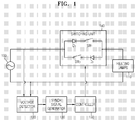
- FIG. 1 is a block diagram of an apparatus for controlling the power supplied to a fixing unit according to an exemplary embodiment of the present invention.
- the apparatus includes a power supply 100, heating lamps 110, a voltage detector 120, a synch signal generator 130, a switching unit 140, and a controller 150.
- the power supply 100 supplies alternating current (AC) power as input power for heating the heating lamps 110.
- AC alternating current
- the heating lamps 110 are used to heat a heating roller (not shown) of the fixing unit. Typically, halogen lamps are used as the heating lamps 110 but other types of lamps may also be used.
- the number of heating lamps 110 is at least one.
- the heating lamps 110 may be connected to one another serially or in parallel. In an alternative exemplary embodiment, the heating lamps 110 may be replaced with a different load.
- the voltage detector 120 detects an input voltage of the input power supplied by the power supply 100 and outputs a detection result to the synch signal generator 130.
- the synch signal generator 130 generates a synch signal corresponding to the input voltage detected by the input voltage detector 120 and outputs the generated power synch signal to the controller 150.
- the synch signal generator 130 generates a pulse signal synchronizing with a zero-crossing time of the input power as the synch signal.
- the switching unit 140 performs a switching operation to supply the input power provided by the power supply 100 to the heating lamps 110.
- the switching unit 140 performs the switching operation corresponding to a control signal of the controller 150.
- the switching unit 140 comprises at least one self turn-off switching component.
- the switching unit 140 comprises at least one diode connected in series to the at least one self turn-off switching component.
- a self turn-off switching component can perform an on switching operation or an off switching operation in response to a control signal.
- the switching unit 140 comprises a first self turn-off switching component SW 1 and a second self turn-off switching component SW 2 .
- the first self turn-off switching component SW 1 and the second self turn-off switching component SW 2 are connected in parallel.
- the self turn-off switching components may comprise a bipolar or field effect transistor or other self turn-off switches.
- the switching unit 140 also comprises a first diode D 1 and a second diode D 2 .
- the first diode D 1 is connected in series to the first self turn-off switching component SW 1
- the second diode D 2 is connected in series to the second self turn-off switching component SW 2 .
- the first diode D 1 and the first self turn-off switching component SW 1 are switching components for supplying the input power, a phase angle of which is within a range between 0° and 180°.
- the second diode D 2 and the second self turn-off switching component SW 2 are switching components for supplying the input power, a phase angle of which is within a range between 180° and 360°.
- the controller 150 has table information of temporal duty level values for the input power that is initially supplied.
- the controller 150 outputs a control signal for controlling the switching operation of the switching unit 140 to the switching unit 140 using the generated synch signal generated by the synch signal generator 130 and the table information.
- the table information duty level values are continuously increased for an initial time for which the input power is supplied.
- the initial time has elapsed during which the duty level values are being continuously increased, the table information reaches the maximum duty level value.
- the initial time can vary, in an exemplary embodiment, the initial time is set to a value between 1 second and 2 seconds in order to minimize an initial heating time of the heating lamps 110.
- Table 1 illustrates the table information.
- Time interval [sec]
- Duty level value [%]
- Switching component 0 ⁇ 1/120 5 SW 1 1/120 ⁇ 2/120 7 SW 2 2/120 ⁇ 3/120 10 SW 1 ... ... ... 118/120 ⁇ 119/120 95 SW 1 119/120 ⁇ 120/120 100 SW 2
- the controller 150 controls a switching operation of the first self turn-off switching component SW 1 so that a duty level value of the input power is 5% from 0 to 1/120 second.
- the controller 150 controls a switching operation of the second self turn-off switching component SW 2 so that a duty level value of the input power is 7% from 1/120 to 2/120 second.
- the controller 150 alternately controls the first self turn-off switching component SW 1 and the second self turn-off switching component SW 2 according to duty level values until 1 second elapses after the input power is supplied.
- FIG. 2 is a waveform diagram illustrating a variation of duty level values of an input power according to an exemplary embodiment of the present invention.
- a phase angle range between 0° and 180° of the input power corresponds to a time range between 0 and 1/120 second
- a phase angle range between 180° and 360° of the input power corresponds to a time range between 1/120 and 2/120 second.
- a sum of shaded areas during the time between 0 and 1/120 second corresponds to the duty level value of 5% of the input power to be supplied to the heating lamps 110 for the time between 0 and 1/120 second.
- a sum of shaded areas during the time between 1/120 and 2/120 second corresponds to the duty level value of 7% of the input power to be supplied to the heating lamps 110 for the time between 1/120 and 2/120 second.
- a sum of shaded areas during the time between 2/120 and 3/120 second corresponds to a duty level value of 10% of the input power to be supplied to the heating lamps 110 for the time between 2/120 and 3/120 second.
- a sum of shaded areas during a certain time corresponds to a duty level value of the certain time.
- the controller 150 can detect a zero crossing time of the input power using the generated synch signal.
- the controller 150 controls a switching operation of the first self turn-off switching component SW 1 or the second self turn-off switching component SW 2 every half period, in other words, 0° to 180° or 180° to 360°, of the input power based on the detected zero crossing time. That is, the controller 150 controls the switching operation of the first self turn-off switching component SW 1 so that the input power corresponding to the duty level value of 5% is supplied to the heating lamps 110 from 0 to 1/120 second. Thereafter, the controller 150 controls the switching operation of the second self turn-off switching component SW 2 so that the input power corresponding to the duty level value of 7% is supplied to the heating lamps 110 from 1/120 to 2/120 second.
- the controller 150 controls the switching operation of the first self-healing switching component SW 1 so that the input power corresponding to the duty level value of 10% is supplied to the heating lamps 110 from 2/120 to 3/120 second. Until the duty level value reaches the maximum value, in other words, 100%, the controller 150 alternately controls the switching operations of the first self turn-off switching component SW 1 and the second self turn-off switching component SW 2 .
- FIG. 3 is a waveform diagram illustrating the amplitude of the input power supplied to the heating lamps 110 for the initial time by the controller 150 of FIG. 1 , according to an exemplary embodiment of the present invention.
- the input power, which is initially supplied can be gradually increased and supplied.
- flickering and harmonic characteristics of a display device which occur due to an excessive supply of the input power, can be prevented, and by maximizing a duty level value for a time period, the initial heating time of the heating lamps 110 can be minimized.
- FIG. 4 is a flowchart illustrating a method of controlling the power supplied to a fixing unit according to an exemplary embodiment of the present invention.
- a voltage of an input power supplied to heat the heating lamps 110 is detected in operation 200.
- a synch signal of the detected voltage is generated.
- a pulse signal synchronizing with a zero-crossing time of the input power is generated as the synch signal.
- a control signal is output to control a switching operation of the switching unit 140, which switches a supply path of the input power supplied to the heating lamps 110, using the generated synch signal and table information of temporal duty level values of the input power, which is initially supplied.
- table information duty level values are continuously increased for an initial time for which the input power is supplied.
- the table information reaches the maximum duty level value.
- the initial time can vary, in an exemplary embodiment, the initial time is set to a value between 1 second and 2 seconds in order to minimize an initial heating time of the heating lamps 110.
- a zero crossing time of the input power can be detected using the generated synch signal.
- the switching operation of the first self turn-off switching component SW 1 or the second self turn-off switching component SW 2 illustrated in FIG. 1 is controlled every half period, in other words, 0° to 180° or 180° to 360°, of the input power based on the detected zero crossing time.
- the input power that is initially supplied is gradually increased, and thus, flickering and harmonic characteristics of a display device, which occur due to an excessive supply of the input power, can be prevented, and by maximizing a duty level value for a time period, the initial heating time of the heating lamps 110 can be minimized.
- the switching unit 140 performs the switching operation.
- the switching unit 140 comprises at least one self turn-off switching component.
- the switching unit 140 can perform an on switching operation or an off switching operation in response to a control signal.
- the exemplary embodiments of the present invention can be written as codes/instructions/programs and can be implemented in general-use digital computers that execute the codes/instructions/programs using a computer readable recording medium.
- the computer readable recording medium include magnetic storage media (e.g., ROM, floppy disks, hard disks, etc.), optical recording media (e.g., CD-ROMs, or DVDs), and storage media such as carrier waves (e.g., transmission through the Internet).
- the computer readable recording medium can also be distributed over network coupled computer systems so that the computer readable code is stored and executed in a distributed fashion. Also, functional programs, codes, and code segments for accomplishing the present invention can be easily construed by programmers skilled in the art to which the present invention pertains.
- the input power for initial heating of the heating lamps can be sequentially increased, thereby reducing flickering and harmonic characteristics of a display device.
Landscapes
- Physics & Mathematics (AREA)
- General Physics & Mathematics (AREA)
- Engineering & Computer Science (AREA)
- Microelectronics & Electronic Packaging (AREA)
- Fixing For Electrophotography (AREA)
- Control Of Resistance Heating (AREA)
- Control Of Temperature (AREA)
Claims (8)
- Appareil de commande de courant fourni à une unité de fixage d'un dispositif de formation d'images, l'appareil comprenant :au moins une lampe chauffante ;un détecteur de tension (120) pour détecter une tension de courant d'entrée fourni pour chauffer l'au moins une lampe chauffante (110) ;un générateur de signal de synchronisation (130) pour générer un signal de synchronisation en réponse à la tension détectée ;une unité de commutation (140) pour commuter un trajet d'alimentation du courant d'entrée à appliquer à l'au moins une lampe chauffante (110) ; etun dispositif de commande (150) présentant des informations de tableau de valeurs de niveau de cycle de service temporelles pour le courant d'entrée qui est initialement fourni, l'unité de commutation (140) pouvant fonctionner afin d'effectuer l'opération de commutation correspondant à un signal de commande, l'unité de commutation (140) comprenant au moins deux composants de commutation à arrêt automatique comportant un premier composant de commutation à arrêt automatique (SW1) et un second composant de commutation à arrêt automatique (SW2), caractérisé en ce que le dispositif de commande est configuré pour émettre le signal de commande afin de commander alternativement une opération de commutation du premier composant de commutation à arrêt automatique ou du second composant de commutation à arrêt automatique à chaque période de demi-onde de le courant d'entrée et afin de commander les premier et second composants de commutation respectifs de s'allumer et s'éteindre une pluralité de fois lors d'une période de demi-onde selon une valeur de niveau de cycle de service associée à la période de demi-onde à l'aide du signal de synchronisation généré et des informations de tableau.
- Appareil selon la revendication 1, dans lequel l'au moins une lampe chauffante (110) comprend une pluralité de lampes chauffantes (110) et la pluralité de lampes chauffantes (110) sont connectées en série ou en parallèle.
- Appareil selon l'une quelconque des revendications précédentes, dans lequel le premier composant de commutation à arrêt automatique (SW1) et le second composant de commutation à arrêt automatique (SW2) sont connectés en parallèle.
- Appareil selon la revendication 3, dans lequel l'unité de commutation (140) comprend en outre une première diode (D1) et une seconde diode (D2), la première diode (D1) étant connectée en série au premier composant de commutation à arrêt automatique (SW1), et la seconde diode (D2) étant connectée en série au second composant de commutation à arrêt automatique (SW2).
- Appareil selon l'une quelconque des revendications précédentes, dans lequel dans les informations de tableau, les valeurs de niveau de cycle de service sont augmentées en continu pendant un temps initial pendant lequel le courant d'entrée est fourni.
- Procédé de commande de courant fourni à une unité de fixage d'un dispositif de formation d'images, le procédé comprenant :la détection d'une tension de courant d'entrée fourni pour chauffer au moins une lampe chauffante (110) ;la génération d'un signal de synchronisation en réponse à la tension détectée ;l'émission d'un signal de commande pour commander une opération de commutation d'une unité de commutation (140) ; etla réalisation de l'opération de commutation par l'unité de commutation (140), l'unité de commutation (140) comprenant au moins deux composants de commutation à arrêt automatique comportant un premier composant de commutation à arrêt automatique (SW1) et un second composant de commutation à arrêt automatique (SW2),caractérisé en ce que le signal de commande commande alternativement une opération de commutation du premier composant de commutation à arrêt automatique ou du second composant de commutation à arrêt automatique à chaque période de demi-onde de le courant d'entrée et commande les premier et second composants de commutation de s'allumer et s'éteindre une pluralité de fois lors d'une période de demi-onde en fonction d'une valeur de niveau de cycle de service associée à la période de demi-onde à l'aide du signal de synchronisation généré et d'informations de tableau de valeurs de niveau de cycle de service temporelles pour le courant d'entrée qui est initialement fourni.
- Procédé selon la revendication 6, dans lequel dans les informations de tableau, les valeurs de niveau de cycle de service sont augmentées en continu pendant une période de temps initiale pendant laquelle le courant d'entrée est fourni.
- Support d'enregistrement lisible par ordinateur sur lequel ont été stockées des instructions pour amener l'appareil selon la revendication 1 à exécuter un procédé de commande d'un courant fourni à une unité de fixage d'un dispositif de formation d'images, les instructions comprenant :un premier ensemble d'instructions pour détecter une tension de courant d'entrée fourni pour chauffer l'au moins une lampe de chauffage (110) ;un deuxième ensemble d'instructions pour générer un signal de synchronisation en réponse à la tension détectée ;un troisième ensemble d'instructions pour émettre un signal de commande pour commander une opération de commutation de l'unité de commutation (140) ; etun quatrième ensemble d'instructions pour réaliser l'opération de commutation par l'unité de commutation (140),caractérisé en ce que le signal de commande commande alternativement une opération de commutation du premier composant de commutation à arrêt automatique ou du second composant de commutation à arrêt automatique toutes les demi-périodes d'onde du courant d'entrée et commande les premier et second composants de commutation respectifs de s'allumer et s'éteindre une pluralité de fois lors d'une période de demi-onde en fonction d'une valeur de niveau de cycle de service associée à la période de demi-onde à l'aide du signal de synchronisation généré et d'informations de tableau de valeurs de niveau de cycle de service temporelles pour le courant d'entrée qui est initialement fourni.
Applications Claiming Priority (1)
| Application Number | Priority Date | Filing Date | Title |
|---|---|---|---|
| KR1020060030150A KR100788690B1 (ko) | 2006-04-03 | 2006-04-03 | 정착기의 전원 공급 제어장치 및 방법 |
Publications (3)
| Publication Number | Publication Date |
|---|---|
| EP1843218A2 EP1843218A2 (fr) | 2007-10-10 |
| EP1843218A3 EP1843218A3 (fr) | 2014-05-28 |
| EP1843218B1 true EP1843218B1 (fr) | 2020-08-26 |
Family
ID=38197703
Family Applications (1)
| Application Number | Title | Priority Date | Filing Date |
|---|---|---|---|
| EP07101161.3A Not-in-force EP1843218B1 (fr) | 2006-04-03 | 2007-01-25 | Appareil et procédé de contrôle de puissance fournie à une unité de fixage |
Country Status (4)
| Country | Link |
|---|---|
| US (2) | US7721121B2 (fr) |
| EP (1) | EP1843218B1 (fr) |
| KR (1) | KR100788690B1 (fr) |
| CN (2) | CN101051205B (fr) |
Families Citing this family (8)
| Publication number | Priority date | Publication date | Assignee | Title |
|---|---|---|---|---|
| JP2009204716A (ja) * | 2008-02-26 | 2009-09-10 | Kyocera Mita Corp | 定着装置,画像形成装置 |
| JP5569063B2 (ja) * | 2009-03-18 | 2014-08-13 | 株式会社リコー | ヒータ制御装置、画像形成装置、ヒータ制御方法、プログラム |
| JP5794208B2 (ja) * | 2012-07-02 | 2015-10-14 | コニカミノルタ株式会社 | 画像形成装置 |
| CN104684113A (zh) * | 2013-11-26 | 2015-06-03 | 李飞宇 | 一种能够抑制谐波和闪烁的加热方法及装置 |
| JP6515275B2 (ja) * | 2014-11-19 | 2019-05-22 | コニカミノルタ株式会社 | 定着装置及び画像形成装置 |
| TWI578007B (zh) * | 2015-07-03 | 2017-04-11 | 群光電能科技股份有限公司 | 交流湧入電流測試器及交流湧入電流測試方法 |
| US9835690B2 (en) | 2015-10-16 | 2017-12-05 | Chicony Power Technology Co., Ltd. | AC inrush current testing device |
| JP2019113607A (ja) * | 2017-12-21 | 2019-07-11 | コニカミノルタ株式会社 | 定着装置、画像形成装置、および定着装置の制御方法 |
Citations (2)
| Publication number | Priority date | Publication date | Assignee | Title |
|---|---|---|---|---|
| JP2004212510A (ja) * | 2002-12-27 | 2004-07-29 | Canon Inc | 画像形成装置 |
| US20040188417A1 (en) * | 2003-03-28 | 2004-09-30 | Canon Kabushiki Kaisha | Heater drive circuit |
Family Cites Families (23)
| Publication number | Priority date | Publication date | Assignee | Title |
|---|---|---|---|---|
| JPH02166490A (ja) * | 1988-11-25 | 1990-06-27 | Nippon Kentek Kaisha Ltd | 画像形成装置に用いる熱定着装置用制御回路 |
| US5079409A (en) * | 1989-09-27 | 1992-01-07 | Mita Industrial Co., Ltd. | Heater control system |
| JPH0561379A (ja) * | 1991-08-30 | 1993-03-12 | Hitachi Ltd | 電子写真印刷装置 |
| US5669038A (en) * | 1995-04-27 | 1997-09-16 | Konica Corporation | Heater controlling apparatus and a fixing apparatus of an electrophotographic apparatus in use therewith |
| JP3185912B2 (ja) * | 1996-03-01 | 2001-07-11 | 京セラミタ株式会社 | 熱定着装置 |
| JP3847951B2 (ja) * | 1997-04-30 | 2006-11-22 | キヤノン株式会社 | 加熱制御装置 |
| US6301454B1 (en) * | 1997-09-18 | 2001-10-09 | Copyer Co., Ltd. | Fixing heater controlling method and an image forming device |
| JP2000276000A (ja) * | 1999-03-29 | 2000-10-06 | Ricoh Co Ltd | 熱定着装置 |
| JP2000330418A (ja) * | 1999-05-21 | 2000-11-30 | Ricoh Co Ltd | 定着装置 |
| JP2001005537A (ja) | 1999-06-25 | 2001-01-12 | Sharp Corp | 加熱制御装置 |
| JP4196244B2 (ja) * | 2000-07-31 | 2008-12-17 | コニカミノルタホールディングス株式会社 | ヒータ制御装置および画像形成装置 |
| JP2002296954A (ja) | 2001-03-29 | 2002-10-09 | Canon Inc | 加熱装置及びこの加熱装置を備える画像形成装置 |
| JP2003345171A (ja) | 2002-05-28 | 2003-12-03 | Ricoh Co Ltd | 定着温度制御方法,定着装置および画像形成装置 |
| JP2004021250A (ja) | 2002-06-18 | 2004-01-22 | Yutaka Sasaki | 光ファイバグレーティングカプラ型全光トランジスタ |
| JP4317383B2 (ja) * | 2002-06-19 | 2009-08-19 | 株式会社リコー | 画像形成装置 |
| JP2004303469A (ja) * | 2003-03-28 | 2004-10-28 | Brother Ind Ltd | 加熱装置及び画像形成装置 |
| JP2004343821A (ja) * | 2003-05-13 | 2004-12-02 | Canon Inc | 電力制御装置、及びこれを備えた画像形成装置 |
| US7295289B2 (en) * | 2003-07-11 | 2007-11-13 | Baker Hughes Incorporated | Continuous paper feed system |
| JP2005091965A (ja) * | 2003-09-19 | 2005-04-07 | Ricoh Co Ltd | 画像形成装置 |
| JP2005107048A (ja) * | 2003-09-29 | 2005-04-21 | Kyocera Mita Corp | 定着装置及び画像形成装置 |
| US6943326B2 (en) * | 2003-10-20 | 2005-09-13 | Hewlett-Packard Development Company, L.P. | Circuit for controlling a fusing system |
| KR100555678B1 (ko) | 2004-06-03 | 2006-03-22 | 삼성전자주식회사 | 전원동기신호 생성 및 전원전압 검출을 위한 정착기제어장치 |
| EP1632822B1 (fr) * | 2004-09-06 | 2017-04-05 | Canon Kabushiki Kaisha | Appareil de formation des images et procedé de formation des images |
-
2006
- 2006-04-03 KR KR1020060030150A patent/KR100788690B1/ko not_active Expired - Fee Related
- 2006-10-27 US US11/588,309 patent/US7721121B2/en active Active
-
2007
- 2007-01-25 EP EP07101161.3A patent/EP1843218B1/fr not_active Not-in-force
- 2007-01-31 CN CN2007100061202A patent/CN101051205B/zh not_active Expired - Fee Related
- 2007-01-31 CN CN201010556099.5A patent/CN102073256B/zh not_active Expired - Fee Related
-
2010
- 2010-01-21 US US12/656,220 patent/US8516276B2/en not_active Expired - Fee Related
Patent Citations (2)
| Publication number | Priority date | Publication date | Assignee | Title |
|---|---|---|---|---|
| JP2004212510A (ja) * | 2002-12-27 | 2004-07-29 | Canon Inc | 画像形成装置 |
| US20040188417A1 (en) * | 2003-03-28 | 2004-09-30 | Canon Kabushiki Kaisha | Heater drive circuit |
Also Published As
| Publication number | Publication date |
|---|---|
| KR20070099142A (ko) | 2007-10-09 |
| US8516276B2 (en) | 2013-08-20 |
| CN101051205B (zh) | 2011-01-19 |
| EP1843218A2 (fr) | 2007-10-10 |
| US20100125375A1 (en) | 2010-05-20 |
| KR100788690B1 (ko) | 2007-12-26 |
| US20070228842A1 (en) | 2007-10-04 |
| CN102073256A (zh) | 2011-05-25 |
| CN101051205A (zh) | 2007-10-10 |
| US7721121B2 (en) | 2010-05-18 |
| CN102073256B (zh) | 2014-01-29 |
| EP1843218A3 (fr) | 2014-05-28 |
Similar Documents
| Publication | Publication Date | Title |
|---|---|---|
| EP1843218B1 (fr) | Appareil et procédé de contrôle de puissance fournie à une unité de fixage | |
| US7813663B2 (en) | System and method of controlling temperature of fixing unit based on detected current | |
| JP6348825B2 (ja) | ヒータ制御装置及び画像形成装置 | |
| US8213822B2 (en) | Power control for a printer fuser | |
| JP2004078146A (ja) | 画像形成装置およびヒータ制御方法 | |
| WO2005122652A1 (fr) | Dispositif d’éclairage de lampe à décharge et projecteur | |
| JP2016136172A (ja) | ヒータ制御装置及び画像形成装置 | |
| US7186956B2 (en) | Fuser-controlling apparatus for generating a power synchronization signal and detecting power voltage | |
| US7329840B2 (en) | Heater lamp control apparatus and method to detect an inputted AC voltage and providing a pulse signal to correspond thereto | |
| JP4666329B2 (ja) | 画像形成装置 | |
| JP5011648B2 (ja) | フリッカ抑制装置およびフリッカ抑制方法および画像形成装置の定着装置 | |
| KR101217629B1 (ko) | 위상 제어 회로 및 이를 이용한 히터램프 제어장치 및 방법 | |
| JPH09319441A (ja) | 電力制御装置 | |
| EP1835360A2 (fr) | Système et procédé de contrôle de fixation d'image | |
| JP6654412B2 (ja) | 電源装置および画像形成装置 | |
| JP3799161B2 (ja) | 誘導加熱調理器 | |
| JPH09274407A (ja) | 定着ヒータ制御装置 | |
| JPH06214662A (ja) | 温度制御装置 | |
| JP2004200179A (ja) | 電気ヒータ制御装置 | |
| JP2004020663A (ja) | プリント装置 | |
| JPH09297494A (ja) | 画像形成装置の定着ヒータ制御装置 | |
| JPH07234728A (ja) | コンポーネントのパラメータ制御方法 | |
| KR20070080452A (ko) | 정착 가열 롤러를 위한 전력 제어 방법 및 장치 | |
| JPH11305592A (ja) | 画像形成装置および加熱制御法 | |
| JP2007519201A (ja) | マルチスロープ電流フィードバックを有する電子バラスト |
Legal Events
| Date | Code | Title | Description |
|---|---|---|---|
| PUAI | Public reference made under article 153(3) epc to a published international application that has entered the european phase |
Free format text: ORIGINAL CODE: 0009012 |
|
| 17P | Request for examination filed |
Effective date: 20070125 |
|
| AK | Designated contracting states |
Kind code of ref document: A2 Designated state(s): AT BE BG CH CY CZ DE DK EE ES FI FR GB GR HU IE IS IT LI LT LU LV MC NL PL PT RO SE SI SK TR |
|
| AX | Request for extension of the european patent |
Extension state: AL BA HR MK RS |
|
| RAP1 | Party data changed (applicant data changed or rights of an application transferred) |
Owner name: SAMSUNG ELECTRONICS CO., LTD. |
|
| PUAL | Search report despatched |
Free format text: ORIGINAL CODE: 0009013 |
|
| AK | Designated contracting states |
Kind code of ref document: A3 Designated state(s): AT BE BG CH CY CZ DE DK EE ES FI FR GB GR HU IE IS IT LI LT LU LV MC NL PL PT RO SE SI SK TR |
|
| AX | Request for extension of the european patent |
Extension state: AL BA HR MK RS |
|
| RIC1 | Information provided on ipc code assigned before grant |
Ipc: G03G 15/20 20060101ALI20140424BHEP Ipc: G03G 15/00 20060101AFI20140424BHEP |
|
| AKX | Designation fees paid |
Designated state(s): DE FR GB NL |
|
| AXX | Extension fees paid |
Extension state: AL Extension state: BA Extension state: HR Extension state: MK Extension state: RS |
|
| RAP1 | Party data changed (applicant data changed or rights of an application transferred) |
Owner name: S-PRINTING SOLUTION CO., LTD. |
|
| RAP1 | Party data changed (applicant data changed or rights of an application transferred) |
Owner name: HP PRINTING KOREA CO., LTD. |
|
| STAA | Information on the status of an ep patent application or granted ep patent |
Free format text: STATUS: EXAMINATION IS IN PROGRESS |
|
| 17Q | First examination report despatched |
Effective date: 20180808 |
|
| RAP1 | Party data changed (applicant data changed or rights of an application transferred) |
Owner name: HEWLETT-PACKARD DEVELOPMENT COMPANY, L.P. |
|
| GRAP | Despatch of communication of intention to grant a patent |
Free format text: ORIGINAL CODE: EPIDOSNIGR1 |
|
| STAA | Information on the status of an ep patent application or granted ep patent |
Free format text: STATUS: GRANT OF PATENT IS INTENDED |
|
| INTG | Intention to grant announced |
Effective date: 20200325 |
|
| GRAS | Grant fee paid |
Free format text: ORIGINAL CODE: EPIDOSNIGR3 |
|
| GRAA | (expected) grant |
Free format text: ORIGINAL CODE: 0009210 |
|
| STAA | Information on the status of an ep patent application or granted ep patent |
Free format text: STATUS: THE PATENT HAS BEEN GRANTED |
|
| AK | Designated contracting states |
Kind code of ref document: B1 Designated state(s): DE FR GB NL |
|
| REG | Reference to a national code |
Ref country code: GB Ref legal event code: FG4D |
|
| REG | Reference to a national code |
Ref country code: DE Ref legal event code: R096 Ref document number: 602007060580 Country of ref document: DE |
|
| REG | Reference to a national code |
Ref country code: NL Ref legal event code: MP Effective date: 20200826 |
|
| PG25 | Lapsed in a contracting state [announced via postgrant information from national office to epo] |
Ref country code: NL Free format text: LAPSE BECAUSE OF FAILURE TO SUBMIT A TRANSLATION OF THE DESCRIPTION OR TO PAY THE FEE WITHIN THE PRESCRIBED TIME-LIMIT Effective date: 20200826 |
|
| REG | Reference to a national code |
Ref country code: DE Ref legal event code: R097 Ref document number: 602007060580 Country of ref document: DE |
|
| PLBE | No opposition filed within time limit |
Free format text: ORIGINAL CODE: 0009261 |
|
| STAA | Information on the status of an ep patent application or granted ep patent |
Free format text: STATUS: NO OPPOSITION FILED WITHIN TIME LIMIT |
|
| PGFP | Annual fee paid to national office [announced via postgrant information from national office to epo] |
Ref country code: FR Payment date: 20210608 Year of fee payment: 16 |
|
| 26N | No opposition filed |
Effective date: 20210527 |
|
| PGFP | Annual fee paid to national office [announced via postgrant information from national office to epo] |
Ref country code: GB Payment date: 20211216 Year of fee payment: 16 |
|
| PGFP | Annual fee paid to national office [announced via postgrant information from national office to epo] |
Ref country code: DE Payment date: 20210528 Year of fee payment: 16 |
|
| REG | Reference to a national code |
Ref country code: DE Ref legal event code: R119 Ref document number: 602007060580 Country of ref document: DE |
|
| GBPC | Gb: european patent ceased through non-payment of renewal fee |
Effective date: 20230125 |
|
| PG25 | Lapsed in a contracting state [announced via postgrant information from national office to epo] |
Ref country code: GB Free format text: LAPSE BECAUSE OF NON-PAYMENT OF DUE FEES Effective date: 20230125 Ref country code: DE Free format text: LAPSE BECAUSE OF NON-PAYMENT OF DUE FEES Effective date: 20230801 |
|
| PG25 | Lapsed in a contracting state [announced via postgrant information from national office to epo] |
Ref country code: FR Free format text: LAPSE BECAUSE OF NON-PAYMENT OF DUE FEES Effective date: 20230131 |