EP1843578A2 - Multimediagerät zum Empfangen audiovisueller Sendungen - Google Patents
Multimediagerät zum Empfangen audiovisueller Sendungen Download PDFInfo
- Publication number
- EP1843578A2 EP1843578A2 EP20070113147 EP07113147A EP1843578A2 EP 1843578 A2 EP1843578 A2 EP 1843578A2 EP 20070113147 EP20070113147 EP 20070113147 EP 07113147 A EP07113147 A EP 07113147A EP 1843578 A2 EP1843578 A2 EP 1843578A2
- Authority
- EP
- European Patent Office
- Prior art keywords
- mode
- switching
- supply voltage
- communication
- connector
- Prior art date
- Legal status (The legal status is an assumption and is not a legal conclusion. Google has not performed a legal analysis and makes no representation as to the accuracy of the status listed.)
- Ceased
Links
Images

Classifications
-
- H—ELECTRICITY
- H04—ELECTRIC COMMUNICATION TECHNIQUE
- H04N—PICTORIAL COMMUNICATION, e.g. TELEVISION
- H04N21/00—Selective content distribution, e.g. interactive television or video on demand [VOD]
- H04N21/40—Client devices specifically adapted for the reception of or interaction with content, e.g. set-top-box [STB]; Operations thereof
- H04N21/43—Processing of content or additional data, e.g. demultiplexing additional data from a digital video stream; Elementary client operations, e.g. monitoring of home network or synchronising decoder's clock; Client middleware
- H04N21/443—OS processes, e.g. booting an STB, implementing a Java virtual machine in an STB or power management in an STB
- H04N21/4432—Powering on the client, e.g. bootstrap loading using setup parameters being stored locally or received from the server
-
- G—PHYSICS
- G06—COMPUTING OR CALCULATING; COUNTING
- G06F—ELECTRIC DIGITAL DATA PROCESSING
- G06F13/00—Interconnection of, or transfer of information or other signals between, memories, input/output devices or central processing units
-
- H—ELECTRICITY
- H04—ELECTRIC COMMUNICATION TECHNIQUE
- H04N—PICTORIAL COMMUNICATION, e.g. TELEVISION
- H04N21/00—Selective content distribution, e.g. interactive television or video on demand [VOD]
- H04N21/40—Client devices specifically adapted for the reception of or interaction with content, e.g. set-top-box [STB]; Operations thereof
- H04N21/41—Structure of client; Structure of client peripherals
- H04N21/4104—Peripherals receiving signals from specially adapted client devices
- H04N21/4113—PC
-
- H—ELECTRICITY
- H04—ELECTRIC COMMUNICATION TECHNIQUE
- H04N—PICTORIAL COMMUNICATION, e.g. TELEVISION
- H04N21/00—Selective content distribution, e.g. interactive television or video on demand [VOD]
- H04N21/40—Client devices specifically adapted for the reception of or interaction with content, e.g. set-top-box [STB]; Operations thereof
- H04N21/41—Structure of client; Structure of client peripherals
- H04N21/426—Internal components of the client ; Characteristics thereof
-
- H—ELECTRICITY
- H04—ELECTRIC COMMUNICATION TECHNIQUE
- H04N—PICTORIAL COMMUNICATION, e.g. TELEVISION
- H04N21/00—Selective content distribution, e.g. interactive television or video on demand [VOD]
- H04N21/40—Client devices specifically adapted for the reception of or interaction with content, e.g. set-top-box [STB]; Operations thereof
- H04N21/43—Processing of content or additional data, e.g. demultiplexing additional data from a digital video stream; Elementary client operations, e.g. monitoring of home network or synchronising decoder's clock; Client middleware
- H04N21/436—Interfacing a local distribution network, e.g. communicating with another STB or one or more peripheral devices inside the home
- H04N21/4363—Adapting the video stream to a specific local network, e.g. a Bluetooth® network
- H04N21/43632—Adapting the video stream to a specific local network, e.g. a Bluetooth® network involving a wired protocol, e.g. IEEE 1394
-
- H—ELECTRICITY
- H04—ELECTRIC COMMUNICATION TECHNIQUE
- H04N—PICTORIAL COMMUNICATION, e.g. TELEVISION
- H04N21/00—Selective content distribution, e.g. interactive television or video on demand [VOD]
- H04N21/40—Client devices specifically adapted for the reception of or interaction with content, e.g. set-top-box [STB]; Operations thereof
- H04N21/43—Processing of content or additional data, e.g. demultiplexing additional data from a digital video stream; Elementary client operations, e.g. monitoring of home network or synchronising decoder's clock; Client middleware
- H04N21/442—Monitoring of processes or resources, e.g. detecting the failure of a recording device, monitoring the downstream bandwidth, the number of times a movie has been viewed, the storage space available from the internal hard disk
- H04N21/4424—Monitoring of the internal components or processes of the client device, e.g. CPU or memory load, processing speed, timer, counter or percentage of the hard disk space used
-
- H—ELECTRICITY
- H04—ELECTRIC COMMUNICATION TECHNIQUE
- H04N—PICTORIAL COMMUNICATION, e.g. TELEVISION
- H04N21/00—Selective content distribution, e.g. interactive television or video on demand [VOD]
- H04N21/40—Client devices specifically adapted for the reception of or interaction with content, e.g. set-top-box [STB]; Operations thereof
- H04N21/45—Management operations performed by the client for facilitating the reception of or the interaction with the content or administrating data related to the end-user or to the client device itself, e.g. learning user preferences for recommending movies, resolving scheduling conflicts
- H04N21/462—Content or additional data management e.g. creating a master electronic programme guide from data received from the Internet and a Head-end or controlling the complexity of a video stream by scaling the resolution or bit-rate based on the client capabilities
- H04N21/4622—Retrieving content or additional data from different sources, e.g. from a broadcast channel and the Internet
-
- H—ELECTRICITY
- H04—ELECTRIC COMMUNICATION TECHNIQUE
- H04N—PICTORIAL COMMUNICATION, e.g. TELEVISION
- H04N5/00—Details of television systems
- H04N5/63—Generation or supply of power specially adapted for television receivers
Definitions
- the present invention relates to a multimedia audiovisual transmission reception device that can, for example, be connected to a personal computer.
- the multimedia audiovisual transmission reception apparatus may, for example, be constituted by a decoder or any other apparatus capable of being connected to a bidirectional wired network.
- This return channel will be used for interactivity functions between the user of the decoded audio program and the operator of the television network.
- the current digital decoders to comply with the European standard in force, have a standby mode with low consumption. This state is reached when only the functions necessary to wake up the multimedia device are powered. For example, the decoder then in standby mode must be able to be woken to record a VCR television program.
- This alarm function is activated either by the remote control of the decoder, or by the keyboard of the front face of the decoder. A signal emitted by the remote control and received by the photoreceptor on the front of the decoder or an activation of the keys of the keyboard will cause an interruption on the keyboard processor of the decoder which is the only processor to remain permanently active and to monitor the interruptions which can be caused by one of these two events.
- Such a decoder can therefore be used as a communication interface between a PC and an operator if it is not provided with a device for waking it up.
- a first object of the invention is to provide a multimedia audiovisual transmission reception apparatus, such as for example a digital decoder, equipment necessary to allow the passage from a reduced mode of operation, for example standby, to a mode of normal operation, allowing in particular the connection of a source device, such as for example a computer, to the Internet.
- a multimedia audiovisual transmission reception apparatus such as for example a digital decoder, equipment necessary to allow the passage from a reduced mode of operation, for example standby, to a mode of normal operation, allowing in particular the connection of a source device, such as for example a computer, to the Internet.
- a method for switching an apparatus (20) from a first mode of operation, said standby mode, to a second mode of operation, called an alarm clock comprising: a communication circuit (9, 8, 10, 3, 7) with means for connection to a bidirectional communication network, a connector (11) for communication with a source apparatus (17), said connector comprising at least one conductor (VBUS) for transmitting a supply voltage from the source apparatus (17), characterized in that it comprises a step of detection by a detection means (1) of the presence of said supply voltage (VBUS) connected to the connector (11), said detection means (1) generating, a signal of detection at the appearance of the supply voltage, to the communication circuit (3), said detection step triggering at the appearance of the bus supply voltage a switching step of the device (20) of the first mode of operation, said standby for which the communication circuit (3) has the minimum of active functions in the second operating mode, said alarm for which the communication circuit (3) has its communication function, between the connector (11); ) and the network, enabled.
- the switching circuit is constituted by a first microprocessor of a control means of the multimedia apparatus and a program for triggering the awakening actions constituting the wake-up sequence of the communication circuit.
- control means is a control keyboard and / or a remote control receiver of said multimedia apparatus, said control means being connected to an interrupt input of said first microprocessor.
- the detection means are connected to an interruption input of the first microprocessor receiving the detection signal.
- the first microprocessor is connected to a general power supply circuit of the multimedia apparatus for activating said supply circuit in response to the appearance of the detection signal.
- the detection means consist of an electronic switch generating a voltage on one of the inputs of the first microprocessor.
- said apparatus comprises a digital television decoder, said communication circuit comprising a connection circuit to a bidirectional wired network.
- said apparatus comprises an interface circuit adapted to the type of connector connected to the internal bus of the digital decoder connecting a main processor of the decoder to a return channel processor of the digital decoder, said return channel processor being connected by an interface circuit to a bidirectional wired network cable connecting the digital decoder to the service of the audiovisual operator server.
- said apparatus comprises means for triggering the connection to the Internet through the service of the audiovisual operator's server.
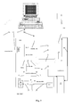
- FIGS. 1 and 2 A non-limiting embodiment of the invention will now be described with FIGS. 1 and 2.
- This connection is allowed with a minor modification of the multimedia device, in the given example, of the decoder.
- This minor modification consists in integrating in the decoder a USB connector (11) whose input terminal (VBUS) is connected to a circuit (1) for detecting the voltage VBUS (that is to say the supply voltage of the USB bus generated by the master).
- This circuit (1) belongs to a USB interface circuit (9), which is connected to the input terminals (DATA +, DATA-) and the ground of the USB connector (11).
- the output of the detection circuit (1) is connected by a link (2) to an interrupt input of a microprocessor (3) which is the microprocessor of the decoder keyboard and the front panel.
- This microprocessor is connected by a link (4) to the main power supply circuit (5) and an I2C bus (12) to the main processor (7).
- the main power supply supplies the main microprocessor (7).
- the invention is also used to detect an interruption related to the detection of the connection of a USB connector.
- the microprocessor can continuously monitor its digital inputs (polling) to detect changes in states of the inputs and perform the desired treatments.
- the decoder In its operation, the decoder, when it detects by its microprocessor (3) an interruption, sends a signal through the link (4) to the main power supply of the entire decoder which then feeds through the (link (6) ) the main processor (7) to wake the decoder functions necessary for the controlled function.
- This feature will allow the recording of a TV program on the VCR or the viewing of a channel received by the decoder on the television or the use of the decoder as a modem.
- the main processor (7) communicates with an audio, video, digital signal transport bus (15) and the associated RF receiver decoder stage (13). by a branch cable (14 ') to the input-output cable (14) of the decoder.
- the keyboard or front panel microprocessor (3) is associated by its processor bus (31) with a memory, which contains a program module (30) which manages the interrupts appearing on the lines (18) to trigger, as a function of these interruptions, the awakening of the entire decoder.
- the exemplary embodiment of the invention consists in adding in addition to the detection circuit (1) a line (2) at the output of the circuit (1) for detecting the voltage VBUS, this line being sent to an interrupt input high level of the microprocessor (3) to trigger the execution of a program module (32) processing the interruption and realizing, firstly, the sending by the line (4) of a wake-up signal of the main power supply (5) of the decoder and then by the I2C bus (12), sending a command to the main processor (7), so that it communicates with the microprocessor (10) of the back through the processor bus (8) and to put it on hold for the arrival of signals on its bus (8) from the interface card (9) of the USB connector (11).
- the interface circuit (9) will have the role of transforming the USB signal exchange protocol between the personal computer (17) and the interface circuit (9) into a compatible communication protocol between the two processors. (10) return channel and (7) main via the bus (8).
- the VBUS terminal of the USB connector is connected to a common point (100), which is connected firstly through a resistor (101) to ground and secondly to the base of a PNP transistor (106).
- the PNP transistor has its collector connected to ground and its emitter connected to the common point (107) and a resistor (105), the second of which end is connected to the voltage supply point VCC.
- the last common point (107) outputs the detection signal of the presence of the voltage VBUS on the line (2) which is connected to the higher level interrupt input of the microprocessor (3) of the front panel.
- the other elements of FIG. 2 are identical to those of FIG. 1 and are designated by the same references.
- the interface part (9, 10) of the decoder operates in slave mode with respect to the personal computer (17), which means that control signals for interactive television functions from the remote control are either momentarily rendered inactive by the main processor (7) and a display controlled by this processor (7) indicates to the user that the interactivity function is interrupted following an Internet connection or the microprocessor (7) multiplexes these signals with those from the personal computer (17).
- the USB interface (9) incorporates in the signals from the USB bus an identifier and the main microprocessor (7) also incorporates in the signals from the remote control a different identifier allowing the service (21) of the operator to distinguish between signals from the personal computer (17) for the Internet link and those intended to produce changes to the delivered services from the remote control.
- the computer automatically wakes up the decoder by activating the voltage on the USB bus, which makes it possible to prepare a communication via the wired network.
Landscapes
- Engineering & Computer Science (AREA)
- Multimedia (AREA)
- Signal Processing (AREA)
- Databases & Information Systems (AREA)
- Computer Networks & Wireless Communication (AREA)
- General Engineering & Computer Science (AREA)
- Theoretical Computer Science (AREA)
- Software Systems (AREA)
- General Physics & Mathematics (AREA)
- Physics & Mathematics (AREA)
- Two-Way Televisions, Distribution Of Moving Picture Or The Like (AREA)
- Power Sources (AREA)
- Small-Scale Networks (AREA)
Applications Claiming Priority (2)
| Application Number | Priority Date | Filing Date | Title |
|---|---|---|---|
| FR0008238A FR2810833B1 (fr) | 2000-06-27 | 2000-06-27 | Appareil multimedia de reception d4emission audiovisuelle |
| EP01949545A EP1295473A1 (de) | 2000-06-27 | 2001-06-27 | Multimediengerät zum empfang einer audio-visuellen übertragung |
Related Parent Applications (1)
| Application Number | Title | Priority Date | Filing Date |
|---|---|---|---|
| EP01949545A Division EP1295473A1 (de) | 2000-06-27 | 2001-06-27 | Multimediengerät zum empfang einer audio-visuellen übertragung |
Publications (2)
| Publication Number | Publication Date |
|---|---|
| EP1843578A2 true EP1843578A2 (de) | 2007-10-10 |
| EP1843578A3 EP1843578A3 (de) | 2007-11-21 |
Family
ID=8851737
Family Applications (2)
| Application Number | Title | Priority Date | Filing Date |
|---|---|---|---|
| EP20070113147 Ceased EP1843578A3 (de) | 2000-06-27 | 2001-06-27 | Multimediagerät zum Empfangen audiovisueller Sendungen |
| EP01949545A Ceased EP1295473A1 (de) | 2000-06-27 | 2001-06-27 | Multimediengerät zum empfang einer audio-visuellen übertragung |
Family Applications After (1)
| Application Number | Title | Priority Date | Filing Date |
|---|---|---|---|
| EP01949545A Ceased EP1295473A1 (de) | 2000-06-27 | 2001-06-27 | Multimediengerät zum empfang einer audio-visuellen übertragung |
Country Status (9)
| Country | Link |
|---|---|
| US (1) | US7853807B2 (de) |
| EP (2) | EP1843578A3 (de) |
| JP (1) | JP4711596B2 (de) |
| KR (1) | KR100768146B1 (de) |
| CN (1) | CN1180616C (de) |
| AU (1) | AU2001270676A1 (de) |
| FR (1) | FR2810833B1 (de) |
| MX (1) | MXPA02012508A (de) |
| WO (1) | WO2002001865A1 (de) |
Families Citing this family (9)
| Publication number | Priority date | Publication date | Assignee | Title |
|---|---|---|---|---|
| US7221410B2 (en) * | 2002-12-16 | 2007-05-22 | Samsung Electro-Mechanics Co., Ltd. | Television receiving module and display apparatus and television receiving system using the same |
| JP2007503657A (ja) * | 2003-05-26 | 2007-02-22 | コーニンクレッカ フィリップス エレクトロニクス エヌ ヴィ | 家電装置用の信号接続及びエネルギー供給装置 |
| JP2007013438A (ja) * | 2005-06-29 | 2007-01-18 | Toshiba Corp | 音声画像再生装置及び動作制御方法 |
| KR101463471B1 (ko) * | 2007-06-05 | 2014-11-19 | 삼성전자주식회사 | 외부장치의 상태를 알리는 디스플레이장치 및 그 방법 |
| US8734648B2 (en) * | 2007-09-11 | 2014-05-27 | Siemens Energy, Inc. | Treatment of spent caustic waste |
| KR100960652B1 (ko) * | 2007-12-28 | 2010-06-07 | 모다정보통신 주식회사 | 휴대 인터넷과 디지털 방송의 동시 서비스를 지원하는usb방식의 무선 모뎀 장치 |
| US9077108B2 (en) * | 2010-08-20 | 2015-07-07 | Rockwell Automation Technologies, Inc. | Input/output module bus contact system and method |
| JP6163730B2 (ja) * | 2012-10-25 | 2017-07-19 | 株式会社リコー | 画像出力装置、画像出力装置の制御プログラム |
| CN105516717A (zh) * | 2015-12-11 | 2016-04-20 | 康佳集团股份有限公司 | 用于电视整机自动测试的电视信源无线切换方法及系统 |
Citations (5)
| Publication number | Priority date | Publication date | Assignee | Title |
|---|---|---|---|---|
| EP0508685A2 (de) * | 1991-04-10 | 1992-10-14 | International Business Machines Corporation | Anschaltsteuerungssystem für einen Computer |
| EP0724208A1 (de) * | 1995-01-24 | 1996-07-31 | Hewlett-Packard Company | Steuerung des Netzteillieferungssystems in einem Rechner |
| US5608545A (en) * | 1993-01-18 | 1997-03-04 | Ricoh Company, Ltd. | Facsimile device and communication control method thereof |
| EP0862313A2 (de) * | 1997-02-28 | 1998-09-02 | Canon Kabushiki Kaisha | Bildein-/ausgabesystem |
| EP0952530A2 (de) * | 1998-04-23 | 1999-10-27 | Sony Corporation | USB-Vorrichtung und USB- Knotenpunktvorrichtung |
Family Cites Families (19)
| Publication number | Priority date | Publication date | Assignee | Title |
|---|---|---|---|---|
| US5404544A (en) * | 1992-06-05 | 1995-04-04 | Advanced Micro Devices | System for periodically transmitting signal to/from sleeping node identifying its existence to a network and awakening the sleeping node responding to received instruction |
| US5666293A (en) * | 1994-05-27 | 1997-09-09 | Bell Atlantic Network Services, Inc. | Downloading operating system software through a broadcast channel |
| GB9526304D0 (en) * | 1995-05-22 | 1996-02-21 | British Sky Broadcasting Ltd | Interactive services interface |
| US5756280A (en) * | 1995-10-03 | 1998-05-26 | International Business Machines Corporation | Multimedia distribution network including video switch |
| DE19611945C1 (de) * | 1996-03-26 | 1997-11-20 | Daimler Benz Ag | Einrichtung für den busvernetzten Betrieb eines elektronischen Gerätes mit Microcontroller sowie deren Verwendung |
| DE19622366B4 (de) * | 1996-06-04 | 2006-01-26 | Deutsche Telekom Ag | ISDN-Anschlußsystem |
| US5799196A (en) * | 1996-07-02 | 1998-08-25 | Gateway 2000, Inc. | Method and apparatus of providing power management using a self-powered universal serial bus (USB) device |
| TW420931B (en) * | 1996-08-22 | 2001-02-01 | Hitachi Ltd | Television receiver and receiving method thereof |
| KR19980043574A (ko) | 1996-12-04 | 1998-09-05 | 문정환 | 멀티미디어 기록, 재생장치 및 그의 제어방법 |
| US6314479B1 (en) * | 1997-08-04 | 2001-11-06 | Compaq Computer Corporation | Universal multi-pin plug and display connector for standardizing signals transmitted between a computer and a display for a PC theatre interconnectivity system |
| US5974486A (en) * | 1997-08-12 | 1999-10-26 | Atmel Corporation | Universal serial bus device controller comprising a FIFO associated with a plurality of endpoints and a memory for storing an identifier of a current endpoint |
| US5954820A (en) * | 1997-09-26 | 1999-09-21 | International Business Machines Corporation | Portable computer with adaptive demand-driven power management |
| DE19758273B4 (de) * | 1997-12-31 | 2005-06-02 | Deutsche Telekom Ag | Notspeisefähige Stromversorgung für ISDN-Endsysteme |
| JPH11212681A (ja) | 1998-01-23 | 1999-08-06 | Canon Inc | 周辺装置および消費電力低減方法 |
| JPH11345207A (ja) * | 1998-06-03 | 1999-12-14 | Toshiba Corp | コンピュータシステムおよびその制御方法 |
| JPH11353266A (ja) * | 1998-06-10 | 1999-12-24 | Toshiba Corp | コンピュータシステムおよび同システムの状態制御方法 |
| EP0984631A1 (de) * | 1998-09-04 | 2000-03-08 | THOMSON multimedia | Vorrichtung und Verfahren zur Ausführung von interaktiven Fernsehanwendungen auf Set Top Boxen |
| KR100331833B1 (ko) * | 1999-11-08 | 2002-04-09 | 구자홍 | 티브이와 컴퓨터 간의 연결장치 |
| FR2813740B1 (fr) * | 2000-09-05 | 2003-01-03 | Thomson Multimedia Sa | Appareil de reception d'emissions audiovisuelles |
-
2000
- 2000-06-27 FR FR0008238A patent/FR2810833B1/fr not_active Expired - Fee Related
-
2001
- 2001-06-27 EP EP20070113147 patent/EP1843578A3/de not_active Ceased
- 2001-06-27 US US10/311,725 patent/US7853807B2/en not_active Expired - Fee Related
- 2001-06-27 AU AU2001270676A patent/AU2001270676A1/en not_active Abandoned
- 2001-06-27 WO PCT/FR2001/002038 patent/WO2002001865A1/fr not_active Ceased
- 2001-06-27 MX MXPA02012508A patent/MXPA02012508A/es active IP Right Grant
- 2001-06-27 EP EP01949545A patent/EP1295473A1/de not_active Ceased
- 2001-06-27 KR KR1020027017602A patent/KR100768146B1/ko not_active Expired - Lifetime
- 2001-06-27 JP JP2002505510A patent/JP4711596B2/ja not_active Expired - Lifetime
- 2001-06-27 CN CNB018119018A patent/CN1180616C/zh not_active Expired - Lifetime
Patent Citations (5)
| Publication number | Priority date | Publication date | Assignee | Title |
|---|---|---|---|---|
| EP0508685A2 (de) * | 1991-04-10 | 1992-10-14 | International Business Machines Corporation | Anschaltsteuerungssystem für einen Computer |
| US5608545A (en) * | 1993-01-18 | 1997-03-04 | Ricoh Company, Ltd. | Facsimile device and communication control method thereof |
| EP0724208A1 (de) * | 1995-01-24 | 1996-07-31 | Hewlett-Packard Company | Steuerung des Netzteillieferungssystems in einem Rechner |
| EP0862313A2 (de) * | 1997-02-28 | 1998-09-02 | Canon Kabushiki Kaisha | Bildein-/ausgabesystem |
| EP0952530A2 (de) * | 1998-04-23 | 1999-10-27 | Sony Corporation | USB-Vorrichtung und USB- Knotenpunktvorrichtung |
Also Published As
| Publication number | Publication date |
|---|---|
| CN1180616C (zh) | 2004-12-15 |
| US7853807B2 (en) | 2010-12-14 |
| AU2001270676A1 (en) | 2002-01-08 |
| EP1843578A3 (de) | 2007-11-21 |
| FR2810833B1 (fr) | 2002-09-20 |
| KR20030014728A (ko) | 2003-02-19 |
| KR100768146B1 (ko) | 2007-10-18 |
| MXPA02012508A (es) | 2003-04-25 |
| JP4711596B2 (ja) | 2011-06-29 |
| US20040025188A1 (en) | 2004-02-05 |
| JP2004502217A (ja) | 2004-01-22 |
| WO2002001865A1 (fr) | 2002-01-03 |
| FR2810833A1 (fr) | 2001-12-28 |
| EP1295473A1 (de) | 2003-03-26 |
| CN1439223A (zh) | 2003-08-27 |
Similar Documents
| Publication | Publication Date | Title |
|---|---|---|
| US7865922B2 (en) | Low-power broadcast receiver | |
| KR100205549B1 (ko) | 브이.오.디. 용 셋탑보드 및 셋탑보드가 장착된 컴퓨터 시스템 | |
| US6212327B1 (en) | Controlling record/playback devices with a computer | |
| US20050134746A1 (en) | Controllable video switching method and apparatus | |
| US8077341B2 (en) | Printer with audio or video receiver, recorder, and real-time content-based processing logic | |
| CA2571767A1 (en) | Lower-power standby mode for consumer electronics | |
| EP1843578A2 (de) | Multimediagerät zum Empfangen audiovisueller Sendungen | |
| CN107291416A (zh) | 一种音频播放方法、系统及终端设备 | |
| WO2012168391A1 (fr) | Procede de sortie d'un mode de veille basse consommation et dispositif associe | |
| FR2813740A1 (fr) | Appareil de reception d'emissions audiovisuelles | |
| FR2813741A1 (fr) | Appareil maitre/esclave de reception d'emissions audiovisuelles | |
| US20240205501A1 (en) | Management of standby of a multimedia stream reader terminal | |
| TW201734972A (zh) | 自動提醒異常監控狀況的多媒體播放系統及其資訊處理方法 | |
| WO2022217806A1 (zh) | 语音遥控器的控制方法、装置、设备、系统及存储介质 | |
| WO2010082148A1 (en) | Method and system for controlling the working status of an electric device | |
| EP2200292A1 (de) | Automatisches Steuerverfahren eines Gehäuses eines externern Fernsehers, und entsprechendes Gehäuse des externen Fernsehers | |
| KR100480716B1 (ko) | 디지털 티브이의 영상 메시지 전달 장치 및 방법 | |
| US20100188578A1 (en) | Real Time Information Display Module and Method Thereof | |
| CN115119059A (zh) | 开关机顶盒方法、装置、机顶盒和存储介质 | |
| KR20010001731A (ko) | 멀티미디어 디바이스 제어용 텔레비전 | |
| KR20110068432A (ko) | 디지털 방송 수신기의 전원 관리 장치 및 방법 | |
| FR2961933A1 (fr) | Dispositif local de surveillance d'une personne par l'observation de son utilisation d'un systeme audio/video | |
| FR2717278A1 (fr) | Alimentation pour l'unité centrale et les périphériques de micro-ordinateurs possédant une logique de gestion du fonctionnement du ventilateur et des tensions de sorties. | |
| WO2010001007A1 (fr) | Composant usb de stockage et de lecture d'un contenu numerique, adaptateur associe | |
| FR2958488A1 (fr) | Systeme de mesure d'audience de chaines televisuelles |
Legal Events
| Date | Code | Title | Description |
|---|---|---|---|
| PUAI | Public reference made under article 153(3) epc to a published international application that has entered the european phase |
Free format text: ORIGINAL CODE: 0009012 |
|
| 17P | Request for examination filed |
Effective date: 20070726 |
|
| AC | Divisional application: reference to earlier application |
Ref document number: 1295473 Country of ref document: EP Kind code of ref document: P |
|
| AK | Designated contracting states |
Kind code of ref document: A2 Designated state(s): DE ES FR GB IT |
|
| PUAL | Search report despatched |
Free format text: ORIGINAL CODE: 0009013 |
|
| AK | Designated contracting states |
Kind code of ref document: A3 Designated state(s): DE ES FR GB IT |
|
| RIC1 | Information provided on ipc code assigned before grant |
Ipc: G06F 1/32 20060101AFI20071012BHEP |
|
| AKX | Designation fees paid |
Designated state(s): DE ES FR GB IT |
|
| 17Q | First examination report despatched |
Effective date: 20080916 |
|
| RAP1 | Party data changed (applicant data changed or rights of an application transferred) |
Owner name: THOMSON LICENSING |
|
| STAA | Information on the status of an ep patent application or granted ep patent |
Free format text: STATUS: THE APPLICATION HAS BEEN REFUSED |
|
| 18R | Application refused |
Effective date: 20151112 |