EP1844933A1 - Vorrichtung und Verfahren zum Einstellen der Referenzposition des Farbmessers in einer Druckmaschine - Google Patents
Vorrichtung und Verfahren zum Einstellen der Referenzposition des Farbmessers in einer Druckmaschine Download PDFInfo
- Publication number
- EP1844933A1 EP1844933A1 EP07113197A EP07113197A EP1844933A1 EP 1844933 A1 EP1844933 A1 EP 1844933A1 EP 07113197 A EP07113197 A EP 07113197A EP 07113197 A EP07113197 A EP 07113197A EP 1844933 A1 EP1844933 A1 EP 1844933A1
- Authority
- EP
- European Patent Office
- Prior art keywords
- ink fountain
- ink
- blade
- home position
- adjusting
- Prior art date
- Legal status (The legal status is an assumption and is not a legal conclusion. Google has not performed a legal analysis and makes no representation as to the accuracy of the status listed.)
- Granted
Links
Images




Classifications
-
- B—PERFORMING OPERATIONS; TRANSPORTING
- B41—PRINTING; LINING MACHINES; TYPEWRITERS; STAMPS
- B41F—PRINTING MACHINES OR PRESSES
- B41F31/00—Inking arrangements or devices
- B41F31/02—Ducts, containers, supply or metering devices
- B41F31/04—Ducts, containers, supply or metering devices with duct-blades or like metering devices
- B41F31/045—Remote control of the duct keys
Definitions
- the present invention relates to an adjusting method and apparatus for the home position of ink fountain blades of a printing press.
- a plurality of ink fountain blades having a specific width are arranged against an ink fountain roller along the roller's axial direction.
- These ink fountain blades have a mechanism for adjusting the inking amount at an opening degree suited to the printing pattern amount.
- the ink fountain blade home position adjusting method of printing press of the present invention is an ink fountain blade home position adjusting method for printing presses having a plurality of ink fountain blades, for adjusting the ink feed amount to be supplied from an ink fountain into an ink fountain roller by adjusting the position of these ink fountain blades, supplying ink to a printing plate through the ink fountain roller, and printing the ink supplied on the printing plate on a printing sheet, comprising a first step of positioning each ink fountain blade at a home position, a second step of setting the indication of the position of each ink fountain blade at a predetermined value, a third step of adjusting the position of each ink fountain blade while observing the indication of the position of each ink fountain blade, and a fourth step of storing the position of each ink fountain blade adjusted at the third step as a new home position.
- the printing press has a drive device for adjusting the position of each ink fountain blade, and a control device for controlling the drive device, and, at the third step, the position of each ink fountain blade is adjusted by a switch provided in the control device.
- the present invention also presents an ink fountain blade home position adjusting method for a printing press having a plurality of ink fountain blades, for adjusting the ink feed amount to be supplied from an ink fountain into an ink fountain roller by adjusting the position of these ink fountain blades, supplying ink to a printing plate through the ink fountain roller, and printing the ink supplied on the printing plate on a printing sheet, comprising a first step of positioning each ink fountain blade at a home position, a second step of adjusting the position of all ink fountain blades by the same amount by a switch operation, and a third step of storing the position of each ink fountain blade as adjusted at the second step as a new home position.
- the method further comprises a fourth step of setting the indication of the position of each ink fountain blade at a predetermined value after the first step, in which the position of each ink fountain blade is adjusted while observing the indication of the position of each ink fountain blade at the second step.
- the ink fountain blade home position adjusting apparatus for a printing press of the present invention is an ink fountain blade home position adjusting apparatus of printing press having plural ink fountain blades, for adjusting the ink feed amount to be supplied from an ink fountain into an ink fountain roller by adjusting the position of these ink fountain blades, supplying ink to a printing plate through the ink fountain roller, and printing the ink supplied on the printing plate on a printing sheet, comprising a drive device for adjusting the position of each ink fountain blade, and a control device for controlling the drive device, positioning each ink fountain blade at a home position, setting its indication at a predetermined value, and storing the adjusted position of each ink fountain blade as a new home position while observing the indication.
- an indicator for indicating the position of each ink fountain blade and a switch for adjusting the position of each ink fountain blade are further provided near the plurality of ink fountain blades.
- the drive device comprises a stepping motor assembled in the ink fountain main body so as to correspond to each ink fountain blade, and a screw shaft connected to an output shaft of the stepping motor through a gear train, and having a first threaded portion coupled to a fixing member fixed on the ink fountain main body and a second threaded portion coupled to each ink fountain blade, and rotation of the screw shaft by said stepping motor causes movement of the screw shaft itself, and differential movement of the ink fountain blade coupled to the second threaded portion of said screw shaft causes movement of the ink fountain blade in directions so as to contact with and depart from the ink fountain roller.
- a pressure spring is held by a support shaft projecting from said ink fountain main body and a support shaft attached to the ink fountain blade, and the ink fountain blade is always pressed against the opposite side of the ink fountain roller by this pressure spring, so that any excessive play in each screw coupling portion is reduced.
- the invention moreover presents an ink fountain blade home position adjusting apparatus for a printing press having a plurality of ink fountain blades, for adjusting the ink feed amount to be supplied from an ink fountain into an ink fountain roller by adjusting the position of these ink fountain blades, supplying ink to a printing plate through the ink fountain roller, and printing the ink supplied on the printing plate on a printing sheet, comprising a drive device for adjusting the position of each ink fountain blade, and a control device for controlling the drive device, positioning each ink fountain blade at a home position, adjusting the position of all ink fountain blades by the same amount by a switch operation, and storing the adjusted position of each ink fountain blade as a new home position.
- the control device sets the indication of the position of each ink fountain blade at a predetermined value prior to adjustment of the home position after positioning each ink fountain blade at its home position.
- an indicator for indicating the position of each ink fountain blade and the switch are provided near the plurality of ink fountain blades.
- a pressure spring is held by a support shaft projecting from said ink fountain main body and a support shaft attached to the ink fountain blade, such that the ink fountain blade is always pressed against the opposite side of the ink fountain roller by this pressure spring, so that any excessive play in each screw coupling portion is reduced.
- Fig. 1 is a side sectional view of an ink fountain device showing a first embodiment of the invention
- Fig. 2 is a rear view of the same
- Fig. 3 is a plan view of the same
- Fig. 4 is structural drawing of ink fountain key, in which (a) is a plan and (b) is a side sectional view
- Fig. 5 is an essential perspective view of the ink fountain device
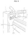
- Fig. 6 is a perspective view of operation stand
- Fig. 7 is an explanatory diagram of operation and display unit, in which (a) is an explanatory diagram of operation and display unit provided in each ink fountain device and (b) is an explanatory diagram of operation and display unit provided in the operation stand
- Fig. 8 is a control block diagram of the same
- Fig. 9 is a flowchart in zero point correction of the same.
- the ink fountain device of a printing press comprises an ink fountain roller 2 supported on right and left frames 1 to rotate.
- Weirs 3 are provided on the periphery and at both ends of the ink fountain roller 2.
- An ink fountain having a triangular section formed of a plurality of ink fountain blades 4 is arranged parallel to the longitudinal direction of the ink fountain roller 2.
- each ink fountain blade 4 is designed to move (slide) individually in a direction which permits the ink fountain blade to either be contacting with or departing from the ink fountain roller 2 by means of ink fountain blade drive device and manual position adjusting device which are described below.
- the ink fountain blade drive device is mainly composed of, as shown in Fig. 4, a stepping motor 5 (see Fig. 1) which is assembled in the ink fountain main body 5A is associated with each ink fountain blade 4.
- a screw shaft 8 is coupled to a fixing member 7, which is affixed on the ink fountain main body 5A and is linked to the output shaft of the stepping motor 5 through a gear train 6.
- An intermediate member 9 coupled to the ink fountain blade 4 is connected to the widened threaded portion at the leading end of the screw shaft 8.
- a pressure spring 12 is held by a support shaft 10 projecting from the ink fountain main body 4A.
- a support shaft 11 is incorporated in the rear part of the ink fountain blade 4. The ink fountain blade 4 is pushed by this pressure spring 12 so as to be always against the opposite side of the ink fountain roller 2, so that any excessive play in the screw coupling parts is reduced.
- the manual position adjusting device comprises, as shown in Fig. 1, a rotation knob 13 fixed to the output shaft of the stepping motor 5. The rotational force of the rotation knob 13 is transmitted to the screw shaft 8 through the gear train 6.
- the stepping motor 5 is driven and controlled by a CPU 15 as a control device (main controller) using a microprocessor and other components as is shown in Fig. 8. Its control signal is entered by way of an interface 16 and a stepping motor control driver 17.
- a detection signal (a signal indicative of the position of the ink fountain blade 4) is delivered from a rotary encoder 18 (see Fig. 1) attached to the stepping motor 5.
- the detection signal is entered in the CPU 15 by way of an interface 19 and a sensor phase counter 20.
- the CPU 15, as shown in Fig. 5 and Fig. 6, sends and receives specified signals through an input/output device 26 to and from operation and display units 25A, 25B which are provided on the front side of the ink fountain main body 4A of each ink fountain device and on an operation stand 27.
- the operation and display unit 25A on the front side of the ink fountain main body 4A of each ink fountain device includes, as shown in Fig. 7 (a), a group of indicators 30 showing the position of each ink fountain blade 4 of the ink fountain device, and a group of switches (up/down switches) 31 driving each ink fountain blade 4.
- step P1 it is judged if the zero set button 32 on the operation stand 27 is turned on or not. If it is turned on, at step P2, the positions of all ink fountain rollers 4 are read in by a detection signal from the rotary encoder 18 of the stepping motor 5.
- step P3 all of the ink fountain blades 5 which are other than at the zero position, are driven in the closing direction through the stepping motor 5.
- the positions of all ink fountain blades 4 are read in again at step P4, and the positions are shown in the indicator 30 on the front side of the ink fountain main body 4A.
- step P5 judging if all ink fountain blades 4 are at their zero positions or not, and, if at their zero positions, going to step P6, it is judged if the zero point correction start button 33 on the operation stand 27 is turned on or not. If not at their zero positions, on the other hand, returning to step P3, the ink fountain blades 4 which are at other than their zero positions are then driven in the closing direction.
- the ink fountain roller 2 is driven at a constant rotating speed at step P7, and 50%, for example, is added to the positions of all ink fountain blades 4 at step P8 and is displayed. That is, while the positions of the ink fountain blades 4 are remaining presently at the zero position, only the control display of the indicator 30 on the front side of the ink fountain main body 4A is changed to an intermediate display (for example, an indication of 50 in the display region of 0 to 100).
- an intermediate display for example, an indication of 50 in the display region of 0 to 100.
- step P9 judging if any switch is turned on, and if turned on, at step P10, it is judged if the switch (up/down switch) 31 for driving the ink fountain blades 4 on the front side of the ink fountain main body 4A is turned on or not.
- the selected ink fountain blade 5 is driven by the stepping motor 5 at step P11. This switch is manipulated while observing the opening degree of the ink fountain blade 4 on the indicator 30.
- step P12 the positions of all ink fountain blades 4 are read in, and the position adding 50% to the read-in position is shown by the indicator 30. It is then judged at step P13 if the zero point correction end button 34 on the operation stand 27 is turned on or not. On the other hand, if the switch 31 has not been turned on at step P10, it is judged if the zero point correction end button 34 is turned on or not at this step P13.
- the zero point correction end button 34 When the zero point correction end button 34 has been turned on at step P13, the positions of all ink fountain blades 4 are stored as zero positions at step P14. The positions of all ink fountain blades 4 are indicated as zero positions at step P15, and the home position adjustment operation is terminated. If the zero point correction end button 34 has not been turned on at step P13, returning to step P19, it is judged if the switch 31 is turned on or not. That is, the zero point correction operation is continued repeatedly..
- the all-increase button 35 and all-decrease button 36 if the ink film amounts of all ink fountain blades 4 are changed by nearly the same amount by the change in the type of ink or environments, it can be adjusted by a single operation of the all-increase button 35 or all-decrease button 36, instead of the operation of the individual switches (up/down switches) 31 for driving the ink fountain blades 4, so that the adjustment is done in a shorter time.
- Fig. 10 is a flowchart of a zero point correction method showing a second embodiment of the invention.
- control operation is simplified.
- the zero set button (switch) 32, the zero point correction start button (switch) 33, the zero point correction end button (switch) 34, the all-increase button (switch) 35, and the all-decrease button (switch) 36 which are provided in part of the operation and display unit 25B on the operation stand 27, may be provided on the operation and display unit 25A on the front side of the ink fountain main body 4A of each ink fountain device.
- the position of each ink fountain blade can be handled numerically when adjusting the home position, and the operation is clear and easy to understand.
- the operation is easy, and the required adjustment time is shorter.
- the position of each ink fountain blade which comprises a drive device for adjusting the position of each ink fountain blade, and a control device for controlling the drive device, positioning each ink fountain blade at its home position, setting its indication at a predetermined value, and storing the adjusted position of each ink fountain blade as a new home position while observing the indication, the position of each ink fountain blade can be handled numerically when adjusting the home position, and the operation is clear and easy to understand
- the operation is easy and the required adjustment time is shorter.
Landscapes
- Inking, Control Or Cleaning Of Printing Machines (AREA)
- Rotary Presses (AREA)
Applications Claiming Priority (2)
| Application Number | Priority Date | Filing Date | Title |
|---|---|---|---|
| JP2001009679A JP2002210921A (ja) | 2001-01-18 | 2001-01-18 | 印刷機のインキツボブレード原点位置調整方法及び装置 |
| EP02000281A EP1225047B1 (de) | 2001-01-18 | 2002-01-15 | Vorrichtung und Verfahren zum Einstellen der Referenzposition des Farbmessers in eine Druckmaschine |
Related Parent Applications (2)
| Application Number | Title | Priority Date | Filing Date |
|---|---|---|---|
| EP02000281.2 Division | 2002-01-15 | ||
| EP02000281A Division EP1225047B1 (de) | 2001-01-18 | 2002-01-15 | Vorrichtung und Verfahren zum Einstellen der Referenzposition des Farbmessers in eine Druckmaschine |
Publications (2)
| Publication Number | Publication Date |
|---|---|
| EP1844933A1 true EP1844933A1 (de) | 2007-10-17 |
| EP1844933B1 EP1844933B1 (de) | 2010-12-08 |
Family
ID=18877117
Family Applications (2)
| Application Number | Title | Priority Date | Filing Date |
|---|---|---|---|
| EP07113197A Expired - Lifetime EP1844933B1 (de) | 2001-01-18 | 2002-01-15 | Vorrichtung und Verfahren zum Einstellen der Referenzposition des Farbmessers in einer Druckmaschine |
| EP02000281A Expired - Lifetime EP1225047B1 (de) | 2001-01-18 | 2002-01-15 | Vorrichtung und Verfahren zum Einstellen der Referenzposition des Farbmessers in eine Druckmaschine |
Family Applications After (1)
| Application Number | Title | Priority Date | Filing Date |
|---|---|---|---|
| EP02000281A Expired - Lifetime EP1225047B1 (de) | 2001-01-18 | 2002-01-15 | Vorrichtung und Verfahren zum Einstellen der Referenzposition des Farbmessers in eine Druckmaschine |
Country Status (5)
| Country | Link |
|---|---|
| US (1) | US6912954B2 (de) |
| EP (2) | EP1844933B1 (de) |
| JP (1) | JP2002210921A (de) |
| AT (2) | ATE490869T1 (de) |
| DE (2) | DE60239649D1 (de) |
Families Citing this family (9)
| Publication number | Priority date | Publication date | Assignee | Title |
|---|---|---|---|---|
| US6912507B1 (en) * | 2000-08-05 | 2005-06-28 | Motorola, Inc. | Method and apparatus for interactive shopping |
| DE102006062980B3 (de) | 2005-12-12 | 2021-07-29 | Heidelberger Druckmaschinen Intellectual Property Ag & Co. Kg | Detektor zur Schließpunkterfassung im Farbkasten |
| JP2008006633A (ja) * | 2006-06-28 | 2008-01-17 | Komori Corp | 印刷機のインキツボキー位置調整方法および装置 |
| JP2009012197A (ja) * | 2007-06-29 | 2009-01-22 | Suhara Kk | 印刷装置 |
| DE102010011690A1 (de) | 2009-03-31 | 2010-11-04 | Heidelberger Druckmaschinen Ag | Vorrichtung zur Nullpunktjustierung |
| DE102011006521B4 (de) | 2011-03-31 | 2013-09-19 | Koenig & Bauer Aktiengesellschaft | System zum Einstellen eines Farbflusses an einer Zone eines Farbwerks |
| DE102011006526B4 (de) | 2011-03-31 | 2013-09-19 | Koenig & Bauer Aktiengesellschaft | System zum Einstellen eines Farbflusses an Zonen eines Farbwerks |
| DE102011006522B4 (de) | 2011-03-31 | 2013-06-06 | Koenig & Bauer Aktiengesellschaft | Verfahren zum Einstellen eines Farbflusses an einer Zone eines Farbwerks |
| CN108819479B (zh) * | 2018-09-19 | 2024-04-19 | 江苏华宇印涂设备集团有限公司 | 一种电动墨斗系统 |
Citations (5)
| Publication number | Priority date | Publication date | Assignee | Title |
|---|---|---|---|---|
| US4581994A (en) | 1983-07-11 | 1986-04-15 | M.A.N.-Roland Druckmaschinen Aktiengesellschaft | Ink metering device for a printing press |
| US4703691A (en) | 1982-12-21 | 1987-11-03 | Dai Nippon Insatsu Kabushiki Kaisha | Method for adjusting an ink fountain in a printing press and ink fountains |
| US4803923A (en) * | 1986-12-29 | 1989-02-14 | Dai Nippon Printing Co., Ltd. | Ink blade adjusting system with zero point memory |
| US5138944A (en) | 1991-09-03 | 1992-08-18 | Heidelberg Harris Inc. | Method and apparatus for setting respective positions of ink keys |
| JPH0796293A (ja) | 1992-08-05 | 1995-04-11 | Akihisa Ueda | 微生物による汚水浄化処理に、籾殻を処理して製造した活性炭を使用する方法。 |
Family Cites Families (18)
| Publication number | Priority date | Publication date | Assignee | Title |
|---|---|---|---|---|
| US3134325A (en) * | 1962-01-16 | 1964-05-26 | Wood Newspaper Mach Corp | Ink adjusting mechanism |
| US3702587A (en) * | 1970-10-12 | 1972-11-14 | North American Rockwell | Electronic control system for adjustment of ink fountain in a printing press |
| US3792659A (en) * | 1971-08-16 | 1974-02-19 | Hantscho G Co Inc | Multiple point ink control apparatus for printing presses |
| US4008664A (en) * | 1973-07-23 | 1977-02-22 | Harris-Intertype Corporation | Ink key control system |
| US3930447A (en) * | 1974-07-22 | 1976-01-06 | Harris Corporation | Dual purpose display for printing presses |
| US4193345A (en) * | 1977-04-01 | 1980-03-18 | Roland Offsetmaschinenfabrik Faber & Schleicher Ag | Device for adjustment of the ink flow on printing press inking units |
| JPS58136448A (ja) * | 1982-02-08 | 1983-08-13 | Toshiba Mach Co Ltd | インキ供給量調整機構の調整位置表示装置 |
| JPS58219064A (ja) * | 1982-11-16 | 1983-12-20 | Hoomen Kogyo Kk | 印刷機のインキ量調整装置 |
| JPS60117143U (ja) * | 1984-01-14 | 1985-08-08 | ジエ−ピ−イ−株式会社 | オフセツト印刷機に於けるインク壷装置 |
| JP2524114B2 (ja) * | 1985-05-09 | 1996-08-14 | グラフイクス・マイクロシステムズ・インク | 印刷装置のインキ制御装置 |
| JPS61291139A (ja) * | 1985-06-20 | 1986-12-20 | Dainippon Printing Co Ltd | オフセツト印刷におけるインキ壷の初期設定方法および初期設定装置 |
| US4969395A (en) | 1987-03-09 | 1990-11-13 | Toshiba Kikai Kabushiki Kaisha | Inking apparatus for use in printing machines |
| JP2667397B2 (ja) * | 1987-03-31 | 1997-10-27 | 東芝機械株式会社 | 印刷機におけるインキ調整板開度表示装置 |
| JP3264047B2 (ja) * | 1993-06-30 | 2002-03-11 | 凸版印刷株式会社 | インキ供給量設定装置 |
| JPH0747659A (ja) * | 1993-08-06 | 1995-02-21 | Toppan Printing Co Ltd | 印刷機のインキキー開度値補正装置 |
| US5832830A (en) * | 1995-01-10 | 1998-11-10 | Heidelberger Druckmaschinen Ag | Method and apparatus for normalizing the display of ink key zero points in an ink fountain |
| DE19535193A1 (de) | 1995-09-22 | 1997-03-27 | Kba Planeta Ag | Verfahren und Einrichtung zur Meßwertkonvertierung |
| JP2001009679A (ja) | 1999-07-02 | 2001-01-16 | Horiba Ltd | 生産ラインにおけるデータ管理システム |
-
2001
- 2001-01-18 JP JP2001009679A patent/JP2002210921A/ja active Pending
-
2002
- 2002-01-10 US US10/041,498 patent/US6912954B2/en not_active Expired - Fee Related
- 2002-01-15 EP EP07113197A patent/EP1844933B1/de not_active Expired - Lifetime
- 2002-01-15 DE DE60239649T patent/DE60239649D1/de not_active Expired - Lifetime
- 2002-01-15 AT AT07113197T patent/ATE490869T1/de not_active IP Right Cessation
- 2002-01-15 AT AT02000281T patent/ATE504445T1/de not_active IP Right Cessation
- 2002-01-15 EP EP02000281A patent/EP1225047B1/de not_active Expired - Lifetime
- 2002-01-15 DE DE60238566T patent/DE60238566D1/de not_active Expired - Lifetime
Patent Citations (5)
| Publication number | Priority date | Publication date | Assignee | Title |
|---|---|---|---|---|
| US4703691A (en) | 1982-12-21 | 1987-11-03 | Dai Nippon Insatsu Kabushiki Kaisha | Method for adjusting an ink fountain in a printing press and ink fountains |
| US4581994A (en) | 1983-07-11 | 1986-04-15 | M.A.N.-Roland Druckmaschinen Aktiengesellschaft | Ink metering device for a printing press |
| US4803923A (en) * | 1986-12-29 | 1989-02-14 | Dai Nippon Printing Co., Ltd. | Ink blade adjusting system with zero point memory |
| US5138944A (en) | 1991-09-03 | 1992-08-18 | Heidelberg Harris Inc. | Method and apparatus for setting respective positions of ink keys |
| JPH0796293A (ja) | 1992-08-05 | 1995-04-11 | Akihisa Ueda | 微生物による汚水浄化処理に、籾殻を処理して製造した活性炭を使用する方法。 |
Also Published As
| Publication number | Publication date |
|---|---|
| ATE504445T1 (de) | 2011-04-15 |
| EP1225047A1 (de) | 2002-07-24 |
| US20020056385A1 (en) | 2002-05-16 |
| EP1225047B1 (de) | 2011-04-06 |
| EP1844933B1 (de) | 2010-12-08 |
| DE60239649D1 (de) | 2011-05-19 |
| JP2002210921A (ja) | 2002-07-31 |
| DE60238566D1 (de) | 2011-01-20 |
| US6912954B2 (en) | 2005-07-05 |
| ATE490869T1 (de) | 2010-12-15 |
Similar Documents
| Publication | Publication Date | Title |
|---|---|---|
| EP0364262B1 (de) | Drucker mit Vorrichtung zum Einstellen der Schlagweite des Kopfes | |
| US5570633A (en) | Automated printing press with reinsertion registration control | |
| EP1225047B1 (de) | Vorrichtung und Verfahren zum Einstellen der Referenzposition des Farbmessers in eine Druckmaschine | |
| JPH0454581B2 (de) | ||
| JPH05246014A (ja) | インキキーの位置設定方法および装置 | |
| JPH0358913B2 (de) | ||
| JPS63168359A (ja) | 印刷機のインク供給量調整装置 | |
| US7222569B2 (en) | Oscillation amount adjusting device for oscillating roller | |
| JP4372326B2 (ja) | 印刷機のインキツボキー原点位置調整方法及び装置 | |
| JPH03118175A (ja) | ヘッドギャップ調整機能を備えた印字装置 | |
| US5233920A (en) | Image adjusting device for offset printing machine | |
| JP2000006478A (ja) | 紙送り制御方法および記録装置 | |
| JPS6232110B2 (de) | ||
| JPS62130854A (ja) | 見当プリセツト装置 | |
| JP2009012197A (ja) | 印刷装置 | |
| JPH0669812B2 (ja) | ラベルフイ−ド量の調整装置 | |
| JP2652836B2 (ja) | 印刷装置のインキ制御装置 | |
| JPS59218860A (ja) | 印刷機のコンペンプリセツト装置 | |
| JPH08174801A (ja) | オフセット印刷機のローラニップ量調整装置 | |
| JPH02258380A (ja) | プリンタ | |
| JP2000108431A (ja) | 紙送り制御方法および記録装置 | |
| JP2001038999A (ja) | 孔版印刷機 | |
| JPH03169665A (ja) | プラテンギャップ調整装置 | |
| JPH04163074A (ja) | ドットプリンタ | |
| JP2000062147A (ja) | インキキーの制御方法およびその装置 |
Legal Events
| Date | Code | Title | Description |
|---|---|---|---|
| PUAI | Public reference made under article 153(3) epc to a published international application that has entered the european phase |
Free format text: ORIGINAL CODE: 0009012 |
|
| AC | Divisional application: reference to earlier application |
Ref document number: 1225047 Country of ref document: EP Kind code of ref document: P |
|
| AK | Designated contracting states |
Kind code of ref document: A1 Designated state(s): AT BE CH CY DE DK ES FI FR GB GR IE IT LI LU MC NL PT SE TR |
|
| 17P | Request for examination filed |
Effective date: 20080415 |
|
| AKX | Designation fees paid |
Designated state(s): AT BE CH CY DE DK ES FI FR GB GR IE IT LI LU MC NL PT SE TR |
|
| 17Q | First examination report despatched |
Effective date: 20080610 |
|
| APBK | Appeal reference recorded |
Free format text: ORIGINAL CODE: EPIDOSNREFNE |
|
| APBN | Date of receipt of notice of appeal recorded |
Free format text: ORIGINAL CODE: EPIDOSNNOA2E |
|
| APBR | Date of receipt of statement of grounds of appeal recorded |
Free format text: ORIGINAL CODE: EPIDOSNNOA3E |
|
| APBV | Interlocutory revision of appeal recorded |
Free format text: ORIGINAL CODE: EPIDOSNIRAPE |
|
| GRAP | Despatch of communication of intention to grant a patent |
Free format text: ORIGINAL CODE: EPIDOSNIGR1 |
|
| GRAJ | Information related to disapproval of communication of intention to grant by the applicant or resumption of examination proceedings by the epo deleted |
Free format text: ORIGINAL CODE: EPIDOSDIGR1 |
|
| GRAP | Despatch of communication of intention to grant a patent |
Free format text: ORIGINAL CODE: EPIDOSNIGR1 |
|
| GRAS | Grant fee paid |
Free format text: ORIGINAL CODE: EPIDOSNIGR3 |
|
| GRAA | (expected) grant |
Free format text: ORIGINAL CODE: 0009210 |
|
| AC | Divisional application: reference to earlier application |
Ref document number: 1225047 Country of ref document: EP Kind code of ref document: P |
|
| AK | Designated contracting states |
Kind code of ref document: B1 Designated state(s): AT BE CH CY DE DK ES FI FR GB GR IE IT LI LU MC NL PT SE TR |
|
| REG | Reference to a national code |
Ref country code: GB Ref legal event code: FG4D |
|
| REG | Reference to a national code |
Ref country code: CH Ref legal event code: EP |
|
| REG | Reference to a national code |
Ref country code: IE Ref legal event code: FG4D |
|
| REF | Corresponds to: |
Ref document number: 60238566 Country of ref document: DE Date of ref document: 20110120 Kind code of ref document: P |
|
| REG | Reference to a national code |
Ref country code: SE Ref legal event code: TRGR |
|
| REG | Reference to a national code |
Ref country code: NL Ref legal event code: VDEP Effective date: 20101208 |
|
| PG25 | Lapsed in a contracting state [announced via postgrant information from national office to epo] |
Ref country code: FI Free format text: LAPSE BECAUSE OF FAILURE TO SUBMIT A TRANSLATION OF THE DESCRIPTION OR TO PAY THE FEE WITHIN THE PRESCRIBED TIME-LIMIT Effective date: 20101208 Ref country code: AT Free format text: LAPSE BECAUSE OF FAILURE TO SUBMIT A TRANSLATION OF THE DESCRIPTION OR TO PAY THE FEE WITHIN THE PRESCRIBED TIME-LIMIT Effective date: 20101208 Ref country code: CY Free format text: LAPSE BECAUSE OF FAILURE TO SUBMIT A TRANSLATION OF THE DESCRIPTION OR TO PAY THE FEE WITHIN THE PRESCRIBED TIME-LIMIT Effective date: 20101208 Ref country code: NL Free format text: LAPSE BECAUSE OF FAILURE TO SUBMIT A TRANSLATION OF THE DESCRIPTION OR TO PAY THE FEE WITHIN THE PRESCRIBED TIME-LIMIT Effective date: 20101208 |
|
| PGFP | Annual fee paid to national office [announced via postgrant information from national office to epo] |
Ref country code: DE Payment date: 20110112 Year of fee payment: 10 |
|
| PG25 | Lapsed in a contracting state [announced via postgrant information from national office to epo] |
Ref country code: ES Free format text: LAPSE BECAUSE OF FAILURE TO SUBMIT A TRANSLATION OF THE DESCRIPTION OR TO PAY THE FEE WITHIN THE PRESCRIBED TIME-LIMIT Effective date: 20110319 Ref country code: BE Free format text: LAPSE BECAUSE OF FAILURE TO SUBMIT A TRANSLATION OF THE DESCRIPTION OR TO PAY THE FEE WITHIN THE PRESCRIBED TIME-LIMIT Effective date: 20101208 Ref country code: GR Free format text: LAPSE BECAUSE OF FAILURE TO SUBMIT A TRANSLATION OF THE DESCRIPTION OR TO PAY THE FEE WITHIN THE PRESCRIBED TIME-LIMIT Effective date: 20110309 Ref country code: PT Free format text: LAPSE BECAUSE OF FAILURE TO SUBMIT A TRANSLATION OF THE DESCRIPTION OR TO PAY THE FEE WITHIN THE PRESCRIBED TIME-LIMIT Effective date: 20110408 |
|
| PG25 | Lapsed in a contracting state [announced via postgrant information from national office to epo] |
Ref country code: MC Free format text: LAPSE BECAUSE OF NON-PAYMENT OF DUE FEES Effective date: 20110131 |
|
| REG | Reference to a national code |
Ref country code: CH Ref legal event code: PL |
|
| REG | Reference to a national code |
Ref country code: SE Ref legal event code: EUG |
|
| PLBE | No opposition filed within time limit |
Free format text: ORIGINAL CODE: 0009261 |
|
| REG | Reference to a national code |
Ref country code: FR Ref legal event code: ST Effective date: 20110930 |
|
| STAA | Information on the status of an ep patent application or granted ep patent |
Free format text: STATUS: NO OPPOSITION FILED WITHIN TIME LIMIT |
|
| REG | Reference to a national code |
Ref country code: IE Ref legal event code: MM4A |
|
| PG25 | Lapsed in a contracting state [announced via postgrant information from national office to epo] |
Ref country code: FR Free format text: LAPSE BECAUSE OF NON-PAYMENT OF DUE FEES Effective date: 20110208 Ref country code: LI Free format text: LAPSE BECAUSE OF NON-PAYMENT OF DUE FEES Effective date: 20110131 Ref country code: CH Free format text: LAPSE BECAUSE OF NON-PAYMENT OF DUE FEES Effective date: 20110131 Ref country code: DK Free format text: LAPSE BECAUSE OF FAILURE TO SUBMIT A TRANSLATION OF THE DESCRIPTION OR TO PAY THE FEE WITHIN THE PRESCRIBED TIME-LIMIT Effective date: 20101208 |
|
| 26N | No opposition filed |
Effective date: 20110909 |
|
| GBPC | Gb: european patent ceased through non-payment of renewal fee |
Effective date: 20110308 |
|
| PG25 | Lapsed in a contracting state [announced via postgrant information from national office to epo] |
Ref country code: IT Free format text: LAPSE BECAUSE OF FAILURE TO SUBMIT A TRANSLATION OF THE DESCRIPTION OR TO PAY THE FEE WITHIN THE PRESCRIBED TIME-LIMIT Effective date: 20101208 |
|
| REG | Reference to a national code |
Ref country code: DE Ref legal event code: R097 Ref document number: 60238566 Country of ref document: DE Effective date: 20110909 |
|
| PG25 | Lapsed in a contracting state [announced via postgrant information from national office to epo] |
Ref country code: IE Free format text: LAPSE BECAUSE OF NON-PAYMENT OF DUE FEES Effective date: 20110115 |
|
| PG25 | Lapsed in a contracting state [announced via postgrant information from national office to epo] |
Ref country code: GB Free format text: LAPSE BECAUSE OF NON-PAYMENT OF DUE FEES Effective date: 20110308 |
|
| PG25 | Lapsed in a contracting state [announced via postgrant information from national office to epo] |
Ref country code: DE Free format text: LAPSE BECAUSE OF NON-PAYMENT OF DUE FEES Effective date: 20120801 |
|
| REG | Reference to a national code |
Ref country code: DE Ref legal event code: R119 Ref document number: 60238566 Country of ref document: DE Effective date: 20120801 |
|
| PG25 | Lapsed in a contracting state [announced via postgrant information from national office to epo] |
Ref country code: SE Free format text: LAPSE BECAUSE OF NON-PAYMENT OF DUE FEES Effective date: 20110116 |
|
| PG25 | Lapsed in a contracting state [announced via postgrant information from national office to epo] |
Ref country code: LU Free format text: LAPSE BECAUSE OF NON-PAYMENT OF DUE FEES Effective date: 20110115 |
|
| PG25 | Lapsed in a contracting state [announced via postgrant information from national office to epo] |
Ref country code: TR Free format text: LAPSE BECAUSE OF FAILURE TO SUBMIT A TRANSLATION OF THE DESCRIPTION OR TO PAY THE FEE WITHIN THE PRESCRIBED TIME-LIMIT Effective date: 20101208 |