EP1845189B1 - Procédé destiné à la commande de la température des éléments céramiques d'une barre d'appui ou d'une racleuse dans une installation de production de papier tout comme dispositif et barre d'appui ou racleuse destinés à l'exécution de ce procédé - Google Patents
Procédé destiné à la commande de la température des éléments céramiques d'une barre d'appui ou d'une racleuse dans une installation de production de papier tout comme dispositif et barre d'appui ou racleuse destinés à l'exécution de ce procédé Download PDFInfo
- Publication number
- EP1845189B1 EP1845189B1 EP06450181A EP06450181A EP1845189B1 EP 1845189 B1 EP1845189 B1 EP 1845189B1 EP 06450181 A EP06450181 A EP 06450181A EP 06450181 A EP06450181 A EP 06450181A EP 1845189 B1 EP1845189 B1 EP 1845189B1
- Authority
- EP
- European Patent Office
- Prior art keywords
- supporting
- scraper bar
- carrier medium
- channel
- temperature
- Prior art date
- Legal status (The legal status is an assumption and is not a legal conclusion. Google has not performed a legal analysis and makes no representation as to the accuracy of the status listed.)
- Not-in-force
Links
Images


Classifications
-
- D—TEXTILES; PAPER
- D21—PAPER-MAKING; PRODUCTION OF CELLULOSE
- D21F—PAPER-MAKING MACHINES; METHODS OF PRODUCING PAPER THEREON
- D21F1/00—Wet end of machines for making continuous webs of paper
- D21F1/48—Suction apparatus
- D21F1/483—Drainage foils and bars
Definitions
- the subject invention relates to a method for controlling the temperature of the ceramic elements of a support or squeegee, which is assigned in a plant for paper production to the located therein at least one screen belt or at least one felt belt. Furthermore, the invention relates to a device and a support or squeegee for performing this method.
- Equipment for paper production have at least one screen belt and further at least one felt belt, which are assigned to the two bands in their direction of succession, aligned transversely to the bands supporting strips over which the screen belt and the felt belt are guided.
- the support strips In a first area of the paper-making plant, the support strips also serve as squeegee strips for the liquids emerging from the paper pulp and passing through the sieve belt. Since these Abstützorgn are exposed to large mechanical and corrosive loads, there is a need to provide these on their the Siebb Sn or the felt tapes facing surfaces with plates of a ceramic material to which the screen belt or the felt belt to the plant.
- the screen belt or the felt belt at very high speeds of e.g. Moved 40 m / sec over the Abstützorgn away.
- the support strips means for sucking the emerging from the pulp liquids or for sucking air to dry the paper belt resting on the wire belt or for drying the felt belt, whereby the wire belt or the felt on the support bars with very high pressure rest. As a result, frictional forces occur, by which the ceramic elements can be heated strongly.
- the support strips cool down to the ambient temperature.
- the paper pulp is sprayed onto the sieve belt, which can have a temperature of up to 90 °.
- a steam hood can be provided, within which superheated steam is located, which serves to dry the paper tape and through which the ceramic elements can be subjected to temperatures up to 150 ° C. It should also be noted that the ceramic elements of the support or squeegee have a very low thermal conductivity.
- the ceramic elements of the supporting or wiper strips are subject to very high thermal stresses, which can change within a very short time within a range of about 200 ° C.
- This control of the operation of the system is characterized in that the support or wiper blades are assigned spray nozzles through which water is sprayed onto the support or squeegee, and that the trained with Abstütz- or squeegee suction boxes are provided with vacuum lines through which of the pressure with which the screen belts abut against the support or wiper strips, can be controlled.
- the subject invention is therefore based on the object to provide a method by which the individual located in a plant for paper production support or squeegee can be protected from being damaged due to occurring in these thermal stresses.
- this will According to the invention achieved in that the support or squeegee is formed with at least one channel through which a carrier medium for heat or for cold is passed.
- a mixing valve is provided in the line leading to the at least one channel, are connected to which lines for carrier media for heat or for cold and which is set to the temperature which should have the respective support or squeegee ,
- a temperature sensor may be provided in the leading away from the support or squeegee line, by which the temperature of the effluent from the supporting or squeegee carrier medium is measured.
- a temperature sensor can also be provided in the line leading to the support or stripping bar, by means of which the temperature of the support medium flowing toward the support or stripping bar is measured.
- the temperature of the carrier medium flowing in toward the support strip or scraper blade is controlled as a function of the temperature of the carrier medium flowing away from it.
- the carrier medium can be conveyed by means of a feed pump in a self-contained line circuit.
- the carrier medium flowing away from the supporting or wiper strip can either be conducted via a heating device or via a cooling device, and then the support or wiper strip can be supplied.
- the heating device or the cooling device can be controlled as a function of the temperature of the carrier medium flowing away from the supporting or wiping strip.
- the power of the feed pump can be controlled as a function of the temperature of the carrier medium flowing away from the support strip or scraper blade.
- both the performance of the heating device or of the cooling device and the power of the feed pump can be controlled as a function of the temperature of the carrier medium flowing away from the support or wiper strip.
- the carrier medium is passed continuously through the supporting or stripping bar, wherein it is in particular passed through the ceramic elements of the supporting or stripping bar.
- the support or squeegee is formed with at least one channel, are connected to which lines for the support or squeegee inflowing carrier medium and for this flowing from the carrier medium.
- a mixing valve for carrier media of heat and cold is located in the line leading to the at least one channel.
- a temperature sensor may be located in the line leading to the support or stripping bar and / or in the line leading away from the support or stiffening bar.
- a line system in which there are a feed pump, a heater and a cooling device for the carrier medium, wherein at least one temperature sensor for determining the temperature of the effluent from the support or squeegee carrier medium and a control unit for controlling the Benefits of the heater and the cooling device and or or the feed pump are provided.
- at least one temperature sensor for determining the temperature of the supporting or stripping bar supplied carrier medium may be provided.
- An inventive support or squeegee for carrying out this method is formed with at least one channel for conducting a carrier medium for heat or for cold.
- the channel can pass through the ceramic elements.
- the channel can be located between the ceramic elements and a carrier strip for the ceramic elements.
- the channel may begin at one end of the support strip and terminate at the other end thereof, or the channel may begin at one end of the support strip and be returned thereto to the same end.
- the leading channel can be connected to the returning channel within the support or squeegee.
- the leading channel can be connected to the returning channel via a piece of pipe located outside the support or wiper strip.
- both the ceramic elements and the carrier strip can be formed with at least one channel or channel pieces.
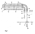
- the supporting or stripping strip 1 consists of a carrier strip 1a with ceramic elements 1b fastened thereto, wherein the supporting or stripping strip 1 is formed with two channels 11 and 12. At one end of the support or squeegee 1 close to the mouths of the two channels 11 and 12 connecting pipes 13 and 14 at. At the other end of the support or
- the two channels 11 and 12 are connected to each other by means of a piece of pipe 15.
- the output line 23 of a mixing valve 2 is connected, which is supplied via a first connecting line 21, a carrier medium for cold and a second connecting line 22, a carrier medium for heat.
- a control device 20 the temperature of the dispensed from the mixing valve 2 via the output line 23 carrier medium is set to that value, which temperature value that support or stripping 1 in the system should have, which is fed via the mixing valve 2 with carrier medium.
- a support or stripping strip 1 located in a certain area of the installation should have. Then the mixing valve 2 is set to this temperature. As a result, this strip 1 is brought to the desired temperature by means of the supporting or stripping 1 via the output line 23 of the mixing valve 2 supplied carrier medium. The effluent from the support or squeegee 1 via the pipe 14, heated or cooled by this carrier medium is discharged via a further line 24 either in a memory or in the channel.
- temperature sensors 25 and 26 are further provided, by means of which the temperatures of the carrier medium flowing through these lines are detected.
- the temperature of the respective support or stripping bar 1 can be brought approximately to the desired value in the rule.
- the support or squeegee 1 is associated with a self-contained line circuit 3 for a carrier medium for heat or cold, in which a memory 30 for the carrier medium, a feed pump 4, a control valve 5, a heater 6 and a cooling device 7 are located. Furthermore, a control unit 8 is provided, which are assigned to two located in the line circuit 3 temperature sensors 81 and 82 and which serve to control the feed pump 4, the control valve 5, the heater 6 and the cooling device 7.
- temperature sensor 81 located in the line 35 takes place a temperature measurement of the support or stripping 1 inflowing carrier medium and by means of located in the line 36 temperature sensor 82 is a temperature measurement of the effluent from the stripping or scraper 1 medium.
- the measured values output by the temperature sensors 81 and 82 are transmitted via control lines 83 and 84 to the control unit 8, by means of which the feed pump 4, the control valve 5, the heating device 6 and the cooling device 7 are controlled via control lines 85, 86, 87 and 88.
- the control valve 5 is redirected to the effect that the carrier medium is supplied by means of the feed pump 4 of the heater 6, in which it is heated, whereupon it is passed via the connecting pipe 13 into the channel 11. This procedure is maintained until the support or squeegee 1 has the required temperature for the particular operating case. Soferne contrast, it is determined by the control unit 8 that the existing in the support or stripping 1 temperature must be reduced, the control valve 5 is redirected to the effect that the carrier medium is fed by means of the pump 4 of the cooling device 7, in which it is cooled , whereupon it is also passed via the connecting pipe 13 into the channel 11. This procedure is also maintained until the support or squeegee 1 has the required temperature for the particular operating case.
- a further control with regard to the heating or cooling of the supporting or stripping strip 1 can also take place in that the power of the conveying pump 4 is increased or decreased by the control unit 8.
- Soferne in operation of a plant for paper production by one of the support or squeegee 1 associated control unit 8 is determined that this support or squeegee 1 has a too low or too high temperature for the relevant operating case or too rapid a change in temperature this support or stripping 1 takes place, whereby in each case there is the risk of cracking or fractures of the ceramic elements 1 b of this support or stripping 1, this support or stripping 1 is supplied according to heated or cooled support medium, whereby the ceramic Elements 1b are not exposed to unacceptable thermal loads, thereby preventing damage caused thereby.
- Fig. 10, 10a and 10b Several embodiments of support or squeegee 1 are shown, which consist of support strips 1a with attached to these plates 1b made of ceramic material and which are formed with channels 11 and 12, which enforce this support or squeegee 1 in the longitudinal direction. These channels can begin at one end of the support or squeegee 1 and end at the other end of the strips 1. Alternatively, these channels may begin at one end of the squeegee 1 and be returned to that end. Furthermore, these channels can pass through the ceramic plates 1 b or be provided in the support bar 1 a or be located between the ceramic plates 1 b and the support bar 1 a. Furthermore, the channels may be formed with different cross sections.
- the arrangement of the channels within the support or squeegee or the formation of the cross section is of crucial importance to ensure that the targeted by the carrier medium flowing through this Temperature of the plates 1 b made of ceramic material is achieved in order to avoid their damage by thermal stresses.
- a carrier medium for cold or for heat in particular water is used as a carrier medium for cold or for heat in particular water.
Landscapes
- Paper (AREA)
- Tunnel Furnaces (AREA)
- Devices For Post-Treatments, Processing, Supply, Discharge, And Other Processes (AREA)
- Control Of Steam Boilers And Waste-Gas Boilers (AREA)
- Belt Conveyors (AREA)
- Re-Forming, After-Treatment, Cutting And Transporting Of Glass Products (AREA)
Claims (25)
- Procédé pour commander la température des éléments céramiques (1b) d'une barre d'appui ou racleuse (1) qui est associée, dans une installation de production de papier, à au moins une bande de tamis située dans celle-ci ou à au moins une bande de feutre, caractérisé en ce que la barre d'appui ou racleuse (1) est pourvue d'au moins un conduit (11, 12) par lequel passe un agent porteur pour la chaleur ou le froid.
- Procédé selon la revendication 1, caractérisé en ce qu'il est prévu dans la conduite qui mène audit conduit (11, 12) un régulateur à vannes (2) auquel sont raccordées les conduites (21, 22) pour les agents porteurs pour la chaleur ou pour le froid et qui est réglé à la température que doit présenter la barre d'appui ou racleuse (1) concernée.
- Procédé selon l'une des revendications 1 et 2, caractérisé en ce qu'il est prévu dans la conduite (26) qui part de la barre d'appui ou racleuse (1) un capteur de température (15) grâce auquel la température de l'agent porteur sortant de ladite barre d'appui ou racleuse (1) est mesurée.
- Procédé selon l'une des revendications 1 à 3, caractérisé en ce qu'il est prévu dans la conduite (23) menant à la barre d'appui ou racleuse (1) un capteur de température (25) grâce auquel la température de l'agent porteur s'écoulant vers ladite barre d'appui ou racleuse (1) est mesurée.
- Procédé selon la revendication 1, caractérisé en ce que la température de l'agent porteur qui s'écoule vers la barre d'appui ou racleuse (1) est commandée en fonction de la température de l'agent porteur qui sort de celle-ci.
- Procédé selon la revendication 5, caractérisé en ce que l'agent porteur est acheminé à l'aide d'une pompe d'alimentation (4) dans un circuit fermé (3).
- Procédé selon l'une des revendications 5 et 6, caractérisé en ce que l'agent porteur qui sort de la barre d'appui ou racleuse (1) passe par un dispositif de chauffage (6) ou par un dispositif de refroidissement (7), puis est amené dans la barre d'appui ou racleuse (1).
- Procédé selon la revendication 7, caractérisé en ce que le dispositif de chauffage (6) ou le dispositif de refroidissement (7) est commandé en fonction de la température de l'agent porteur qui sort de la barre d'appui ou racleuse (1).
- Procédé selon la revendication 7, caractérisé en ce que la puissance de la pompe d'alimentation (4) est commandée en fonction de la température de l'agent porteur qui sort de la barre d'appui ou racleuse (1).
- Procédé selon la revendication 7, caractérisé en ce que la puissance du dispositif de chauffage (6) ou du dispositif de refroidissement (7) et la puissance de la pompe d'alimentation (4) sont commandées en fonction de la température de l'agent porteur qui sort de la barre d'appui ou racleuse (1).
- Procédé selon l'une des revendications 1 à 10, caractérisé en ce que l'agent porteur traverse en continu la barre d'appui ou racleuse (1).
- Procédé selon l'une des revendications 1 à 11, caractérisé en ce que l'agent porteur traverse en continu les éléments céramiques (1b) de la barre d'appui ou racleuse (1).
- Installation pour la mise en oeuvre du procédé selon l'une des revendications 1 à 12, caractérisée en ce que la barre d'appui ou racleuse (1) est pourvue d'au moins un conduit (11, 12) auquel sont raccordées une conduite (13) pour un agent porteur arrivant dans la barre d'appui ou racleuse (1) et une conduite (14) pour un agent porteur sortant de celle-ci.
- Installation selon la revendication 13, caractérisée en ce qu'un régulateur à vannes (2) pour les agents porteurs de chaleur et de froid se trouve dans la conduite (23) qui mène audit conduit (11, 12).
- Installation selon la revendication 14, caractérisée en ce qu'un capteur de température (25, 26) se trouve dans la conduite (23) qui mène à la barre d'appui ou racleuse (1) et/ou dans la conduite (24) qui part de celle-ci.
- Installation selon la revendication 13, caractérisée en ce qu'il est prévu un système de conduites (3) dans lequel se trouvent une pompe d'alimentation (4) pour l'agent porteur, un dispositif de chauffage (6) et un dispositif de refroidissement (7) pour l'agent porteur, et en ce qu'il est également prévu au moins un capteur de température (82) pour déterminer la température de l'agent porteur qui sort de la barre d'appui ou racleuse (1) et une unité de commande (8) pour commander la puissance du dispositif de chauffage (6) et du dispositif de refroidissement (7) et/ou de la pompe d'alimentation (4).
- Installation selon la revendication 16, caractérisée en ce qu'il est également prévu au moins un capteur de température (81) pour déterminer la température de l'agent porteur amené dans la barre d'appui ou racleuse (1).
- Barre d'appui ou racleuse (1) pour la mise en oeuvre du procédé selon l'une des revendications 1 à 12 ou pour une installation selon l'une des revendications 13 à 17, caractérisée en ce qu'elle est pourvue d'au moins un conduit (11, 12) pour le passage d'un agent porteur pour la chaleur ou pour le froid.
- Barre d'appui ou racleuse (1) selon la revendication 18, caractérisée en ce que le conduit (11) traverse les éléments céramiques (1b).
- Barre d'appui ou racleuse (1) selon la revendication 18, caractérisée en ce que le conduit se trouve entre les éléments céramiques (1b) et une barre de support (la) pour les éléments céramiques (1b).
- Barre d'appui ou racleuse (1) selon l'une des revendications 18 à 20, caractérisée en ce que le conduit commence à une extrémité de la barre d'appui ou racleuse (1) et se termine à l'autre extrémité de celle-ci.
- Barre d'appui ou racleuse (1) selon l'une des revendications 18 à 20, caractérisée en ce que le conduit commence à une extrémité de la barre d'appui ou racleuse (1) et revient dans celle-ci à la même extrémité.
- Barre d'appui ou racleuse (1) selon la revendication 22, caractérisée en ce que le conduit d'aller (11) est relié au conduit de retour (12) à l'intérieur de ladite barre d'appui ou racleuse (1).
- Barre d'appui ou racleuse (1) selon la revendication 22, caractérisée en ce que le conduit d'aller (11) est relié au conduit de retour (12) par une pièce tubulaire (15) qui se trouve à l'extérieur de ladite barre d'appui ou racleuse (1).
- Barre d'appui ou racleuse (1) selon l'une des revendication 18 à 24, caractérisée en ce que les éléments céramiques (1b) et la barre de support (la) sont tous pourvus d'au moins un conduit ou d'éléments formant conduits.
Priority Applications (1)
| Application Number | Priority Date | Filing Date | Title |
|---|---|---|---|
| AT06450181T ATE434682T1 (de) | 2006-04-13 | 2006-12-14 | Verfahren zur steuerung der temperatur der keramischen elemente einer abstütz- bzw. abstreifleiste in einer anlage zur papiererzeugung sowie einrichtung und abstütz- bzw. abstreifleiste zur durchführung dieses verfahrens |
Applications Claiming Priority (1)
| Application Number | Priority Date | Filing Date | Title |
|---|---|---|---|
| AT0064406A AT503404A1 (de) | 2006-04-13 | 2006-04-13 | Verfahren zur steuerung der temperatur der keramischen elemente einer abstütz- bzw. abstreifleiste in einer anlage zur papiererzeugung sowie einrichtung und abstütz- bzw. abstreifleiste zur durchführung dieses verfahrens |
Publications (3)
| Publication Number | Publication Date |
|---|---|
| EP1845189A2 EP1845189A2 (fr) | 2007-10-17 |
| EP1845189A3 EP1845189A3 (fr) | 2008-04-30 |
| EP1845189B1 true EP1845189B1 (fr) | 2009-06-24 |
Family
ID=38283059
Family Applications (1)
| Application Number | Title | Priority Date | Filing Date |
|---|---|---|---|
| EP06450181A Not-in-force EP1845189B1 (fr) | 2006-04-13 | 2006-12-14 | Procédé destiné à la commande de la température des éléments céramiques d'une barre d'appui ou d'une racleuse dans une installation de production de papier tout comme dispositif et barre d'appui ou racleuse destinés à l'exécution de ce procédé |
Country Status (9)
| Country | Link |
|---|---|
| US (1) | US7550062B2 (fr) |
| EP (1) | EP1845189B1 (fr) |
| JP (1) | JP4859736B2 (fr) |
| CN (1) | CN101054780B (fr) |
| AT (2) | AT503404A1 (fr) |
| BR (1) | BRPI0701985A (fr) |
| CA (1) | CA2582017C (fr) |
| DE (1) | DE502006004060D1 (fr) |
| ES (1) | ES2326385T3 (fr) |
Families Citing this family (2)
| Publication number | Priority date | Publication date | Assignee | Title |
|---|---|---|---|---|
| TWI686524B (zh) * | 2016-12-13 | 2020-03-01 | 財團法人紡織產業綜合研究所 | 紡織設備與其熱能調控方法 |
| CN115681979B (zh) * | 2022-09-28 | 2025-11-18 | 江西仙廷精藏设备有限公司 | 一种火化机操作面降温装置 |
Family Cites Families (10)
| Publication number | Priority date | Publication date | Assignee | Title |
|---|---|---|---|---|
| DE3128866A1 (de) * | 1981-07-22 | 1983-02-10 | Feldmühle AG, 4000 Düsseldorf | Papiermaschine |
| DE3421631C1 (de) * | 1984-06-09 | 1985-09-12 | Küsters, Eduard, 4150 Krefeld | Verfahren zur Steuerung des Heiz- bzw. Kuehlmediumstroms in einer beheizbaren bzw. kuehlbaren Walze und entsprechende Walzenanordnung |
| DE3929265C2 (de) * | 1989-09-02 | 1997-05-07 | Voith Sulzer Papiermasch Gmbh | Leiste für Blattbildungszone einer Papiermaschine |
| DE4028126C2 (de) * | 1990-09-05 | 1993-10-14 | Escher Wyss Gmbh | Schlitzdüse, insbesondere für einen Doppelsiebformer und deren Verwendung in einem Doppelsiebformer |
| DE4107653A1 (de) * | 1991-03-09 | 1992-09-10 | Escher Wyss Gmbh | Entwaesserungseinrichtung fuer die nasspartie einer papiermaschine |
| US5314585A (en) * | 1993-05-10 | 1994-05-24 | Champion International Corporation | Low shear Uhle box |
| GB2370046A (en) * | 2000-12-15 | 2002-06-19 | Astenjohnson Inc | Adjustable resilient blade support |
| EP1260633B1 (fr) * | 2001-05-15 | 2007-02-21 | Voith Patent GmbH | Machine pour la fabrication d'une bande fibreuse à partir d'une suspension fibreuse, procédé pour la surveillance d'un élément de drainage d'une machine à papier, et machine à papier avec un système de surveillance d'un élément de drainage |
| AT411536B (de) * | 2002-07-18 | 2004-02-25 | Bartelmuss Klaus Ing | Anlage zur erzeugung eines papierbandes mit mindestens einem über trag- bzw. führungswalzen bewegten, in sich geschlossenen siebband |
| CN1648336A (zh) * | 2004-01-20 | 2005-08-03 | 克劳斯·巴特尔马斯 | 生产纸幅的设备 |
-
2006
- 2006-04-13 AT AT0064406A patent/AT503404A1/de not_active Application Discontinuation
- 2006-12-14 DE DE502006004060T patent/DE502006004060D1/de active Active
- 2006-12-14 ES ES06450181T patent/ES2326385T3/es active Active
- 2006-12-14 AT AT06450181T patent/ATE434682T1/de active
- 2006-12-14 EP EP06450181A patent/EP1845189B1/fr not_active Not-in-force
-
2007
- 2007-03-16 CA CA2582017A patent/CA2582017C/fr not_active Expired - Fee Related
- 2007-03-30 BR BRPI0701985-8A patent/BRPI0701985A/pt not_active IP Right Cessation
- 2007-04-11 JP JP2007104155A patent/JP4859736B2/ja not_active Expired - Fee Related
- 2007-04-12 CN CN2007100901099A patent/CN101054780B/zh not_active Expired - Fee Related
- 2007-04-13 US US11/786,817 patent/US7550062B2/en not_active Expired - Fee Related
Also Published As
| Publication number | Publication date |
|---|---|
| ATE434682T1 (de) | 2009-07-15 |
| ES2326385T3 (es) | 2009-10-08 |
| JP4859736B2 (ja) | 2012-01-25 |
| DE502006004060D1 (de) | 2009-08-06 |
| CN101054780B (zh) | 2011-06-15 |
| EP1845189A2 (fr) | 2007-10-17 |
| CA2582017A1 (fr) | 2007-10-13 |
| CN101054780A (zh) | 2007-10-17 |
| US7550062B2 (en) | 2009-06-23 |
| JP2007284862A (ja) | 2007-11-01 |
| BRPI0701985A (pt) | 2007-11-27 |
| AT503404A1 (de) | 2007-10-15 |
| US20070240840A1 (en) | 2007-10-18 |
| CA2582017C (fr) | 2013-03-19 |
| EP1845189A3 (fr) | 2008-04-30 |
Similar Documents
| Publication | Publication Date | Title |
|---|---|---|
| EP2643109B1 (fr) | Dispositif et procédé permettant le refroidissement secondaire régulé d'une installation de coulée continue | |
| DE102010013982A1 (de) | Vorrichtung zum Erzeugen von Schaumbitumen und Verfahren zu deren Wartung | |
| EP3158117B1 (fr) | Four d'oxydation | |
| WO2016096173A1 (fr) | Dispositif et procédé de traitement en continu d'une bande métallique | |
| EP0073915B2 (fr) | Procédé et dispositif de traitement thermique en continu d'une matière textile en bande | |
| EP1845189B1 (fr) | Procédé destiné à la commande de la température des éléments céramiques d'une barre d'appui ou d'une racleuse dans une installation de production de papier tout comme dispositif et barre d'appui ou racleuse destinés à l'exécution de ce procédé | |
| EP2459335A1 (fr) | Dispositif et procédé de refroidissement secondaire commandé d'une installation de coulée continue | |
| EP1900449A1 (fr) | Poutre de pulvérisation d'une installation de décalaminage hydraulique et procédé de fonctionnement d'une telle poutre de pulvérisation | |
| DE102005029461B3 (de) | Verfahren zum Aufbringen eines Kühlmittels und Walzgerüst zur Durchführung des Verfahrens | |
| EP1910614A1 (fr) | Hotte d'aspiration pour machine a papier et/ou a carton | |
| EP1382741A2 (fr) | Appareil pour la fabrication d' une bande de papier comportant au moins une bande de tamisage sans fin guidée par des rouleaux de support et de guidage | |
| DE102014221497B4 (de) | Vorrichtung und Verfahren zum Kühlen eines Fluids | |
| DE102011075855B4 (de) | Vorrichtung und Verfahren zur Kontrolle einer hüttenmännischen Anlage | |
| WO2010015217A2 (fr) | Dispositif pour le conditionnement continu de gaz naturel déstocké | |
| EP3360675B1 (fr) | Presse continue permettant la fabrication des plaques en matériau dérivé du bois | |
| DE102007055346A1 (de) | Gießanlage mit einer Vorrichtung zum Aufbringen auf ein Gießband | |
| DE10123529A1 (de) | Verfahren und System zur Überwachung eines Entwässerungselements | |
| DE102012105529A1 (de) | Verfahren zur Trocknung einer Materialbahn und Dampferzeuger zur Durchführung des Verfahrens | |
| CH280046A (de) | Fördereinrichtung für Bahnen aus Papier, Zellulosefilz, Gewebe oder dergleichen. | |
| WO2025045445A1 (fr) | Appareil et procédé de production d'au moins une électrode, en particulier pour une cellule de stockage pour stocker de l'énergie électrique | |
| AT526905A1 (de) | Durchlaufkühlvorrichtung | |
| EP1588822A1 (fr) | Dispositif de détection de fuites dans une presse à injecter, presse à injecter et procédé pour régler et utiliser une telle presse | |
| DE102006056518A1 (de) | Vorrichtung zur schwebenden Führung von bahnförmigem Material | |
| DE102013223437A1 (de) | Vorrichtung zum Kühlen oder Heizen von Schüttgütern | |
| DE202007006240U1 (de) | Messvorrichtung zur Bestimmung der Restfeuchtigkeit einer Textilbahn |
Legal Events
| Date | Code | Title | Description |
|---|---|---|---|
| PUAI | Public reference made under article 153(3) epc to a published international application that has entered the european phase |
Free format text: ORIGINAL CODE: 0009012 |
|
| AK | Designated contracting states |
Kind code of ref document: A2 Designated state(s): AT BE BG CH CY CZ DE DK EE ES FI FR GB GR HU IE IS IT LI LT LU LV MC NL PL PT RO SE SI SK TR |
|
| AX | Request for extension of the european patent |
Extension state: AL BA HR MK YU |
|
| PUAL | Search report despatched |
Free format text: ORIGINAL CODE: 0009013 |
|
| AK | Designated contracting states |
Kind code of ref document: A3 Designated state(s): AT BE BG CH CY CZ DE DK EE ES FI FR GB GR HU IE IS IT LI LT LU LV MC NL PL PT RO SE SI SK TR |
|
| AX | Request for extension of the european patent |
Extension state: AL BA HR MK RS |
|
| 17P | Request for examination filed |
Effective date: 20080424 |
|
| AKX | Designation fees paid |
Designated state(s): AT BE BG CH CY CZ DE DK EE ES FI FR GB GR HU IE IS IT LI LT LU LV MC NL PL PT RO SE SI SK TR |
|
| GRAP | Despatch of communication of intention to grant a patent |
Free format text: ORIGINAL CODE: EPIDOSNIGR1 |
|
| GRAS | Grant fee paid |
Free format text: ORIGINAL CODE: EPIDOSNIGR3 |
|
| GRAA | (expected) grant |
Free format text: ORIGINAL CODE: 0009210 |
|
| AK | Designated contracting states |
Kind code of ref document: B1 Designated state(s): AT BE BG CH CY CZ DE DK EE ES FI FR GB GR HU IE IS IT LI LT LU LV MC NL PL PT RO SE SI SK TR |
|
| REG | Reference to a national code |
Ref country code: GB Ref legal event code: FG4D Free format text: NOT ENGLISH |
|
| REG | Reference to a national code |
Ref country code: CH Ref legal event code: NV Representative=s name: LUCHS & PARTNER PATENTANWAELTE Ref country code: CH Ref legal event code: EP |
|
| REG | Reference to a national code |
Ref country code: IE Ref legal event code: FG4D Free format text: LANGUAGE OF EP DOCUMENT: GERMAN |
|
| REF | Corresponds to: |
Ref document number: 502006004060 Country of ref document: DE Date of ref document: 20090806 Kind code of ref document: P |
|
| REG | Reference to a national code |
Ref country code: ES Ref legal event code: FG2A Ref document number: 2326385 Country of ref document: ES Kind code of ref document: T3 |
|
| REG | Reference to a national code |
Ref country code: SE Ref legal event code: TRGR |
|
| PG25 | Lapsed in a contracting state [announced via postgrant information from national office to epo] |
Ref country code: LT Free format text: LAPSE BECAUSE OF FAILURE TO SUBMIT A TRANSLATION OF THE DESCRIPTION OR TO PAY THE FEE WITHIN THE PRESCRIBED TIME-LIMIT Effective date: 20090624 |
|
| PG25 | Lapsed in a contracting state [announced via postgrant information from national office to epo] |
Ref country code: SI Free format text: LAPSE BECAUSE OF FAILURE TO SUBMIT A TRANSLATION OF THE DESCRIPTION OR TO PAY THE FEE WITHIN THE PRESCRIBED TIME-LIMIT Effective date: 20090624 Ref country code: LV Free format text: LAPSE BECAUSE OF FAILURE TO SUBMIT A TRANSLATION OF THE DESCRIPTION OR TO PAY THE FEE WITHIN THE PRESCRIBED TIME-LIMIT Effective date: 20090624 Ref country code: PL Free format text: LAPSE BECAUSE OF FAILURE TO SUBMIT A TRANSLATION OF THE DESCRIPTION OR TO PAY THE FEE WITHIN THE PRESCRIBED TIME-LIMIT Effective date: 20090624 |
|
| NLV1 | Nl: lapsed or annulled due to failure to fulfill the requirements of art. 29p and 29m of the patents act | ||
| PG25 | Lapsed in a contracting state [announced via postgrant information from national office to epo] |
Ref country code: IS Free format text: LAPSE BECAUSE OF FAILURE TO SUBMIT A TRANSLATION OF THE DESCRIPTION OR TO PAY THE FEE WITHIN THE PRESCRIBED TIME-LIMIT Effective date: 20091024 Ref country code: CZ Free format text: LAPSE BECAUSE OF FAILURE TO SUBMIT A TRANSLATION OF THE DESCRIPTION OR TO PAY THE FEE WITHIN THE PRESCRIBED TIME-LIMIT Effective date: 20090624 Ref country code: EE Free format text: LAPSE BECAUSE OF FAILURE TO SUBMIT A TRANSLATION OF THE DESCRIPTION OR TO PAY THE FEE WITHIN THE PRESCRIBED TIME-LIMIT Effective date: 20090624 |
|
| REG | Reference to a national code |
Ref country code: IE Ref legal event code: FD4D |
|
| PG25 | Lapsed in a contracting state [announced via postgrant information from national office to epo] |
Ref country code: NL Free format text: LAPSE BECAUSE OF FAILURE TO SUBMIT A TRANSLATION OF THE DESCRIPTION OR TO PAY THE FEE WITHIN THE PRESCRIBED TIME-LIMIT Effective date: 20090624 Ref country code: SK Free format text: LAPSE BECAUSE OF FAILURE TO SUBMIT A TRANSLATION OF THE DESCRIPTION OR TO PAY THE FEE WITHIN THE PRESCRIBED TIME-LIMIT Effective date: 20090624 |
|
| PG25 | Lapsed in a contracting state [announced via postgrant information from national office to epo] |
Ref country code: BG Free format text: LAPSE BECAUSE OF FAILURE TO SUBMIT A TRANSLATION OF THE DESCRIPTION OR TO PAY THE FEE WITHIN THE PRESCRIBED TIME-LIMIT Effective date: 20090924 Ref country code: PT Free format text: LAPSE BECAUSE OF FAILURE TO SUBMIT A TRANSLATION OF THE DESCRIPTION OR TO PAY THE FEE WITHIN THE PRESCRIBED TIME-LIMIT Effective date: 20091024 |
|
| PG25 | Lapsed in a contracting state [announced via postgrant information from national office to epo] |
Ref country code: DK Free format text: LAPSE BECAUSE OF FAILURE TO SUBMIT A TRANSLATION OF THE DESCRIPTION OR TO PAY THE FEE WITHIN THE PRESCRIBED TIME-LIMIT Effective date: 20090624 Ref country code: IE Free format text: LAPSE BECAUSE OF FAILURE TO SUBMIT A TRANSLATION OF THE DESCRIPTION OR TO PAY THE FEE WITHIN THE PRESCRIBED TIME-LIMIT Effective date: 20090624 |
|
| PLBE | No opposition filed within time limit |
Free format text: ORIGINAL CODE: 0009261 |
|
| STAA | Information on the status of an ep patent application or granted ep patent |
Free format text: STATUS: NO OPPOSITION FILED WITHIN TIME LIMIT |
|
| 26N | No opposition filed |
Effective date: 20100325 |
|
| BERE | Be: lapsed |
Owner name: BARTELMUSS, KLAUS Effective date: 20091231 Owner name: BARTELMUSS, HEINZ Effective date: 20091231 |
|
| PG25 | Lapsed in a contracting state [announced via postgrant information from national office to epo] |
Ref country code: MC Free format text: LAPSE BECAUSE OF NON-PAYMENT OF DUE FEES Effective date: 20100701 |
|
| PG25 | Lapsed in a contracting state [announced via postgrant information from national office to epo] |
Ref country code: BE Free format text: LAPSE BECAUSE OF NON-PAYMENT OF DUE FEES Effective date: 20091231 Ref country code: GR Free format text: LAPSE BECAUSE OF FAILURE TO SUBMIT A TRANSLATION OF THE DESCRIPTION OR TO PAY THE FEE WITHIN THE PRESCRIBED TIME-LIMIT Effective date: 20090925 |
|
| PG25 | Lapsed in a contracting state [announced via postgrant information from national office to epo] |
Ref country code: RO Free format text: LAPSE BECAUSE OF FAILURE TO SUBMIT A TRANSLATION OF THE DESCRIPTION OR TO PAY THE FEE WITHIN THE PRESCRIBED TIME-LIMIT Effective date: 20090624 |
|
| PG25 | Lapsed in a contracting state [announced via postgrant information from national office to epo] |
Ref country code: LU Free format text: LAPSE BECAUSE OF NON-PAYMENT OF DUE FEES Effective date: 20091214 |
|
| PG25 | Lapsed in a contracting state [announced via postgrant information from national office to epo] |
Ref country code: HU Free format text: LAPSE BECAUSE OF FAILURE TO SUBMIT A TRANSLATION OF THE DESCRIPTION OR TO PAY THE FEE WITHIN THE PRESCRIBED TIME-LIMIT Effective date: 20091225 |
|
| PG25 | Lapsed in a contracting state [announced via postgrant information from national office to epo] |
Ref country code: TR Free format text: LAPSE BECAUSE OF FAILURE TO SUBMIT A TRANSLATION OF THE DESCRIPTION OR TO PAY THE FEE WITHIN THE PRESCRIBED TIME-LIMIT Effective date: 20090624 |
|
| PG25 | Lapsed in a contracting state [announced via postgrant information from national office to epo] |
Ref country code: CY Free format text: LAPSE BECAUSE OF FAILURE TO SUBMIT A TRANSLATION OF THE DESCRIPTION OR TO PAY THE FEE WITHIN THE PRESCRIBED TIME-LIMIT Effective date: 20090624 |
|
| PGFP | Annual fee paid to national office [announced via postgrant information from national office to epo] |
Ref country code: FI Payment date: 20121212 Year of fee payment: 7 Ref country code: CH Payment date: 20121221 Year of fee payment: 7 |
|
| PGFP | Annual fee paid to national office [announced via postgrant information from national office to epo] |
Ref country code: GB Payment date: 20121220 Year of fee payment: 7 Ref country code: IT Payment date: 20121218 Year of fee payment: 7 Ref country code: ES Payment date: 20121217 Year of fee payment: 7 Ref country code: SE Payment date: 20121220 Year of fee payment: 7 |
|
| PGFP | Annual fee paid to national office [announced via postgrant information from national office to epo] |
Ref country code: AT Payment date: 20121221 Year of fee payment: 7 |
|
| PGFP | Annual fee paid to national office [announced via postgrant information from national office to epo] |
Ref country code: DE Payment date: 20121220 Year of fee payment: 7 Ref country code: FR Payment date: 20130130 Year of fee payment: 7 |
|
| REG | Reference to a national code |
Ref country code: DE Ref legal event code: R119 Ref document number: 502006004060 Country of ref document: DE |
|
| REG | Reference to a national code |
Ref country code: SE Ref legal event code: EUG |
|
| REG | Reference to a national code |
Ref country code: CH Ref legal event code: PL |
|
| REG | Reference to a national code |
Ref country code: AT Ref legal event code: MM01 Ref document number: 434682 Country of ref document: AT Kind code of ref document: T Effective date: 20131214 |
|
| GBPC | Gb: european patent ceased through non-payment of renewal fee |
Effective date: 20131214 |
|
| PG25 | Lapsed in a contracting state [announced via postgrant information from national office to epo] |
Ref country code: SE Free format text: LAPSE BECAUSE OF NON-PAYMENT OF DUE FEES Effective date: 20131215 Ref country code: FI Free format text: LAPSE BECAUSE OF NON-PAYMENT OF DUE FEES Effective date: 20131214 |
|
| REG | Reference to a national code |
Ref country code: DE Ref legal event code: R119 Ref document number: 502006004060 Country of ref document: DE Effective date: 20140701 |
|
| REG | Reference to a national code |
Ref country code: FR Ref legal event code: ST Effective date: 20140829 |
|
| PG25 | Lapsed in a contracting state [announced via postgrant information from national office to epo] |
Ref country code: CH Free format text: LAPSE BECAUSE OF NON-PAYMENT OF DUE FEES Effective date: 20131231 Ref country code: DE Free format text: LAPSE BECAUSE OF NON-PAYMENT OF DUE FEES Effective date: 20140701 Ref country code: LI Free format text: LAPSE BECAUSE OF NON-PAYMENT OF DUE FEES Effective date: 20131231 |
|
| PG25 | Lapsed in a contracting state [announced via postgrant information from national office to epo] |
Ref country code: GB Free format text: LAPSE BECAUSE OF NON-PAYMENT OF DUE FEES Effective date: 20131214 Ref country code: FR Free format text: LAPSE BECAUSE OF NON-PAYMENT OF DUE FEES Effective date: 20131231 Ref country code: AT Free format text: LAPSE BECAUSE OF NON-PAYMENT OF DUE FEES Effective date: 20131214 |
|
| REG | Reference to a national code |
Ref country code: ES Ref legal event code: FD2A Effective date: 20150327 |
|
| PG25 | Lapsed in a contracting state [announced via postgrant information from national office to epo] |
Ref country code: ES Free format text: LAPSE BECAUSE OF NON-PAYMENT OF DUE FEES Effective date: 20131215 |
|
| PG25 | Lapsed in a contracting state [announced via postgrant information from national office to epo] |
Ref country code: IT Free format text: LAPSE BECAUSE OF NON-PAYMENT OF DUE FEES Effective date: 20131231 |
|
| PG25 | Lapsed in a contracting state [announced via postgrant information from national office to epo] |
Ref country code: IT Free format text: LAPSE BECAUSE OF NON-PAYMENT OF DUE FEES Effective date: 20131214 |