EP1846320B1 - Mikromechanische vorrichtung mit einem beweglichen balken - Google Patents
Mikromechanische vorrichtung mit einem beweglichen balken Download PDFInfo
- Publication number
- EP1846320B1 EP1846320B1 EP06709238A EP06709238A EP1846320B1 EP 1846320 B1 EP1846320 B1 EP 1846320B1 EP 06709238 A EP06709238 A EP 06709238A EP 06709238 A EP06709238 A EP 06709238A EP 1846320 B1 EP1846320 B1 EP 1846320B1
- Authority
- EP
- European Patent Office
- Prior art keywords
- elements
- stressed
- arm
- frame
- actuators
- Prior art date
- Legal status (The legal status is an assumption and is not a legal conclusion. Google has not performed a legal analysis and makes no representation as to the accuracy of the status listed.)
- Expired - Lifetime
Links
Images
Classifications
-
- B—PERFORMING OPERATIONS; TRANSPORTING
- B81—MICROSTRUCTURAL TECHNOLOGY
- B81C—PROCESSES OR APPARATUS SPECIALLY ADAPTED FOR THE MANUFACTURE OR TREATMENT OF MICROSTRUCTURAL DEVICES OR SYSTEMS
- B81C1/00—Manufacture or treatment of devices or systems in or on a substrate
- B81C1/00642—Manufacture or treatment of devices or systems in or on a substrate for improving the physical properties of a device
- B81C1/0065—Mechanical properties
- B81C1/00666—Treatments for controlling internal stress or strain in MEMS structures
-
- B—PERFORMING OPERATIONS; TRANSPORTING
- B81—MICROSTRUCTURAL TECHNOLOGY
- B81B—MICROSTRUCTURAL DEVICES OR SYSTEMS, e.g. MICROMECHANICAL DEVICES
- B81B2201/00—Specific applications of microelectromechanical systems
- B81B2201/01—Switches
- B81B2201/012—Switches characterised by the shape
- B81B2201/016—Switches characterised by the shape having a bridge fixed on two ends and connected to one or more dimples
-
- B—PERFORMING OPERATIONS; TRANSPORTING
- B81—MICROSTRUCTURAL TECHNOLOGY
- B81C—PROCESSES OR APPARATUS SPECIALLY ADAPTED FOR THE MANUFACTURE OR TREATMENT OF MICROSTRUCTURAL DEVICES OR SYSTEMS
- B81C2201/00—Manufacture or treatment of microstructural devices or systems
- B81C2201/01—Manufacture or treatment of microstructural devices or systems in or on a substrate
- B81C2201/0161—Controlling physical properties of the material
- B81C2201/0163—Controlling internal stress of deposited layers
- B81C2201/0167—Controlling internal stress of deposited layers by adding further layers of materials having complementary strains, i.e. compressive or tensile strain
Definitions
- the invention relates to a micromechanical device comprising a movable beam attached by its two ends to a rigid frame, the beam having a predetermined state of stress.
- Micromechanical devices comprising a movable beam make it possible to produce resonators, variable capacitors, wide deflection optical mirrors, non-volatile memories, force sensors, accelerometers, bistable or non-bistable microswitches, etc.
- One of the major problems for the operation, and during manufacture, of micromechanical devices comprising a movable beam are the residual stresses, in particular in the beam.
- the residual stresses affect, for example, the operating voltage of a switch and the reliability of the device. In particular, the devices often require strong actuating voltages.
- the residual stresses of the beam also influence the vertical deflection in the middle of the beam (its arrow).
- the initial value of the arrow determines the value of the variable capacitance of a capacitor or determines the contact force and stability of a bistable microswitch.
- the stress state of the beam is determined, in particular, by the residual stresses provided by the deposition methods of the materials used (the state of stress is also related to the geometry of the beam).
- the document DE10061205 discloses a micromechanical device comprising a suspension which makes it possible to control the state of stress of a membrane.
- the object of the invention is to remedy these drawbacks and, in particular, to provide a device making it possible to reduce the energy required, for example the operating voltage of an electrostatically controlled micromechanical device or the actuating current of a device controlled by thermal expansion, and control the boom.
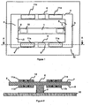
- a micromechanical device comprises a movable beam 1 attached by its two ends 2 to a rigid frame 3, preferably a flat frame.
- the beam 1 is, for example, made of silica (SiO2), silicon nitride (Si3N4) or monocrystalline or polycrystalline silicon.
- the frame 3 may, for example, also be made of silica (SiO 2), silicon nitride (Si 3 N 1) or monocrystalline or polycrystalline silicon, optionally accompanied by a metal or a plurality of metals or a nitride compound based on metal, for example TaN or TiN, or a piezoelectric material, for example AlN.
- the frame 3 is made of a low stress type silica layer (SiO2 low stress) obtained by a PECVD process which also forms the beam 1.
- the part of this layer which corresponds to the frame 3 can also include silicon nitride layers (deposited for example by high frequency plasma deposition).
- the frame 3 comprises two arms 4 each having two ends 5 respectively integral with the two ends 2 of the movable beam 1.
- Each arm 4 has a median portion 6 disposed between the two ends 5 of the corresponding arm 4
- the frame 3 must be rigid relative to the mobile beam 1, that is to say the ability of the frame 3 to deform following a stress applied by the beam 1 on the frame 3 is negligible.
- the thickness of the frame 3 is, for example, three times greater than the thickness of the beam 1 and the width of each arm 4 is, for example, ten times greater than its thickness.
- the width of the beam 1 can be comparable to that of the arms 4, so that the section of the arms 4 is about three times greater than that of the beam 1.
- the material of the arms 4 has, preferably , a Young's modulus higher than the Young's modulus of the material of the beam 1.
- the beam 1 is typically 500 microns long and 50 microns wide and the arms are 100 microns wide.
- the arms 4 of the frame 3 and the middle part 6 have a front face 7 and a rear face 8.
- the middle part 6 of each arm 4 can be arranged with said rear face 8 on a base 9 secured to a support 10 of base, so that the frame 3 and the beam 1 are away from the base support 10.
- the base support 10 is, for example, plane.
- the frame 3 comprises at least one pair of elements 11 under stress 11a and rear 11b arranged, one facing each other, respectively to the front face 7 and at the back 8 of the arms 4.
- the frame 3 comprises four pairs of elements 11 under stress, in particular two pairs for each arm 4 disposed respectively on either side of the median part 6 of the corresponding arm 4.
- the figure 2 are represented two pairs of elements 11 front (11a) and rear (11b) arranged on the arms, respectively on either side of the middle portion 6 and, thus, the base 9.
- a first pair of front elements (11a) and rear (11b) is arranged on the left on the figure 2
- a second pair of front (11a) and rear (11b) elements is disposed to the right on the figure 2 .
- the elements 11 make it possible to control the state of stress of the mobile beam 1 and, thus, to adjust the compressive or tensile stress of the beam 1. This notably makes it possible to control the deformation of the beam 1.
- the elements 11 under stress may consist of thin layers under tensile stress or thin layers under compressive stress. Each element 11 may also consist of a stack of thin layers.
- the elements 11 represented in figure 2 are thin films under tensile stress, as represented by arrows 12.
- the beam 1 is preferably under high compression, which makes it possible to obtain two states of very stable equilibriums. It should be noted that the beam then has a longitudinal stress. The stress is adjusted before the main beam movement, that is, the beam does not move when the stress is adjusted.
- Two stable positions can be obtained by flaring the beam 1, which requires that the force due to the compressive stresses of the beam 1 is greater than the first critical load of Euler.
- the compressive stresses are due, on the one hand, to the stresses specific to the beam 1, that is to say the residual stresses due to the deposition process, and, on the other hand, to the tensile stresses of the elements 11. of the frame 3, causing the increase in the compressive stress of the beam 1.
- the front face 7 and the rear face 8 When the elements 11 are arranged on the two faces of the arms 4, the front face 7 and the rear face 8, a bimetallic effect, exerting a force transverse to the arms 4, is avoided.
- the stresses thus create essentially longitudinal forces in the arms 4.
- the thicknesses of the elements 11a and 11b must be adapted, in order to avoid any bimetallic effect.
- a first value can be calculated by using the Hooke's law, known from the mechanics of continuous media, a law which links the residual stress to the deformation. Then the skilled person can proceed by successive trials.
- a forward force exerted on one of the arms 4 by the element 11a before a pair of elements is preferably substantially equal to a rear force exerted on the same arm 4 by the rear element 11b corresponding.
- another possible solution is to include patterns in the frame where the beam is embedded which will stiffen the elements 11, for example lines in the longitudinal direction of the arms 4 .
- the elements 11 under stress may comprise first actuators.
- each element 11 is constituted by a first actuator, as shown in FIG. figure 3 .
- the first actuators are respectively disposed at the front face 7 and the rear face 8 of the arms 4.
- the front and rear elements 11 are active, whereas in the embodiment described above, the elements 1 before and back are passive.
- the first actuators constituting the elements 11 are particularly interesting in the case of bistable switches.
- the bistable switches optionally comprise, in addition, second actuators 15 for actuating the beam 1, shown in FIG. figure 1 .
- the actuation of the beam 1 by means of the second actuators 15 makes it possible, for example in the case of a microswitch, to establish an electrical contact between conductive elements disposed respectively at a lower face of the beam 1 and on the support 10.
- a bistable switch according to the invention makes it possible to obtain a high contact force and a high stability of the equilibrium positions while making switching possible. The switch is then more resistant to the influences of the external environment, for example shocks or fields of external forces or potential.
- the first actuators of the elements 11 make it possible to modify the stresses in the frame 3 and, thus, to reduce the internal compressive and tensile stresses of the beam 1. This facilitates the passage of the switch from a first position to a second position.
- the first actuators are preferably chosen from thermal actuators, piezoelectric actuators and electrostatic, electrostrictive, electromagnetic and magnetostrictive actuators.
- the first actuators are, for example, actuators consisting of thin layers.
- the layers constituting the first actuators are, for example, aluminum nitride, a compound comprising zirconium, titanium, lead and oxygen such as Pb (Zr, Ti) O 3 or a compound containing magnesium, zirconium, niobium, lead and oxygen such as xPb (Mg 1/3 Nb 2/3 ) O 3 (1-x ) PbTi0 3 .
- electrical power supplies 13 make it possible to apply an electric voltage to the ends of each of the thin layers constituting the first actuators, so as to obtain a stress, for example in compression, illustrated by arrows 14.
- the stress can also be a constraint traction.
- the thermal actuators are, for example, constituted by metal layers. When the metal layers are traversed by an electric current, their volume increases, which makes it possible to exert a tensile force on the frame 3.
- a metal having a high coefficient of thermal expansion, a low heat capacity is preferably chosen. , good temperature resistance and a high Young's modulus.
- this thin layer will be given, during the lithography step, a particular shape capable of increasing the longitudinal deformation of the beam 1.
- the beam 1 may, for example, comprise four second actuators 15, in particular two second actuators 15 disposed on the lower face of the beam 1 and two second actuators 15 arranged on the upper face of the beam 1, which makes it possible to realize the actuation of the beam 1 using only the second actuators 15.
- the beam 1 comprises only two second actuators 15, which makes it possible to favor a stability position of the beam 1, for example a top position when two tensile stress elements are placed on the upper face of the beam 1 or a bottom position when two elements under compressive stress are placed on the upper face of the beam. Beam 1.
- the second actuators 15 and the first actuators must be used to move to a position of lesser stability, whereas, to move into the highest stability position, it is sufficient to actuate the first actuators. only.
- the device according to the invention may have any geometry.
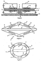
- frame 3 may have the geometry of a rhombus or a circle.
- the elements 11 may, for example, cover all of the arms 4 of the frame 3.
- the resonance frequency and the initial capacitance value can be adjusted respectively.
- the trip threshold can be adjusted.
- the actuating voltage can be adjusted and in particular decreased, which reduces the electrical operating voltage. All these adjustments can be made before or during the operation of the devices.
- a compression-stressed layer may, for example, be produced by depositing a layer of silica or silicon nitride deposited by low frequency plasma.
- a tensile stress layer can be made by depositing a silicon nitride (for example by high frequency plasma deposition), a tantalum nitride (TaN) or a titanium (TiN) or a metal, by Examples are tantalum, platinum, gold, silver, aluminum, manganese, zinc and nickel or a nickel-based alloy (eg FeNiCr inconel). Metals have the advantage of having a high coefficient of thermal expansion, which implies a good expansion potential.
- the second actuators 15 of a microswitch comprise actuating electrodes each comprising transversely to the beam 1, a central zone 16 disposed on the beam 1 and two flanges 17 laterally projecting flexible.
- Each lateral wing 17 is attached to the corresponding central zone 16 by a narrower connecting zone 18, disposed on one side of the wing 17 closest to the center C of the beam 1.
- the free ends 19 of the lateral wings 17 bend towards the support 10 and, thus, the electrostatic attractive force at the free ends 19 increases .
- the free ends 19 bend further and drive the beam 1 towards the support 10, the corresponding force between the wings 17 and the beam 1 being transmitted via the connecting zones 18.
- the addition of the wings 17 side allows more to decrease the electrical tension of actuation of the switch.
- the median part 6 of each arm 4 has a lateral extension 20.
- the lateral extensions 20 are, for example, arranged in the plane of the frame 3 and the bases 9 are arranged under the lateral extensions 20 of the arms 4.
- the parts 6 medians are connected to the bases via the lateral extensions 20. It is also possible to consider attaching the lateral extension 20 directly to the base support 10, so that the beam 1 and at least the ends 5 of the arms 4
- the lateral extensions 20 may, for example, themselves form a base.
- the support 10 may comprise a cavity disposed facing the mobile beam 1.
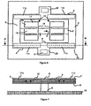
- the two elements 11c under stress are integrated in the frame 3, respectively two in each arm 4.
- the two elements 11c of an arm 4 are respectively disposed on either side of the median part 6 of the arm 4, between the part median 6 and the corresponding end 5.
- the two elements 11c are centered between the front face 7 and the rear face 8 of the corresponding arm 4, in such a way that the stresses essentially create longitudinal forces in the arms 4, which makes it possible to avoid any bimetallic effect. It is then important to arrange the elements 11c symmetrically with respect to the neutral fiber of the arms 4, that is to say relative to the middle of the suspended assembly.
- the elements 11c are preferably active elements, for example thermal elements, expanding during the passage of an electric current.
- the elements 11c may have a shape comprising meanders.
- one or more additional layers may be arranged between the elements 11c, on the one hand, and the material respectively constituting the front 7 and rear 8 faces of the arms 4, on the other hand.
- the second actuators 15 may also be arranged to be centered between the corresponding front and rear faces, that is to say the front and rear faces of the beam 1.
- the beam 1 may also be reinforced via one or more additional layers exposed between the second actuators 15, on the one hand, and the material respectively constituting the front and rear faces of the beam 1, on the other hand.
- the second actuators 15 are, for example, thermal active elements, preferably made simultaneously with the elements 11.
- the mechanical characteristics Young's modulus and Poisson's ratio
- the residual stresses of the thin layers which one wishes to use are firstly determined. This can be done experimentally or theoretically Materials and thicknesses are chosen so as to ensure that the frame is very rigid with respect to the beam, that is to say so that the residual stresses of the deposition of the material of the beam does not deform the frame.
- the geometrical parameters of the beam which best correspond to the intended application can be determined by means of a theoretical model, for example the mechanical model proposed in the article "We have a tunable BISTABLE MEMS-Theory and Experiment" by MTA Saif (J.
- the invention is not limited to the embodiments shown. In particular, it is possible to envisage a combination of the first passive or active actuators with second active or passive actuators.
Landscapes
- Engineering & Computer Science (AREA)
- Mechanical Engineering (AREA)
- Manufacturing & Machinery (AREA)
- Microelectronics & Electronic Packaging (AREA)
- Micromachines (AREA)
Claims (14)
- Mikromechanische Vorrichtung, die einen beweglichen Balken (1) umfasst, der an seinen beiden Enden (2) mit einem Rahmen (3) verbunden ist, sowie Mittel zur Kontrolle der Durchbiegung des Balkens, wobei sich der Balken (1) in einem Zustand vorbestimmter Spannung befindet, Vorrichtung, die dadurch gekennzeichnet ist, dass der Rahmen (3) steifer ist als der Balken und zwei Arme (4) umfasst, die jeweils zwei Enden (5) haben, die jeweils fest mit den beiden Enden (2) des beweglichen Balkens (1) verbunden sind und jeweils einen Mittelteil (6) aufweisen, der zwischen den beiden Enden (5) des entsprechenden Arms (4) angeordnet ist, wobei die Arme (4) und ihre Mittelteile (6) eine Vorderseite (7) und eine Rückseite (8) aufweisen, wobei die Rückseite (8) des Mittelteils (8) jedes Arms (4) mit einem Basisträger (10) verbunden ist und die Mittel zur Kontrolle der Durchbiegung des Balkens mindestens ein unter Spannung stehendes Element (11) umfassen, das zum Rahmen (3) gehört und die Anpassung des vorgenannten Spannungszustands des Balkens erlaubt.
- Vorrichtung nach Anspruch 1, dadurch gekennzeichnet, dass das unter Spannung stehende Element (11) von einer dünnen, unter Zugspannung stehenden Schicht gebildet wird.
- Vorrichtung nach Anspruch 1, dadurch gekennzeichnet, dass das unter Spannung stehende Element (11) von einer dünnen, unter Druckspannung stehenden Schicht gebildet wird.
- Vorrichtung nach einem der Ansprüche 1 bis 3, dadurch gekennzeichnet, dass das unter Spannung stehende Element (11) eine erste Betätigungseinrichtung umfasst.
- Vorrichtung nach Anspruch 4, dadurch gekennzeichnet, dass die erste Betätigungseinrichtung aus der Gruppe der thermischen, piezoelektrischen, elektrostatischen, elektrostriktiven, elektromagnetischen und magnetostriktiven Betätigungseinrichtungen ausgewählt ist.
- Vorrichtung nach einem der Ansprüche 4 und 5, dadurch gekennzeichnet, dass die erste Betätigungseinrichtung von mindestens einer dünnen Schicht gebildet wird.
- Vorrichtung nach Anspruch 6, dadurch gekennzeichnet, dass sie Mittel (13) zum Anlegen einer elektrischen Spannung zwischen zwei Enden der dünnen Schicht umfasst, die die erste Betätigungseinrichtung bildet.
- Vorrichtung nach einem der Ansprüche 1 bis 7, dadurch gekennzeichnet, dass das unter Spannung stehende Element (11c) zwischen der Vorderseite (7) und der Rückseite (8) des entsprechenden Arms (4) zentriert ist.
- Vorrichtung nach einem der Ansprüche 1 bis 7, dadurch gekennzeichnet, dass der Rahmen (3) mindestens ein Paar unter Spannung stehender Elemente (11) umfasst, und zwar ein vorderes (11a) und ein hinteres (11b), die einander gegenüberliegend jeweils auf der Vorderseite (7) und der Rückseite (8) der Arme (4) angeordnet sind.
- Vorrichtung nach Anspruch 9, dadurch gekennzeichnet, dass, nachdem das unter Spannung stehende vordere Element (11a) und das unter Spannung stehende hintere Element (11b) eines Elementepaars jeweils eine vorderseitige und eine rückseitige Kraft auf die Vorder- und Rückseite des jeweiligen Arms (4) ausüben, die von den Elementen (11) eines Elementepaars (11) ausgeübten vorder- und rückseitigen Kräfte im Wesentlichen gleich sind.
- Vorrichtung nach einem der Ansprüche 9 und 10, dadurch gekennzeichnet, dass jeder Arm (4) zwei Paar unter Spannung stehender Elemente (11), nämlich ein vorderes (11a) und ein hinteres (11b), umfasst, die jeweils beidseits des Mittelteils (6) des jeweiligen Arms (4) angeordnet sind.
- Vorrichtung nach einem der Ansprüche 1 bis 11, dadurch gekennzeichnet, dass der Mittelteil (6) jedes Arms (4) eine seitliche Verlängerung (20) umfasst, die mit dem Basisträger (10) verbunden ist.
- Vorrichtung nach einem der Ansprüche 1 bis 12, dadurch gekennzeichnet, dass die Rückseite (8) des Mittelteils (8) jedes Arms (4) auf einem Sockel angeordnet ist, der fest mit dem Basisträger (10) verbunden ist.
- Vorrichtung nach einem der Ansprüche 1 bis 13, dadurch gekennzeichnet, dass leitende Elemente jeweils auf einer unteren Seite des Balkens und auf dem Basisträger angeordnet sind, um ein elektrisches Kontakt zwischen diesen Elementen zu ermöglichen, wobei die Vorrichtung ein Mikroschalter bildet.
Applications Claiming Priority (2)
| Application Number | Priority Date | Filing Date | Title |
|---|---|---|---|
| FR0501239A FR2881730B1 (fr) | 2005-02-08 | 2005-02-08 | Dispositif micromecanique comportant une poutre mobile |
| PCT/FR2006/000246 WO2006084977A1 (fr) | 2005-02-08 | 2006-02-02 | Dispositif micromecanique comportant une poutre mobile |
Publications (3)
| Publication Number | Publication Date |
|---|---|
| EP1846320A1 EP1846320A1 (de) | 2007-10-24 |
| EP1846320B1 true EP1846320B1 (de) | 2008-06-25 |
| EP1846320B8 EP1846320B8 (de) | 2009-04-08 |
Family
ID=34954641
Family Applications (1)
| Application Number | Title | Priority Date | Filing Date |
|---|---|---|---|
| EP06709238A Expired - Lifetime EP1846320B8 (de) | 2005-02-08 | 2006-02-02 | Mikromechanische vorrichtung mit einem beweglichen balken |
Country Status (6)
| Country | Link |
|---|---|
| US (1) | US7610814B2 (de) |
| EP (1) | EP1846320B8 (de) |
| JP (1) | JP2008529813A (de) |
| DE (1) | DE602006001577D1 (de) |
| FR (1) | FR2881730B1 (de) |
| WO (1) | WO2006084977A1 (de) |
Families Citing this family (3)
| Publication number | Priority date | Publication date | Assignee | Title |
|---|---|---|---|---|
| US8039312B1 (en) * | 2010-07-30 | 2011-10-18 | Freescale Semiconductor, Inc. | Method for forming a capped micro-electro-mechanical system (MEMS) device |
| DE102019116779B3 (de) * | 2019-06-21 | 2020-07-30 | Christian-Albrechts-Universität Zu Kiel | Messvorrichtung für schwache, langsam veränderliche Magnetfelder, insbesondere für biomagnetische Felder |
| FR3103966B1 (fr) * | 2019-11-28 | 2021-12-03 | Commissariat Energie Atomique | Microsystème mécanique et procédé de fabrication associé |
Family Cites Families (15)
| Publication number | Priority date | Publication date | Assignee | Title |
|---|---|---|---|---|
| EP0262253A1 (de) * | 1986-10-03 | 1988-04-06 | International Business Machines Corporation | Mikromechanische Fühlervorrichtung für atomare Kräfte |
| JPH091795A (ja) * | 1995-06-15 | 1997-01-07 | Sharp Corp | インクジェットヘッド |
| US6073484A (en) * | 1995-07-20 | 2000-06-13 | Cornell Research Foundation, Inc. | Microfabricated torsional cantilevers for sensitive force detection |
| US6295272B1 (en) * | 1998-04-20 | 2001-09-25 | Gadzoox Networks, Inc. | Subchannel modulation scheme for carrying management and control data outside the regular data channel |
| AUPP993199A0 (en) * | 1999-04-22 | 1999-05-20 | Silverbrook Research Pty Ltd | A micromechanical device and method (ij46p2a) |
| US6218762B1 (en) * | 1999-05-03 | 2001-04-17 | Mcnc | Multi-dimensional scalable displacement enabled microelectromechanical actuator structures and arrays |
| US6463499B1 (en) * | 1999-10-14 | 2002-10-08 | Hewlett-Packard Company | Data bus cable having SCSI and IIC bus functionality and process for using the same |
| JP2001305472A (ja) * | 2000-04-24 | 2001-10-31 | Olympus Optical Co Ltd | 光偏向器 |
| DE10061205B4 (de) * | 2000-12-08 | 2006-01-05 | Eads Deutschland Gmbh | Mikromechanischer Mikrowellenschalter |
| US20020136485A1 (en) * | 2001-02-02 | 2002-09-26 | Reed Jason D. | Apparatus and method for micro-electromechanical systems two-dimensional large movement electrostatic comb drive |
| US6784771B1 (en) * | 2001-07-24 | 2004-08-31 | New Peregrine, Inc. | MEMS optical mirror array |
| US6707176B1 (en) * | 2002-03-14 | 2004-03-16 | Memx, Inc. | Non-linear actuator suspension for microelectromechanical systems |
| JP2004074341A (ja) * | 2002-08-15 | 2004-03-11 | Murata Mfg Co Ltd | 半導体装置 |
| WO2004079292A2 (en) * | 2003-02-28 | 2004-09-16 | Southwest Research Institute | Mems sensor for detecting stress corrosion cracking |
| WO2005116621A2 (en) * | 2004-05-25 | 2005-12-08 | The Government Of The United States Of America, As Represented By The Secretary Of The Navy Naval Research Laboratory | Microelectro-mechanical chemical sensor |
-
2005
- 2005-02-08 FR FR0501239A patent/FR2881730B1/fr not_active Expired - Fee Related
-
2006
- 2006-02-02 DE DE602006001577T patent/DE602006001577D1/de not_active Expired - Lifetime
- 2006-02-02 EP EP06709238A patent/EP1846320B8/de not_active Expired - Lifetime
- 2006-02-02 US US11/794,807 patent/US7610814B2/en not_active Expired - Fee Related
- 2006-02-02 WO PCT/FR2006/000246 patent/WO2006084977A1/fr not_active Ceased
- 2006-02-02 JP JP2007554593A patent/JP2008529813A/ja active Pending
Also Published As
| Publication number | Publication date |
|---|---|
| WO2006084977A1 (fr) | 2006-08-17 |
| EP1846320A1 (de) | 2007-10-24 |
| US20080148864A1 (en) | 2008-06-26 |
| EP1846320B8 (de) | 2009-04-08 |
| FR2881730B1 (fr) | 2007-06-01 |
| JP2008529813A (ja) | 2008-08-07 |
| FR2881730A1 (fr) | 2006-08-11 |
| DE602006001577D1 (de) | 2008-08-07 |
| US7610814B2 (en) | 2009-11-03 |
Similar Documents
| Publication | Publication Date | Title |
|---|---|---|
| EP2663091B1 (de) | Digitaler Lautsprecher mit verbesserter Leistung | |
| EP2309559A1 (de) | Piezoelektrische Erregerstruktur mit integriertem piezoresistivem Dehnmessstreifen und Herstellungsverfahren dafür | |
| EP1562207B1 (de) | Mikroelektromechanisches System mit zwei stabilen Kipplagen | |
| EP1736435A1 (de) | Elektrostatischer Aktuator mit einem leitendem und hängendem Schwenkteil | |
| WO1999031689A1 (fr) | Microsysteme a element deformable sous l'effet d'un actionneur thermique | |
| WO2015091836A1 (fr) | Dispositif optique pour la stabilisation d'images | |
| EP3257808B1 (de) | Mikroelektromechanische und/oder nanoelektromechanische vorrichtung mit bewegung ausserhalb der ebene, die mit kapazitiven mitteln zur änderung der oberfläche ausgestattet ist | |
| EP2616386B1 (de) | In der ebene betätigte resonanzvorrichtung und verfahren zur herstellung der vorrichtung | |
| EP0983609A1 (de) | Verfahren zur herstellung eines mikrosensors mit mikrogefertigtem silizium | |
| EP2736161B1 (de) | Betätigungsvorrichtung mit durch Kriechbewegung ausgelöstem Antriebselement | |
| EP1846320B1 (de) | Mikromechanische vorrichtung mit einem beweglichen balken | |
| EP1390793A2 (de) | Kippbarer optischer mikrospiegel, matrixanordnung für solche mikrospiegel und zugehöriges herstellungsverfahren | |
| EP3633336B1 (de) | Pyroelektrische detektionsvorrichtung mit starrer membran | |
| EP2949621A1 (de) | Kapazitive mikro- und/ oder nanoelektronische vorrichtung mit erhöhter kompaktheit | |
| WO2005015594A2 (fr) | Commutateur micro-mecanique bistable, methode d’actionnement et procede de realisation correspondant | |
| EP3037381B1 (de) | Vorrichtung zur umwandlung einer bewegung aus der ebene in eine bewegung in der ebene bzw. umgekehrt | |
| EP3828943B1 (de) | Mechanisches microsystem mit entsprechendem herstellungsprozess | |
| EP3264480B1 (de) | Elektromechanisches stellglied | |
| FR2884960A1 (fr) | Micro-condensateur electromecanique a capacite variable et procede de fabrication d'un tel micro-condensateur | |
| EP1805100B1 (de) | Mikrosystem mit verformbarer brücke | |
| EP3671873B1 (de) | Elektromechanisches mikrosystem, das ein aktives element mit einer strukturierten kernschicht umfasst | |
| EP3670438B1 (de) | Gelenk ausserhalb der ebene für mikro- und nanoelektromechanische systeme mit reduzierter nichtlinearität | |
| EP3415464A1 (de) | Mikroelektromechanische vorrichtung mit mindestens einem beweglichen element mit seitlicher bewegungsführung | |
| Mathur et al. | A low-stress microactuator array with integrated thin-film resistors | |
| FR3143256A1 (fr) | Elément actif piézoélectrique pour système électromécanique |
Legal Events
| Date | Code | Title | Description |
|---|---|---|---|
| PUAI | Public reference made under article 153(3) epc to a published international application that has entered the european phase |
Free format text: ORIGINAL CODE: 0009012 |
|
| 17P | Request for examination filed |
Effective date: 20070723 |
|
| AK | Designated contracting states |
Kind code of ref document: A1 Designated state(s): DE FR GR IT |
|
| GRAP | Despatch of communication of intention to grant a patent |
Free format text: ORIGINAL CODE: EPIDOSNIGR1 |
|
| GRAS | Grant fee paid |
Free format text: ORIGINAL CODE: EPIDOSNIGR3 |
|
| DAX | Request for extension of the european patent (deleted) | ||
| RBV | Designated contracting states (corrected) |
Designated state(s): DE FR GR IT |
|
| GRAA | (expected) grant |
Free format text: ORIGINAL CODE: 0009210 |
|
| AK | Designated contracting states |
Kind code of ref document: B1 Designated state(s): DE FR GR IT |
|
| REF | Corresponds to: |
Ref document number: 602006001577 Country of ref document: DE Date of ref document: 20080807 Kind code of ref document: P |
|
| RBV | Designated contracting states (corrected) |
Designated state(s): DE FR GB IT |
|
| PLBE | No opposition filed within time limit |
Free format text: ORIGINAL CODE: 0009261 |
|
| STAA | Information on the status of an ep patent application or granted ep patent |
Free format text: STATUS: NO OPPOSITION FILED WITHIN TIME LIMIT |
|
| 26N | No opposition filed |
Effective date: 20090326 |
|
| PGFP | Annual fee paid to national office [announced via postgrant information from national office to epo] |
Ref country code: FR Payment date: 20120316 Year of fee payment: 7 |
|
| PGFP | Annual fee paid to national office [announced via postgrant information from national office to epo] |
Ref country code: IT Payment date: 20120220 Year of fee payment: 7 Ref country code: GB Payment date: 20120217 Year of fee payment: 7 |
|
| PGFP | Annual fee paid to national office [announced via postgrant information from national office to epo] |
Ref country code: DE Payment date: 20120320 Year of fee payment: 7 |
|
| GBPC | Gb: european patent ceased through non-payment of renewal fee |
Effective date: 20130202 |
|
| REG | Reference to a national code |
Ref country code: FR Ref legal event code: ST Effective date: 20131031 |
|
| REG | Reference to a national code |
Ref country code: DE Ref legal event code: R119 Ref document number: 602006001577 Country of ref document: DE Effective date: 20130903 |
|
| PG25 | Lapsed in a contracting state [announced via postgrant information from national office to epo] |
Ref country code: IT Free format text: LAPSE BECAUSE OF NON-PAYMENT OF DUE FEES Effective date: 20130202 |
|
| PG25 | Lapsed in a contracting state [announced via postgrant information from national office to epo] |
Ref country code: DE Free format text: LAPSE BECAUSE OF NON-PAYMENT OF DUE FEES Effective date: 20130903 Ref country code: GB Free format text: LAPSE BECAUSE OF NON-PAYMENT OF DUE FEES Effective date: 20130202 Ref country code: FR Free format text: LAPSE BECAUSE OF NON-PAYMENT OF DUE FEES Effective date: 20130228 |