EP1847496A2 - Automatischer Wickler - Google Patents
Automatischer Wickler Download PDFInfo
- Publication number
- EP1847496A2 EP1847496A2 EP07105989A EP07105989A EP1847496A2 EP 1847496 A2 EP1847496 A2 EP 1847496A2 EP 07105989 A EP07105989 A EP 07105989A EP 07105989 A EP07105989 A EP 07105989A EP 1847496 A2 EP1847496 A2 EP 1847496A2
- Authority
- EP
- European Patent Office
- Prior art keywords
- yarn
- supply bobbin
- package
- bobbin
- automatic winder
- Prior art date
- Legal status (The legal status is an assumption and is not a legal conclusion. Google has not performed a legal analysis and makes no representation as to the accuracy of the status listed.)
- Withdrawn
Links
- 238000004804 winding Methods 0.000 claims description 38
- 238000001514 detection method Methods 0.000 claims description 14
- 238000010521 absorption reaction Methods 0.000 claims 1
- 238000005259 measurement Methods 0.000 description 2
- 230000001186 cumulative effect Effects 0.000 description 1
- 230000007423 decrease Effects 0.000 description 1
- 238000010586 diagram Methods 0.000 description 1
- 238000000034 method Methods 0.000 description 1
- 238000009987 spinning Methods 0.000 description 1
Images


Classifications
-
- B—PERFORMING OPERATIONS; TRANSPORTING
- B65—CONVEYING; PACKING; STORING; HANDLING THIN OR FILAMENTARY MATERIAL
- B65H—HANDLING THIN OR FILAMENTARY MATERIAL, e.g. SHEETS, WEBS, CABLES
- B65H49/00—Unwinding or paying-out filamentary material; Supporting, storing or transporting packages from which filamentary material is to be withdrawn or paid-out
- B65H49/18—Methods or apparatus in which packages rotate
- B65H49/34—Arrangements for effecting positive rotation of packages
-
- B—PERFORMING OPERATIONS; TRANSPORTING
- B65—CONVEYING; PACKING; STORING; HANDLING THIN OR FILAMENTARY MATERIAL
- B65H—HANDLING THIN OR FILAMENTARY MATERIAL, e.g. SHEETS, WEBS, CABLES
- B65H59/00—Adjusting or controlling tension in filamentary material, e.g. for preventing snarling; Applications of tension indicators
- B65H59/38—Adjusting or controlling tension in filamentary material, e.g. for preventing snarling; Applications of tension indicators by regulating speed of driving mechanism of unwinding, paying-out, forwarding, winding, or depositing devices, e.g. automatically in response to variations in tension
- B65H59/384—Adjusting or controlling tension in filamentary material, e.g. for preventing snarling; Applications of tension indicators by regulating speed of driving mechanism of unwinding, paying-out, forwarding, winding, or depositing devices, e.g. automatically in response to variations in tension using electronic means
- B65H59/387—Regulating unwinding speed
-
- B—PERFORMING OPERATIONS; TRANSPORTING
- B65—CONVEYING; PACKING; STORING; HANDLING THIN OR FILAMENTARY MATERIAL
- B65H—HANDLING THIN OR FILAMENTARY MATERIAL, e.g. SHEETS, WEBS, CABLES
- B65H63/00—Warning or safety devices, e.g. automatic fault detectors, stop-motions ; Quality control of the package
- B65H63/08—Warning or safety devices, e.g. automatic fault detectors, stop-motions ; Quality control of the package responsive to delivery of a measured length of material, completion of winding of a package, or filling of a receptacle
-
- B—PERFORMING OPERATIONS; TRANSPORTING
- B65—CONVEYING; PACKING; STORING; HANDLING THIN OR FILAMENTARY MATERIAL
- B65H—HANDLING THIN OR FILAMENTARY MATERIAL, e.g. SHEETS, WEBS, CABLES
- B65H2701/00—Handled material; Storage means
- B65H2701/30—Handled filamentary material
- B65H2701/31—Textiles threads or artificial strands of filaments
Definitions
- the present invention relates to an automatic winder for unwinding yarns from yarn supply bobbins to rewind the yarns onto packages.
- Automatic winders unwind a number of spun yarns from yarn supply bobbins produced by a ring spinner or the like, and splice the unwound yarns before rewinding them onto packages. Since package productivity largely depends on winding speed, there is a need for automatic winders that can achieve high-speed winding. High-speed winding, however, involves unwinding yarns from yarn supply bobbins at high speed, and the high-speed unwinding causes yarn unwinding tension to vary significantly. The variation in the unwinding tension results in, for example, sloughing of yarns (i.e., the yarns being entangled and unwound together at a stretch as in slipping off) or fluffing caused by contact of unwound yarns.
- automatic winders with an unwinding assist device have been proposed, as disclosed in Japanese Patent Nos. 3033370 and 2936917 , for example.
- the automatic winders control tension of balloons around yarn supply bobbins and tension of traveling yarns, thereby reducing sloughing and fluffing.
- unwinding spinning bobbins in particular, for fine count yarns
- even such automatic winders have limitations on their capability and cannot prevent, for example, occurrence of yarn breaks due to sloughing, or occurrence of fluffing, as the amount of yarn on the yarn supply bobbins decreases.
- a problem sought to be solved by the present invention is to provide an automatic winder capable of suppressing sloughing, fluffing, etc., even when used with yarn supply bobbins for various counts and types of yarn, including fine count yarns.
- An automatic winder unwinds a yarn from a yarn supply bobbin to rewind the yarn onto a package, and comprises rotational drive means for rotationally driving the yarn supply bobbin about its central axis in a yarn unwinding direction, thereby positively unwinding the yarn.
- the automatic winder further comprises a drum that is brought into contact with the package to rotationally drive the package, and the rotational drive means rotates the yarn supply bobbin at a speed higher than a rotational speed of the drum.
- the automatic winder further comprises control means for controlling the rotational drive means, and detection means for detecting an amount of yarn remaining on the supply bobbin, and the control means changes the rotational speed of the yarn supply bobbin in accordance with the amount of yarn remaining on the yarn supply bobbin detected by the detection means.
- the automatic winder includes the means for rotationally driving the yarn supply bobbin about its central axis at high-speed in the direction opposite to the yarn winding direction.
- the rotational drive means makes it possible to positively unwind the yarn from the yarn supply bobbin, thereby significantly reducing tension variation of the yarn during high-speed unwinding, and therefore even when a yarn supply bobbin for a fine count yarn is used, it is possible to substantially eliminate occurrence of yarn breaks due to sloughing and occurrence of fluffing.
- FIG. 1 is a front view illustrating the automatic winder according to the present invention.
- the automatic winder includes a number of winding units 1 provided in parallel, and control devices 10 for controlling the winding units 1.
- the winding units 1 each include a yarn supply bobbin 3 produced by a ring spinner or the like, and a package 4 formed by rewinding a spun yarn Y from the yarn supply bobbin 3.
- the package 4 is in surface contact with a traverse drum 5 under an appropriate contact pressure.
- the traverse drum 5 is rotationally driven by, for example, a motor (not shown), so that the package 4 is rotated following the rotational drive of the traverse drum 5.
- the rotational speed of the traverse drum 5 is controlled by the control device 10.
- the traverse drum 5 is formed therein a spiral groove 53a for guiding and traversing the yarn Y from the yarn supply bobbin 3.
- the winding unit 1 rotationally drives the traverse drum 5 to traverse and unwind the yarn Y from the yarn supply bobbin 3, so that the unwound yarn Y is rewound onto the package 4.
- the yarn Y passes through a yarn guide 20, which stabilizes an unwound balloon, and a tension device 21, which controls winding tension.
- the winding unit 1 further includes yarn splicing means 30 between the yarn supply bobbin 3 and the package 4.
- the yarn splicing means 30 includes a yarn splicing device 31 such as a splicer; a suction mouth 32 for guiding an upper yarn on the package 4 side to the yarn splicing device 31; and a suction pipe 33 for guiding a lower yarn on the yarn supply bobbin 3 side to the yarn splicing device 31.
- the winding unit 1 further includes a clearer 35 for detecting and cutting a yarn fault, such as a slub, in the traveling yarn Y.
- the yarn splicing means 30 and the clearer 35 are connected to the control device 10, and after the clearer 35 detects and cuts the yarn fault, the yarn splicing means 30 splices the upper and lower yarns together and restarts winding.
- the winding unit 1 further includes rotational drive means 2 for rotationally driving the yarn supply bobbin 3 about its central axis C at high speed.
- the rotational drive means 2 in the present embodiment directly rotates and drives the yarn supply bobbin 3 attached to a drive shaft 2b of a motor 2a.
- the yarn supply bobbin 3 may be indirectly driven through belts, for example.
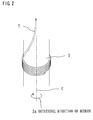
- the rotational drive means 2 rotationally drives the yarn supply bobbin 3 in a yarn unwinding direction. Specifically, as shown in FIG. 2, the rotational drive means 2 rotationally drives the yarn supply bobbin 3 in the yarn unwinding direction opposite to the winding direction 3a of the yarn Y around the yarn supply bobbin 3 (in the example of FIG.
- the yarn Y is wound clockwise, and therefore the bobbin 3 is rotated in the direction of an arrow; if the yarn Y is wound counterclockwise, the bobbin 3 is rotated in the direction opposite to the arrow), thereby positively unwinding the yarn Y from the yarn supply bobbin 3.
- the rotational drive means 2 is provided for each winding unit, and connected to the control device 10 provided in the winding unit, so that the rotational speed of the yarn supply bobbin 3 is controlled by the control device 10, independently of the other winding units.
- the rotational speed of the yarn supply bobbin 3 is controlled so as to be higher than the rotational speed of the traverse drum 5.
- the rotational speeds of the drum 5 and the bobbin 3 are controlled in such a manner that the amount of yarn unwound per unit of time is greater than the amount of yarn wound onto the package per unit of time (i.e., the yarn is slightly overfed).
- tension variation of the yarn Y from the yarn supply bobbin 3 during high-speed unwinding is reduced, resulting in a significant reduction in occurrence of tension-related breaks, sloughing-related breaks, fluffing, etc.
- the winding unit 1 includes detection means 6 for detecting the amount of yarn remaining on the yarn supply bobbin 3.
- the detection means 6 is composed of a distance sensor.
- the distance sensor 6 is connected to the control device 10.
- the distance sensor 6 is provided at a predetermined position from the bottom of the yarn supply bobbin 3 (at a height of about one-third of the length of the bobbin from the bottom). The unwinding tension of the yarn Y varies in accordance with the amount of yarn remaining on the yarn supply bobbin 3.
- the unwinding tension is sharply increased, resulting in significantly frequent occurrence of yarn breaks and sloughing.
- the distance sensor 6 constantly detects the distance to the yarn supply bobbin 3 from the predetermined position.
- the distance sensor 6 detects a change in the distance, thereby determining that the amount of yarn remaining on the yarn supply bobbin 3 is one-third of the original amount.
- the control device 10 controls the rotational drive means 2 so as to remain inactive from the beginning of winding until the amount of yarn is reduced to the vicinity of one-third of the original amount, and upon detection by the distance sensor 6, the control device 10 drives the rotational drive means 2 to rotate the yarn supply bobbin 3 at high speed, thereby preventing sloughing, etc.
- the detection means 6 may be a weight sensor for detecting the weight of the yarn Y to determine the remaining amount of yarn.
- the rotational speed of the yarn supply bobbin 3 may be changed in accordance with the amount of yarn remaining on the yarn supply bobbin 3 to correct tension variation.
- the winding unit 1 includes a length measurement device for managing the length of yarn to be wound by counting rotation pulses of the drum 5, it is possible to use the length measurement device as means for detecting the remaining amount of yarn.
- the control device 10 drives the rotational drive means 2 to rotate the yarn supply bobbin 3 at high speed, thereby preventing sloughing, etc.
- An increase in the amount of yarn on the package 4 increases the possibility that slippage might occur between the package 4 and the drum 5 when the drum 5 abruptly starts rotating at the time of starting the rotation of the package 4, so that the package 4 does not rotate in synchronization with the rotation of the yarn supply bobbin 3 with a lesser amount of yarn, resulting in over-unwinding on the yarn supply bobbin 3 side.
- Example 1 is directed to the case of rotating the yarn supply bobbin 3 from the beginning to end of unwinding of the yarn supply bobbin 3.
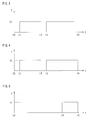
- FIG. 3 is a drive timing chart of the drum 5
- FIG. 4 is a drive timing chart of the bobbin rotation means 2.
- the winding unit 1 is supplied with a new bobbin 3 (a change of bobbins; t0)
- a yarn from the bobbing 3 is spliced to a yarn from the package 4 to restart winding (t1).
- the drum 5 is rotated at a winding speed V1
- the yarn supply bobbin rotation means 2 is also rotated at an unwinding speed v1.
- the traveling yarn is forcibly cut by a cutter (not shown) provided in the clearer 35 or a separately provided cutter (not shown) in accordance with a yarn fault detection signal.
- the clearer 35 turns off a yarn traveling signal (FW signal), so that the drive of the drum 5 is stopped (t2)- At this time, if the rotational drive means 2 for the yarn supply bobbin 3 keeps rotating, the yarn unwound from the bobbin 3 might twine around a nearby element, disturbing a yarn splicing operation.
- a suction pipe 40 as shown in FIG. 1 is preferably provided at a position facing a yarn guide. Also, it is necessary that the suction pipe 40 is configured to suction a certain length of the yarn and stop the suctioning operation in synchronization with stopping of the bobbin rotation.
- the winding is restarted (t3).
- the drum 5 stops operating and the bobbin rotation means 2 also stops driving (t5).
- the winding speed V1 is typically determined in accordance with the rotational speed of the drum 5, but even if the drum 5 is rotationally driven at a constant rotational speed, the traveling speed of the yarn being wound onto the package varies between the ends and the middle of the package during the traversing movement of the yarn, and the traveling speed of the yarn is constantly changed in accordance with, for example, depth variation of the traverse groove 5a formed in the drum 5 surface.
- Example 2 is directed to the case where the rotational drive means 2 remains inactive from the beginning of winding until the remaining amount of yarn reaches the vicinity of one-third of the original amount, and upon detection by the distance sensor 6, the rotational drive means 2 is driven to rotate the yarn supply bobbin 3 at high speed.
- the rotational drive means 2 remains inactive, and when the amount of yarn is reduced to approximately one-third of the original amount (t4), the rotational drive means 2 is driven to rotate the bobbin 3 in the unwinding direction.
- the amount of yarn remaining on the bobbin is detected by the sensor 6 (FIG. 1) or the like.
- Example 3 is directed to the case of controlling the rotational speed of the bobbin in relation to an increase in winding diameter of the package.
- An increase in the package diameter increases the possibility that the package 4, which is rotated by surface contact with the driven drum 5, might slip without following the rotation of the drum 5 at the time of restart of winding after yarn splicing, so that the yarn layer surface is damaged.
- the initial rotational speed of the package 4 may be controlled in accordance with the package diameter. In such a case, in order not to make the yarn slack, it is also necessary to change the rotational speed of the yarn supply bobbin 3 in relation to the package diameter.
- FIG. 6 is a package rotational speed chart
- FIG. 7 is a bobbin rotational speed chart corresponding to FIG. 6.
- the package 4 satisfactorily follows the drum 5 at the beginning of winding onto a new paper core (t10), resulting in a steep initial gradient.
- the rotation of the drum 5 is controlled such that the initial gradient (t12) after yarn splicing subsequent to yarn cutting (t11) is gentle compared to the gradient at the beginning of winding (t10), and when the package diameter is further increased, the initial gradient (t14) after restart of winding is further gentler.
- the bobbin rotational drive means 2 is controlled such that the initial rotational speed of the yarn supply bobbin (t10, t11, t14) is changed in accordance with the gradient of the package's initial rotational speed. By doing so, it becomes possible to avoid over-unwinding from the yarn supply bobbin 3, regardless of a change in the package diameter, thereby producing a satisfactory package without any yarn slack.
Landscapes
- Engineering & Computer Science (AREA)
- Quality & Reliability (AREA)
- Unwinding Of Filamentary Materials (AREA)
- Winding Filamentary Materials (AREA)
Applications Claiming Priority (1)
| Application Number | Priority Date | Filing Date | Title |
|---|---|---|---|
| JP2006113037A JP2007284196A (ja) | 2006-04-17 | 2006-04-17 | 自動ワインダー |
Publications (2)
| Publication Number | Publication Date |
|---|---|
| EP1847496A2 true EP1847496A2 (de) | 2007-10-24 |
| EP1847496A3 EP1847496A3 (de) | 2008-01-23 |
Family
ID=38226466
Family Applications (1)
| Application Number | Title | Priority Date | Filing Date |
|---|---|---|---|
| EP07105989A Withdrawn EP1847496A3 (de) | 2006-04-17 | 2007-04-11 | Automatischer Wickler |
Country Status (3)
| Country | Link |
|---|---|
| EP (1) | EP1847496A3 (de) |
| JP (1) | JP2007284196A (de) |
| CN (1) | CN101058377A (de) |
Cited By (3)
| Publication number | Priority date | Publication date | Assignee | Title |
|---|---|---|---|---|
| CN103010843A (zh) * | 2011-09-21 | 2013-04-03 | 村田机械株式会社 | 纱线卷绕机及纱线卷绕单元 |
| WO2017021576A3 (en) * | 2015-07-31 | 2017-03-30 | Sensing Tex, S.L. | Manufacturing method of luminous biaxial elastic knitted fabric, feed system of luminous fiber for coning on yarn-winding machines and biaxial elastic knitted fabric manufactured with said method |
| EP2593598B1 (de) * | 2010-06-01 | 2017-07-05 | Rotorcraft AG | Verfahren und vorrichtung zum ausreinigen von vorgarn |
Families Citing this family (6)
| Publication number | Priority date | Publication date | Assignee | Title |
|---|---|---|---|---|
| JP2014009405A (ja) * | 2012-06-27 | 2014-01-20 | Murata Mach Ltd | 紡績機 |
| DE102013004053A1 (de) * | 2013-03-08 | 2014-09-11 | Saurer Germany Gmbh & Co. Kg | Verfahren zum Betreiben einer Arbeitsstelle einer Kreuzspulen herstellenden Textilmaschine bzw. zugehörige Arbeitsstelle |
| CN103911702A (zh) * | 2014-01-28 | 2014-07-09 | 韵升控股集团有限公司 | 纱线断头监测装置 |
| CN107640664A (zh) * | 2017-10-17 | 2018-01-30 | 威海上进纺织机械有限公司 | 一种筒子纱称重剥离装置 |
| CN110194393A (zh) * | 2019-06-04 | 2019-09-03 | 东阳盛行自动化设备有限公司 | 一种线缆绕线装置 |
| IT202000019660A1 (it) * | 2020-08-07 | 2022-02-07 | Savio Macch Tessili Spa | Dispositivo e metodo per il controllo di un balloon, unità di roccatura comprendente tale dispositivo |
Family Cites Families (8)
| Publication number | Priority date | Publication date | Assignee | Title |
|---|---|---|---|---|
| DE212586C (de) * | ||||
| FR1525192A (fr) * | 1967-03-30 | 1968-05-17 | Dispositif de commande pour machine à teindre par enroulement et déroulement alternés, et machines similaires | |
| CH542781A (de) * | 1971-12-20 | 1973-10-15 | Schweiter Ag Maschf | Spulstelle einer Präzisionskreuzspulmaschine |
| US5188304A (en) * | 1987-02-27 | 1993-02-23 | Savio S.P.A. | Device and process for the handling and the control of the thread on a coner machine during the operation of spool change and of thread joining |
| JP2663293B2 (ja) * | 1989-03-02 | 1997-10-15 | 株式会社ロゼフテクノロジー | 偏平糸等のより戻し装置 |
| DE19640184B4 (de) * | 1996-09-30 | 2005-10-13 | Saurer Gmbh & Co. Kg | Verfahren zum Ausreinigen von Garnfehlern an einer Spulstelle einer Spulmaschine |
| DE19848881A1 (de) * | 1998-10-23 | 2000-04-27 | Schlafhorst & Co W | Verfahren zum Betreiben einer Arbeitsstelle einer Spulmaschine |
| DE10304366A1 (de) * | 2003-02-04 | 2004-08-05 | Saurer Gmbh & Co. Kg | Spulstelle für eine Kreuzspulen herstellende Textilmaschine |
-
2006
- 2006-04-17 JP JP2006113037A patent/JP2007284196A/ja active Pending
-
2007
- 2007-04-11 EP EP07105989A patent/EP1847496A3/de not_active Withdrawn
- 2007-04-17 CN CNA2007100970690A patent/CN101058377A/zh active Pending
Cited By (4)
| Publication number | Priority date | Publication date | Assignee | Title |
|---|---|---|---|---|
| EP2593598B1 (de) * | 2010-06-01 | 2017-07-05 | Rotorcraft AG | Verfahren und vorrichtung zum ausreinigen von vorgarn |
| CN103010843A (zh) * | 2011-09-21 | 2013-04-03 | 村田机械株式会社 | 纱线卷绕机及纱线卷绕单元 |
| CN103010843B (zh) * | 2011-09-21 | 2016-12-21 | 村田机械株式会社 | 纱线卷绕机及纱线卷绕单元 |
| WO2017021576A3 (en) * | 2015-07-31 | 2017-03-30 | Sensing Tex, S.L. | Manufacturing method of luminous biaxial elastic knitted fabric, feed system of luminous fiber for coning on yarn-winding machines and biaxial elastic knitted fabric manufactured with said method |
Also Published As
| Publication number | Publication date |
|---|---|
| CN101058377A (zh) | 2007-10-24 |
| JP2007284196A (ja) | 2007-11-01 |
| EP1847496A3 (de) | 2008-01-23 |
Similar Documents
| Publication | Publication Date | Title |
|---|---|---|
| EP1847496A2 (de) | Automatischer Wickler | |
| EP1857394B1 (de) | Verfahren zum Ausziehen des Garnendes aus einer Spule | |
| CN101759062A (zh) | 纱线卷绕装置及自动络纱机 | |
| EP2957664B1 (de) | Garnwickelvorrichtung und garnwickelsystem | |
| JP2016050053A (ja) | 糸巻取装置 | |
| CN102574655B (zh) | 纱线卷绕装置 | |
| JP2010089908A (ja) | 糸弛み取り装置及びこれを備える繊維機械 | |
| US6533211B2 (en) | Method of operating a textile machine for producing cheeses | |
| JP3951941B2 (ja) | 自動ワインダ | |
| CN103224167A (zh) | 纱线卷绕机及纱线卷绕方法 | |
| JP3651414B2 (ja) | 自動ワインダにおける毛羽抑制方法 | |
| JPH0470226B2 (de) | ||
| EP1795478A1 (de) | Textilmaschine | |
| JP2871278B2 (ja) | 自動ワインダの巻取ユニット | |
| EP4197949B1 (de) | Garnwickelmaschine | |
| JP2006188342A (ja) | 自動ワインダにおける弾性糸の巻取方法 | |
| JPH08225249A (ja) | 糸の巻取方法および糸の巻取装置 | |
| JP2936917B2 (ja) | 自動ワインダーのテンション制御装置 | |
| JP3430631B2 (ja) | 自動ワインダー | |
| JP2628582B2 (ja) | ドラム巻付防止方法 | |
| JP2936918B2 (ja) | 自動ワインダーのテンション制御装置 | |
| JPH06247629A (ja) | 自動ワインダのテンション制御装置 | |
| JP2007290839A (ja) | 巻き終わり糸の制御装置 | |
| JPH0735224B2 (ja) | 自動ワインダ−における巻取方法 | |
| JP2015196598A (ja) | 糸巻取装置、繊維機械、及び、パッケージの形成方法 |
Legal Events
| Date | Code | Title | Description |
|---|---|---|---|
| PUAI | Public reference made under article 153(3) epc to a published international application that has entered the european phase |
Free format text: ORIGINAL CODE: 0009012 |
|
| AK | Designated contracting states |
Kind code of ref document: A2 Designated state(s): AT BE BG CH CY CZ DE DK EE ES FI FR GB GR HU IE IS IT LI LT LU LV MC MT NL PL PT RO SE SI SK TR |
|
| AX | Request for extension of the european patent |
Extension state: AL BA HR MK YU |
|
| PUAL | Search report despatched |
Free format text: ORIGINAL CODE: 0009013 |
|
| AK | Designated contracting states |
Kind code of ref document: A3 Designated state(s): AT BE BG CH CY CZ DE DK EE ES FI FR GB GR HU IE IS IT LI LT LU LV MC MT NL PL PT RO SE SI SK TR |
|
| AX | Request for extension of the european patent |
Extension state: AL BA HR MK YU |
|
| AKX | Designation fees paid |
Designated state(s): DE IT |
|
| STAA | Information on the status of an ep patent application or granted ep patent |
Free format text: STATUS: THE APPLICATION IS DEEMED TO BE WITHDRAWN |
|
| 18D | Application deemed to be withdrawn |
Effective date: 20080724 |