EP1847713A2 - Pompe rotative réglable à usure réduite - Google Patents
Pompe rotative réglable à usure réduite Download PDFInfo
- Publication number
- EP1847713A2 EP1847713A2 EP07106407A EP07106407A EP1847713A2 EP 1847713 A2 EP1847713 A2 EP 1847713A2 EP 07106407 A EP07106407 A EP 07106407A EP 07106407 A EP07106407 A EP 07106407A EP 1847713 A2 EP1847713 A2 EP 1847713A2
- Authority
- EP
- European Patent Office
- Prior art keywords
- actuator
- sliding
- rotary pump
- pump according
- housing
- Prior art date
- Legal status (The legal status is an assumption and is not a legal conclusion. Google has not performed a legal analysis and makes no representation as to the accuracy of the status listed.)
- Granted
Links
Images
Classifications
-
- F—MECHANICAL ENGINEERING; LIGHTING; HEATING; WEAPONS; BLASTING
- F04—POSITIVE - DISPLACEMENT MACHINES FOR LIQUIDS; PUMPS FOR LIQUIDS OR ELASTIC FLUIDS
- F04C—ROTARY-PISTON, OR OSCILLATING-PISTON, POSITIVE-DISPLACEMENT MACHINES FOR LIQUIDS; ROTARY-PISTON, OR OSCILLATING-PISTON, POSITIVE-DISPLACEMENT PUMPS
- F04C14/00—Control of, monitoring of, or safety arrangements for, machines, pumps or pumping installations
- F04C14/18—Control of, monitoring of, or safety arrangements for, machines, pumps or pumping installations characterised by varying the volume of the working chamber
- F04C14/185—Control of, monitoring of, or safety arrangements for, machines, pumps or pumping installations characterised by varying the volume of the working chamber by varying the useful pumping length of the cooperating members in the axial direction
-
- F—MECHANICAL ENGINEERING; LIGHTING; HEATING; WEAPONS; BLASTING
- F04—POSITIVE - DISPLACEMENT MACHINES FOR LIQUIDS; PUMPS FOR LIQUIDS OR ELASTIC FLUIDS
- F04C—ROTARY-PISTON, OR OSCILLATING-PISTON, POSITIVE-DISPLACEMENT MACHINES FOR LIQUIDS; ROTARY-PISTON, OR OSCILLATING-PISTON, POSITIVE-DISPLACEMENT PUMPS
- F04C2/00—Rotary-piston machines or pumps
- F04C2/08—Rotary-piston machines or pumps of intermeshing-engagement type, i.e. with engagement of co-operating members similar to that of toothed gearing
- F04C2/12—Rotary-piston machines or pumps of intermeshing-engagement type, i.e. with engagement of co-operating members similar to that of toothed gearing of other than internal-axis type
- F04C2/14—Rotary-piston machines or pumps of intermeshing-engagement type, i.e. with engagement of co-operating members similar to that of toothed gearing of other than internal-axis type with toothed rotary pistons
- F04C2/18—Rotary-piston machines or pumps of intermeshing-engagement type, i.e. with engagement of co-operating members similar to that of toothed gearing of other than internal-axis type with toothed rotary pistons with similar tooth forms
-
- F—MECHANICAL ENGINEERING; LIGHTING; HEATING; WEAPONS; BLASTING
- F04—POSITIVE - DISPLACEMENT MACHINES FOR LIQUIDS; PUMPS FOR LIQUIDS OR ELASTIC FLUIDS
- F04C—ROTARY-PISTON, OR OSCILLATING-PISTON, POSITIVE-DISPLACEMENT MACHINES FOR LIQUIDS; ROTARY-PISTON, OR OSCILLATING-PISTON, POSITIVE-DISPLACEMENT PUMPS
- F04C2230/00—Manufacture
- F04C2230/90—Improving properties of machine parts
- F04C2230/91—Coating
-
- F—MECHANICAL ENGINEERING; LIGHTING; HEATING; WEAPONS; BLASTING
- F05—INDEXING SCHEMES RELATING TO ENGINES OR PUMPS IN VARIOUS SUBCLASSES OF CLASSES F01-F04
- F05C—INDEXING SCHEME RELATING TO MATERIALS, MATERIAL PROPERTIES OR MATERIAL CHARACTERISTICS FOR MACHINES, ENGINES OR PUMPS OTHER THAN NON-POSITIVE-DISPLACEMENT MACHINES OR ENGINES
- F05C2201/00—Metals
- F05C2201/90—Alloys not otherwise provided for
- F05C2201/903—Aluminium alloy, e.g. AlCuMgPb F34,37
-
- F—MECHANICAL ENGINEERING; LIGHTING; HEATING; WEAPONS; BLASTING
- F05—INDEXING SCHEMES RELATING TO ENGINES OR PUMPS IN VARIOUS SUBCLASSES OF CLASSES F01-F04
- F05C—INDEXING SCHEME RELATING TO MATERIALS, MATERIAL PROPERTIES OR MATERIAL CHARACTERISTICS FOR MACHINES, ENGINES OR PUMPS OTHER THAN NON-POSITIVE-DISPLACEMENT MACHINES OR ENGINES
- F05C2203/00—Non-metallic inorganic materials
- F05C2203/08—Ceramics; Oxides
- F05C2203/0865—Oxide ceramics
- F05C2203/0869—Aluminium oxide
-
- F—MECHANICAL ENGINEERING; LIGHTING; HEATING; WEAPONS; BLASTING
- F05—INDEXING SCHEMES RELATING TO ENGINES OR PUMPS IN VARIOUS SUBCLASSES OF CLASSES F01-F04
- F05C—INDEXING SCHEME RELATING TO MATERIALS, MATERIAL PROPERTIES OR MATERIAL CHARACTERISTICS FOR MACHINES, ENGINES OR PUMPS OTHER THAN NON-POSITIVE-DISPLACEMENT MACHINES OR ENGINES
- F05C2225/00—Synthetic polymers, e.g. plastics; Rubber
-
- F—MECHANICAL ENGINEERING; LIGHTING; HEATING; WEAPONS; BLASTING
- F05—INDEXING SCHEMES RELATING TO ENGINES OR PUMPS IN VARIOUS SUBCLASSES OF CLASSES F01-F04
- F05C—INDEXING SCHEME RELATING TO MATERIALS, MATERIAL PROPERTIES OR MATERIAL CHARACTERISTICS FOR MACHINES, ENGINES OR PUMPS OTHER THAN NON-POSITIVE-DISPLACEMENT MACHINES OR ENGINES
- F05C2225/00—Synthetic polymers, e.g. plastics; Rubber
- F05C2225/04—PTFE [PolyTetraFluorEthylene]
-
- F—MECHANICAL ENGINEERING; LIGHTING; HEATING; WEAPONS; BLASTING
- F05—INDEXING SCHEMES RELATING TO ENGINES OR PUMPS IN VARIOUS SUBCLASSES OF CLASSES F01-F04
- F05C—INDEXING SCHEME RELATING TO MATERIALS, MATERIAL PROPERTIES OR MATERIAL CHARACTERISTICS FOR MACHINES, ENGINES OR PUMPS OTHER THAN NON-POSITIVE-DISPLACEMENT MACHINES OR ENGINES
- F05C2225/00—Synthetic polymers, e.g. plastics; Rubber
- F05C2225/06—Polyamides, e.g. NYLON
-
- F—MECHANICAL ENGINEERING; LIGHTING; HEATING; WEAPONS; BLASTING
- F05—INDEXING SCHEMES RELATING TO ENGINES OR PUMPS IN VARIOUS SUBCLASSES OF CLASSES F01-F04
- F05C—INDEXING SCHEME RELATING TO MATERIALS, MATERIAL PROPERTIES OR MATERIAL CHARACTERISTICS FOR MACHINES, ENGINES OR PUMPS OTHER THAN NON-POSITIVE-DISPLACEMENT MACHINES OR ENGINES
- F05C2225/00—Synthetic polymers, e.g. plastics; Rubber
- F05C2225/12—Polyetheretherketones, e.g. PEEK
-
- F—MECHANICAL ENGINEERING; LIGHTING; HEATING; WEAPONS; BLASTING
- F05—INDEXING SCHEMES RELATING TO ENGINES OR PUMPS IN VARIOUS SUBCLASSES OF CLASSES F01-F04
- F05C—INDEXING SCHEME RELATING TO MATERIALS, MATERIAL PROPERTIES OR MATERIAL CHARACTERISTICS FOR MACHINES, ENGINES OR PUMPS OTHER THAN NON-POSITIVE-DISPLACEMENT MACHINES OR ENGINES
- F05C2251/00—Material properties
- F05C2251/10—Hardness
-
- F—MECHANICAL ENGINEERING; LIGHTING; HEATING; WEAPONS; BLASTING
- F05—INDEXING SCHEMES RELATING TO ENGINES OR PUMPS IN VARIOUS SUBCLASSES OF CLASSES F01-F04
- F05C—INDEXING SCHEME RELATING TO MATERIALS, MATERIAL PROPERTIES OR MATERIAL CHARACTERISTICS FOR MACHINES, ENGINES OR PUMPS OTHER THAN NON-POSITIVE-DISPLACEMENT MACHINES OR ENGINES
- F05C2251/00—Material properties
- F05C2251/14—Self lubricating materials; Solid lubricants
-
- Y—GENERAL TAGGING OF NEW TECHNOLOGICAL DEVELOPMENTS; GENERAL TAGGING OF CROSS-SECTIONAL TECHNOLOGIES SPANNING OVER SEVERAL SECTIONS OF THE IPC; TECHNICAL SUBJECTS COVERED BY FORMER USPC CROSS-REFERENCE ART COLLECTIONS [XRACs] AND DIGESTS
- Y10—TECHNICAL SUBJECTS COVERED BY FORMER USPC
- Y10T—TECHNICAL SUBJECTS COVERED BY FORMER US CLASSIFICATION
- Y10T29/00—Metal working
- Y10T29/49—Method of mechanical manufacture
- Y10T29/49229—Prime mover or fluid pump making
- Y10T29/49236—Fluid pump or compressor making
- Y10T29/49242—Screw or gear type, e.g., Moineau type
Definitions
- the invention relates to a rotary pump with adjustable, preferably adjustable delivery volume and a method for their preparation.
- the rotary pump can be used in particular as a lubricating oil pump for the lubricating oil supply of an internal combustion engine, in particular a motor vehicle engine.
- Automotive fuel oil pumping is driven as a function of the speed of the engine to be supplied with lubricating oil, usually directly or via a mechanical transmission from the engine.
- the speed of the pump increases accordingly with the speed of the motor.
- rotary pumps have a constant specific delivery volume, ie deliver substantially the same amount of fluid per revolution at each speed, the delivery volume increases proportionally with the pump speed.
- the demand of the engine increases up to a certain limit speed also approximately proportional to the engine speed, but kinks after reaching the limit speed or at least flattens, so that the rotary pump promotes exceeding the limit speed above demand.
- adjustable rotary pumps have been developed.
- the invention is based on a rotary pump of the positive displacement type, which comprises a housing with a delivery chamber, a delivery rotor rotatable in the delivery chamber about a rotation axis, and at least one actuator which can be moved back and forth in the housing.
- the actuator may surround the conveyor rotor or preferably be arranged to an end face of the conveyor rotor.
- An actuator surrounding the conveyor rotor can in particular with innenachsigen pumps, such as gerotor pumps and vane pumps, provided as a rotatably mounted eccentric ring as shown in DE 102 22 131 B4 or the EP 0 846 861 B1 be known or formed as a cam ring.
- an actuator as known from external gear pumps, for example the DE 102 22 131 B4 , Is arranged to a front side of the conveyor rotor and axially seals the delivery chamber at the respective end face.
- Such an actuator forms an actuating piston which is axially movable back and forth along the axis of rotation of the feed wheel.
- An actuator surrounding the conveyor rotor is rotatably or pivotally mounted, but may alternatively be mounted linearly movable.
- the delivery chamber has a low pressure side and a high pressure side. At least one inlet is located on the low-pressure side and at least one outlet for a fluid to be delivered is arranged on the high-pressure side.
- the low pressure side of the delivery chamber and the entire upstream part of the system where the pump is installed form the low pressure side of the pump.
- the high pressure side of the delivery chamber and the entire adjoining downstream part of the system form the high pressure side of the pump.
- the low pressure side extends to a reservoir for the fluid, and the high pressure side extends to at least the most downstream point of use, which requires high fluid pressure.
- the actuator is acted upon in the direction of its mobility with a force that depends on the pressure of the fluid of the high-pressure side of the pump or other relevant for the needs of the size of the system.
- the pressure can be directly at the outlet of the Delivery chamber or a downstream pump outlet or from a further downstream located in the system, for example, the last point of consumption, be removed.
- the actuating force instead of the pressure or in addition to the pressure, for example, the temperature of the fluid or a component in the system in which the pump is installed, for example, an engine temperature.
- the actuating force can be generated by means of an additional actuator, for example an electric motor. More preferably, however, the actuator is directly acted upon by the pressure of the fluid, ie it is acted upon by the pressurized fluid during operation of the pump.
- the actuator is applied in preferred embodiments, in particular in embodiments in which it is acted upon by the pressure fluid, counteracting the adjusting force with a elasticity force.
- the elasticity force is generated by a elastic member, preferably by a mechanical spring.
- the actuator is in sliding contact with the housing in that the housing forms a raceway and the actuator form an actuator sliding surface and the actuator is guided by means of its sliding surface of the raceway in the sliding contact.
- the actuator may additionally be performed otherwise, for example in a pivot joint, but more preferably it is only guided by the track.
- the actuator sliding surface or the raceway is or are formed from a sliding material.
- the sliding material may be a plastic, a ceramic material, a nitride, a nickel-phosphorus compound, a lubricating varnish, a DLC coating, a Ferroprint coating or a nano-coating.
- the sliding material may form a surface coating.
- the relevant component, ie, a housing part forming the raceway or the actuator may consist exclusively or at least substantially of the sliding material.
- both the actuator sliding surface and the raceway are made of a sliding material, either the same or each of a different sliding material. Wear reductions, however, are already achieved when either only the actuator sliding surface or only the raceway is made of the sliding material, with the preference given to the use of the sliding material for the actuator sliding surface.
- Adhesion may be the wear-determining friction mechanism, in particular, when the frictionally engaged friction partners are so smooth that the friction mechanism of the furrowing or abrasion fades into the background.
- the sliding partners i. H. the sliding surface of the actuator or the plurality of actuators and the raceway or multiple raceways of the housing, designed so that the adhesion tendency is significantly reduced in the friction system compared to the usual surfaces for the sliding of aluminum alloys.
- the sliding material is advantageously chosen so that it has an adhesive energy or free surface energy which is at most half as large as the adhesion energy of pure aluminum. This condition is met in particular by plastic materials and ceramic materials, preferably metal oxide ceramics, but also by the abovementioned further sliding materials.
- the adhesion energy or free binding energy increases with the density of the free electrons. The requirement for a low adhesion energy therefore meet materials with a low density of free electrons.
- a material group which is particularly suitable as a sliding material are temperature-resistant thermoplastics.
- the polymer or optionally a plurality of polymers of the plastic sliding material are advantageously slip-modified, ie the plastic contains a slip additive which improves the sliding properties.
- Such a sliding material is also ideally suited in cases where only one of the sliding partners of the friction system consists of sliding material.
- a preferred slip additive is graphite.
- a preferred example from this group is polytetrafluoroethylene (PTFE).
- both graphite and at least one fluoropolymer are admixed to the polymer, copolymer, the polymer mixture or the polymer blend as a slip additive.
- the amount of slip additive should be at least 10% by weight in total, more preferably the slip additive is 20% ⁇ 5% in total. If different materials form the slip additive, the individual components should at least be substantially equal.
- plastic lubricants containing 10 ⁇ 2 wt% graphite and 10 ⁇ 2 wt% fluoropolymer are preferred.
- the addition of fiber material is also considered to be advantageous, carbon fibers being preferred as the fiber material.
- the plastic slip material preferably contains 10 ⁇ 5 wt .-%, more preferably 10 ⁇ 3 wt .-% fiber material.
- the actuator is formed in preferred first embodiments of the Kunststoffgleitmaterial, preferably by injection molding.
- it consists of the plastic.
- inserts can be embedded in the plastic;
- the actuator consists at least substantially of the plastic sliding material.
- the actuator may also be a housing part which forms the raceway, be formed from the Kunststoffgleitmaterial, preferably in the injection molding and solely from the plastic or in the above sense, at least substantially consist of the plastic.
- the housing is formed of a metal, preferably a light metal, and the track is formed by an existing of the Kunststoffgleitmaterial insert part, preferably a bushing.
- the actuator and a housing part forming the raceway, in particular insert part can each be formed from the plastic sliding material.
- the actuator consists at least substantially of the Kunststoffgleitmaterial
- the career is formed by a Kunststoffgleitmaterial or possibly another sliding material only as a surface coating or as an uncoated metal surface.
- Hardcoat® smooth electrolytes consist of a mixture of oxalic acid and additives.
- sulfuric acid H 2 SO 4
- magnesium and magnesium alloys as support material anodic oxidation processes are known for providing a metal-ceramic sliding layer comparable with Al 2 O 3 sliding layers, for example the so-called DOW method.
- the ceramic sliding layer is preferably distributed PTFE, the ceramic is impregnated with PTFE, so to speak.
- the housing or else just one housing part forming the raceway can be shaped in particular from aluminum or an aluminum alloy.
- the housing or the relevant housing part is preferably cast.
- the aluminum alloy is therefore preferably an Al casting alloy.
- the actuator does not consist at least substantially of plastic sliding material, it is preferably formed from aluminum or an aluminum alloy, preferably a casting alloy, preferably by casting and subsequent extruding or by sintering and calibrating.
- the particular aluminum alloy preferably contains 10 ⁇ 2% by weight of silicon.
- the respective alloy also contains copper, but with a proportion of at most 4 wt .-%, preferably at most 3 wt .-%. Furthermore, she can do one smaller proportion of iron.
- the housing part preferably also other parts of the housing, is or are preferably molded in sand casting or die-casting, with the die cast offering primarily for larger and the sand casting for smaller series.
- chill casting can also be used.
- a particularly preferred alloy for the housing part and also for the housing as a whole is AlSi8Cu3, if it is formed by sand casting or chill casting, and AlSi9Cu3 plus a low Fe content, if it is diecast.
- Nitrides preferred as the sliding material are titanium carbonitride (TiCN) and in particular nitrided steel. Steels with a high chromium content, preferably with molybdenum content and also preferably with vanadium, are used as nitrided steels, for example 30CrMoV9. TiCN is used as a surface coating on a light metal carrier material. If nitrided steel forms the sliding material, the corresponding steel is preferably the carrier material.
- the actuator may be formed from the steel and the actuator slide surface may be nitrided steel.
- a particularly preferred sliding pair is hardcoat ceramic or hardeoate smooth ceramic in one and nitrided steel in the other sliding partner. The ceramic sliding material of this pairing may contain PTFE, but low wear is achieved even when using only the ceramic.
- a glide pairing of hardcoat or hardcoat smooth ceramic with sintered tin bronze is also an alternative, although with regard to thermal expansion, only a limited preferred.
- Bonded coatings are also suitable sliding materials, which also applies to bonded coatings, that a Verschbpsminderung Although only one of the sliding partners is achieved in coating, but a bonded coating of both sliding partners of the friction system is given preference.
- a combination of a lubricating varnish in one and a plastic material in the other sliding partner is also an advantageous solution.
- the bonded coating consists of an organic or inorganic binder, one or more solid lubricants and Additives.
- a solid lubricant in particular MoS 2 , graphite or PTFE are used individually or in combination.
- the surface to be coated is pretreated by secondarily forming a phosphate layer on the surface to be coated.
- a special anti-friction varnish is Ferroprint, which contains fine steel flakes as a solid lubricant.
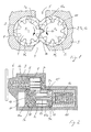
- FIG. 1 shows an external gear pump in a cross section.
- a feed chamber is formed in the two externally toothed conveying rotors 1 and 2 in the form of externally toothed gears about parallel axes of rotation R are rotatably supported 1 and R 2.
- the conveying rotor 1 is rotationally driven, for example, by the crankshaft of an internal combustion engine of a motor vehicle.
- the conveyor rotors 1 and 2 are meshed with each other, so that in a rotary drive of the conveyor rotor 1 of the thus meshing conveyor rotor 2 is also rotationally driven.
- the housing part 3 forms the conveying rotors 1 and 2 facing in the radial direction in each case a radial sealing surface 9, which wraps around the respective conveying rotor 1 or 2 on the circumference, forming a narrow radial sealing gap.
- the housing 3, 6 further forms on each end face of the conveyor rotor 1 and this axially facing an axial sealing surface, of which in Figure 1, the sealing surface 7 can be seen.
- the conveying rotor 2 is axially facing at its two end faces each formed a further axial sealing surface, of which in cross section of Figure 1, the sealing surface 17 can be seen.
- the conveyor rotor 2 assumes an axial position with an axial overlap, ie engagement length, which is already reduced compared to the maximum engagement length.
- the conveyor rotor 2 is part of an adjustment consisting of a bearing pin 14, an actuator 15, an actuator 16 and the rotatably mounted between the actuators 15 and 16 on the bearing pin 14 conveyor rotor 2.
- the bearing pin 14 connects the actuators 15 and 16 torsionally rigid with each other.
- the actuator 16 forms the conveying rotor 2 facing the axial sealing surface 17.
- the actuator 15 forms the other axial sealing surface 18.
- the entire adjustment is mounted in a sliding chamber of the pump housing 3, 6 axially displaceable back and forth against rotation.
- the housing is formed by the housing part 3 and the housing cover 6 firmly connected thereto.
- the housing cover 6 is formed with a base, whose end surface facing the conveying rotor 1 forms the sealing surface 7.
- the housing part 3 forms on the opposite end side of the conveyor rotor 1 axially facing the fourth axial sealing surface 8.
- the sealing surface 8 is provided on its side facing the adjusting unit with a circular segment-shaped cutout for the actuator 15.
- the actuator 16 is provided on its side facing the conveyor rotor 1 with a circular segment-shaped cutout for the sealing surface 7 forming the base 6.
- the sealing surface 7 corresponds to the sealing surface 8 and corresponds to the sealing surface 17 of the sealing surface 18th
- the adjusting members 15 and 16 of the embodiment are adjusting piston.
- the sliding chamber in which the adjusting unit is axially movable back and forth, comprises a limited from the back of the actuator 15 subspace 10 and a limited from the back of the actuator 16 subspace 11.
- the subspace 11 is connected to the high pressure side of the pump and is constantly pressurized there with branched pressure fluid, which thus acts on the back of the actuator 16.
- a mechanical compression spring is arranged as the elastic member 12, the elastic force acts on the back of the actuator 16.
- the elastic member 12 counteracts acting in the subspace 11 on the actuator 16 pressing force.
- the regulation of such external gear pumps is known and therefore needs no explanation.
- the regulation may in particular be in accordance with DE 102 22 1.31 B4 be designed.
- the sealing surfaces 7, 8, 17 and 18 are each provided on the high pressure side with a discharge pocket.
- Relief pockets are formed only on the high pressure side.
- the housing part 3 guides the actuators 15 and 16 in sliding contact.
- the housing part 3 form a raceway 3a and the housing part 3 together with the cover 6 a raceway 3b, 6b.
- the actuators 15 and 16 each form an actuator slide surface 15a and 16a on its outer peripheral surface. More specifically, in the sliding contact, the raceway 3a and the actuator sliding surface 15a on the one hand, and the raceway 3b, 6b and the actuator sliding surface 16a on the other hand.
- a special sliding material forms at least one of the sliding partners of the relevant friction system.
- either the raceway 3a or the actuator slide surface 15a may be formed by the sliding material.
- the same sliding material may further constitute both the raceway 3a and the actuator sliding surface 15a.
- the two sliding surfaces 3a and 15a can each be formed by a different sliding material. The same applies with respect to the other friction system 3b, 6b / 16a. If only one of the sliding partners of the respective friction system consists of the sliding material, the same sliding material is expediently used in each case. If both friction partners consist of a sliding material, the actuator sliding surfaces 15a and 16a are each formed by the same sliding material or the raceways 3a, 3b and 6b are each formed by the same sliding material.
- Example 1 the housing part 3 and the lid 6 are each die-cast from the same aluminum alloy, namely AlSi9Cu3.
- the alloy may contain a small amount of Fe.
- the raceways 3a, 3b and 6b are obtained by mechanical machining accurately.
- the actuators 15 and 16 are each molded as a whole from the specified plastic sliding material.
- the sliding surfaces 15a and 16a are accurately produced by mechanical processing.
- the housing part 3 and the cover 6 correspond to Example 1.
- the actuators 15 and 16 each consist of the same Al alloy, preferably AlSi8Cu3. They are formed from a cast semi-finished aluminum alloy by extrusion. Subsequently, at least the circumferential surfaces are each provided with a sliding layer of the plastic sliding material. Instead of molding the blanks of the actuators 15 and 16 by extrusion, the blanks can be formed by sintering and calibrating. The extruded or calibrated blanks are heated and overmolded in a mold with the plastic sliding material, preferably completely enveloped.
- Housing part 3 and cover 6 each made of AlSi9Cu3 (Fe) die cast Runways 3a, 3b and 6b: Hardcoat smooth (HC-GL sliding layer, preferably with PTFE impregnation)
- Actuators 15 and 16 Extruded parts of semi-finished aluminum casting as support material, for example AlSi8Cu3 Sliding surfaces 15a and 16a: Hardcoat smooth (HC-GL sliding layer, preferably with PTFE impregnation)
- the housing part 3 and the cover 6 correspond to Example 1.
- the actuators 15 and 16 each consist of the same aluminum alloy, preferably AlSi8Cu3. They are either formed from a cast semi-finished product by extrusion or alternatively by sintering and calibration. Subsequently, the actuator blanks are anodized at least at their respective peripheral surface forming the sliding surface 15a and 16a.
- the electrolyte used is a mixture of oxalic acid and additives, so that a sliding layer of Al 2 O 3 hardcoat smooth forms on the outer peripheral surfaces. Preferably, the sliding layer with PTFE impregnated.
- the raceways 3a, 3b and 6b are also formed in the same way each as a HC-GL sliding layer, preferably as a PTFE-impregnated sliding layer.
- Housing part 3 and cover 6 each made of AlSi9Cu3 (Fe) die cast Runways .3a, .3b and 6b: HC-slip layer
- Actuators 15 and 16 Steel, for example 30CrMoV9, as a carrier material
- Sliding surfaces 15a and 16a nitrided steel
- the HC overlay may be PTFE impregnated.
- the actuators 15 and 16 are formed of steel and nitrided on the surface, at least on the outer peripheral surfaces.
- Housing part 3 and cover 6 AlSi8Cu3 Sand casting or chill casting Actuators 15 and 16; Extruded parts of semi-finished aluminum casting as support material, for example AlSi8Cu3 Sliding surfaces 15a and 16a: Hardcoat Smooth (HC-Gl Sliding Layer)
- the housing part 3 and the lid 6 are each formed of AlSi8Cu3 in sand casting or chill casting.
- the raceways 3a, .3b and 6b are produced accurately by mechanical machining.
- the actuators 15 and 16 are each formed of extruded aluminum semi-finished by extrusion molding and anodized.
- As the electrolyte a mixture of oxalic acid and additives is used, so that on the outer peripheral surfaces depending on a sliding layer Al 2 O 3 -Hardcoat-Smooth forms (HC-GL sliding layer).
- the HC-GL overlay preferably contains PTFE.
- HC-ceramic or HC-smooth ceramic also forms the raceways 3a, 3b and 6b, wherein also there the ceramic can advantageously be impregnated PTFE.
- the manufacturing method and choice of material of the last embodiment is particularly suitable for smaller series, while the molding of the housing parts 3 and 6 in die casting for large series is the better choice, metal-ceramic overlays are particularly suitable for use in friction systems with light metal sand cast or - chill cast or in general Alloy cast alloys that solidify in thermodynamic equilibrium or near thermodynamic equilibrium.
- the smaller ⁇ -mixed crystals, for example AlSi, of the die-cast microstructure due to the shorter cooling time present problems such as fine abrasive grains for metal oxide ceramic sliding layers.
- sliding-modified, temperature-resistant thermoplastics are the better choice, or both sliding partners should each have an HC or HC-GL sliding layer.
- both sanding or Kokillengussge both sliding from a sliding material low adhesive energy.
Landscapes
- Engineering & Computer Science (AREA)
- Mechanical Engineering (AREA)
- General Engineering & Computer Science (AREA)
- Details And Applications Of Rotary Liquid Pumps (AREA)
- Rotary Pumps (AREA)
Priority Applications (3)
| Application Number | Priority Date | Filing Date | Title |
|---|---|---|---|
| PL07106407T PL1847713T3 (pl) | 2006-04-19 | 2007-04-18 | Regulowana pompa wirnikowa ze zmniejszonym zużyciem |
| EP10178105.2A EP2327881B1 (fr) | 2006-04-19 | 2007-04-18 | Pompe rotative réglable dotée d'une réduction d'usure |
| EP18170712.6A EP3376031B1 (fr) | 2006-04-19 | 2007-04-18 | Pompe de rotation ajustable à usure réduite |
Applications Claiming Priority (1)
| Application Number | Priority Date | Filing Date | Title |
|---|---|---|---|
| DE102006018124A DE102006018124A1 (de) | 2006-04-19 | 2006-04-19 | Verstellbare Rotationspumpe mit Verschleißminderung |
Related Child Applications (4)
| Application Number | Title | Priority Date | Filing Date |
|---|---|---|---|
| EP10178105.2A Division EP2327881B1 (fr) | 2006-04-19 | 2007-04-18 | Pompe rotative réglable dotée d'une réduction d'usure |
| EP10178105.2A Previously-Filed-Application EP2327881B1 (fr) | 2006-04-19 | 2007-04-18 | Pompe rotative réglable dotée d'une réduction d'usure |
| EP18170712.6A Division EP3376031B1 (fr) | 2006-04-19 | 2007-04-18 | Pompe de rotation ajustable à usure réduite |
| EP10178105.2 Division-Into | 2010-09-21 |
Publications (3)
| Publication Number | Publication Date |
|---|---|
| EP1847713A2 true EP1847713A2 (fr) | 2007-10-24 |
| EP1847713A3 EP1847713A3 (fr) | 2008-06-11 |
| EP1847713B1 EP1847713B1 (fr) | 2011-03-02 |
Family
ID=38283219
Family Applications (3)
| Application Number | Title | Priority Date | Filing Date |
|---|---|---|---|
| EP07106407A Active EP1847713B1 (fr) | 2006-04-19 | 2007-04-18 | Pompe rotative réglable à usure réduite |
| EP18170712.6A Not-in-force EP3376031B1 (fr) | 2006-04-19 | 2007-04-18 | Pompe de rotation ajustable à usure réduite |
| EP10178105.2A Active EP2327881B1 (fr) | 2006-04-19 | 2007-04-18 | Pompe rotative réglable dotée d'une réduction d'usure |
Family Applications After (2)
| Application Number | Title | Priority Date | Filing Date |
|---|---|---|---|
| EP18170712.6A Not-in-force EP3376031B1 (fr) | 2006-04-19 | 2007-04-18 | Pompe de rotation ajustable à usure réduite |
| EP10178105.2A Active EP2327881B1 (fr) | 2006-04-19 | 2007-04-18 | Pompe rotative réglable dotée d'une réduction d'usure |
Country Status (7)
| Country | Link |
|---|---|
| US (3) | US20070248481A1 (fr) |
| EP (3) | EP1847713B1 (fr) |
| JP (1) | JP4662559B2 (fr) |
| AT (2) | ATE500423T1 (fr) |
| DE (4) | DE102006018124A1 (fr) |
| HU (1) | HUE040650T2 (fr) |
| PL (1) | PL1847713T3 (fr) |
Cited By (1)
| Publication number | Priority date | Publication date | Assignee | Title |
|---|---|---|---|---|
| WO2010145862A3 (fr) * | 2009-06-16 | 2011-10-27 | Robert Bosch Gmbh | Pompe à carburant |
Families Citing this family (14)
| Publication number | Priority date | Publication date | Assignee | Title |
|---|---|---|---|---|
| DE102006018124A1 (de) * | 2006-04-19 | 2007-10-25 | Schwäbische Hüttenwerke Automotive GmbH & Co. KG | Verstellbare Rotationspumpe mit Verschleißminderung |
| JP5064886B2 (ja) * | 2007-05-21 | 2012-10-31 | 株式会社Tbk | ギヤポンプ |
| WO2010001764A1 (fr) * | 2008-07-03 | 2010-01-07 | 株式会社小松製作所 | Pompe à engrenages et à déplacement variable |
| DE102010004594B4 (de) * | 2010-01-14 | 2017-05-24 | Audi Ag | Regelölpumpe |
| DE102010005984B4 (de) * | 2010-01-28 | 2013-11-28 | Audi Ag | Regelölpumpe |
| DE102010020356A1 (de) | 2010-05-12 | 2011-11-17 | Audi Ag | Schmiermittelpumpe, Regelkolben |
| DE102010038430B4 (de) * | 2010-07-26 | 2012-12-06 | Schwäbische Hüttenwerke Automotive GmbH | Verdrängerpumpe mit Absaugnut |
| DE102010046941A1 (de) * | 2010-09-29 | 2012-03-29 | Wittenstein Ag | Tribologisches System |
| DE102011104049A1 (de) | 2011-06-11 | 2012-12-27 | Volkswagen Aktiengesellschaft | Pumpe |
| US9429149B2 (en) * | 2012-05-15 | 2016-08-30 | Sabic Global Technologies B.V. | Polyetherimide pump |
| KR102003107B1 (ko) * | 2015-08-12 | 2019-07-24 | 장순길 | 가변 용량 펌프 |
| DE102017117787A1 (de) * | 2017-08-04 | 2019-02-07 | Schwäbische Hüttenwerke Automotive GmbH | Verstellbare Außenzahnradpumpe |
| DE102019106660A1 (de) | 2019-03-15 | 2020-09-17 | Wagner Gmbh & Co. Kg | Steuerventil mit einer Anschlussfläche für mehrere Ventilports |
| CN112518239B (zh) | 2020-11-13 | 2022-02-08 | 浙江海洋大学 | 螺杆泵转子转模挤压成型工艺 |
Citations (1)
| Publication number | Priority date | Publication date | Assignee | Title |
|---|---|---|---|---|
| DE10222131B4 (de) | 2002-05-17 | 2005-05-12 | SCHWäBISCHE HüTTENWERKE GMBH | Verdrängerpumpe mit Fördervolumenverstellung |
Family Cites Families (35)
| Publication number | Priority date | Publication date | Assignee | Title |
|---|---|---|---|---|
| DE838826C (de) * | 1949-02-23 | 1952-05-12 | Bayer Ag | Verfahren zur Herstellung von Formkoerpern |
| US2621166A (en) * | 1949-02-23 | 1952-12-09 | Bayer Ag | Synthetic polymers |
| DE831772C (de) * | 1952-11-18 | 1952-02-18 | Bayer Ag | Verfahren zur Herstellung hochmolekularer vernetzter Kunststoffe |
| US2879248A (en) * | 1954-04-13 | 1959-03-24 | Bayer Ag | Method of making copolymer of diisocyanate modified polyester and vinylidene monomer |
| US2897248A (en) | 1956-06-06 | 1959-07-28 | Standard Oil Co | Alkylation |
| US3015283A (en) * | 1958-11-24 | 1962-01-02 | Bayer Ag | Gear pumps and motors |
| US4222718A (en) * | 1978-03-09 | 1980-09-16 | Rexnord Inc. | Linear motion thrust block for hydraulic pumps and motors |
| DE3018974A1 (de) * | 1980-05-17 | 1981-11-26 | Karl Schmidt Gmbh, 7107 Neckarsulm | Gleitlagerwerkstoff |
| JPS60197880A (ja) * | 1984-03-19 | 1985-10-07 | Aisin Seiki Co Ltd | 複合メッキ被膜 |
| SE463829B (sv) * | 1985-03-15 | 1991-01-28 | Svenska Rotor Maskiner Ab | Skruvrotormaskin med aatminstone en rotor bestaaende av plastmaterial |
| JPS61266451A (ja) * | 1985-05-21 | 1986-11-26 | Daido Metal Kogyo Kk | 摺動部材用組成物 |
| DE3528651A1 (de) * | 1985-08-09 | 1987-02-19 | Rohs Hans Guenther Prof Dr Ing | Zahnradpumpe |
| DE3534242A1 (de) * | 1985-09-26 | 1987-03-26 | Kolbenschmidt Ag | Wartungsfreier mehrschicht-gleitlagerwerkstoff |
| JP2967245B2 (ja) * | 1991-08-22 | 1999-10-25 | 株式会社日立製作所 | 無給水ポンプ |
| US5165881A (en) * | 1991-09-16 | 1992-11-24 | Opcon Autorotor Ab | Rotor for a screw rotor machine |
| DE4200305C2 (de) * | 1992-01-09 | 1995-06-08 | Glyco Metall Werke | Regelbare Flügelzellenpumpe in kompakter Bauweise |
| JPH05230283A (ja) * | 1992-02-20 | 1993-09-07 | Bando Chem Ind Ltd | 空気動圧機器用摺動部材 |
| US5554020A (en) * | 1994-10-07 | 1996-09-10 | Ford Motor Company | Solid lubricant coating for fluid pump or compressor |
| EP0718256B1 (fr) * | 1994-12-23 | 1999-06-30 | Maruwa Ceramic Co., Ltd. | Pièce coulissante et procédé pour sa fabrication |
| US5879791A (en) * | 1995-10-02 | 1999-03-09 | Daido Metal Company Ltd. | Wet type sliding apparatus comprising thrust bearing |
| US6461128B2 (en) * | 1996-04-24 | 2002-10-08 | Steven M. Wood | Progressive cavity helical device |
| ES2192242T3 (es) | 1996-12-04 | 2003-10-01 | Siegfried A Dipl-Ing Eisenmann | Bomba anular de engranajes continuamente variable. |
| DE19847132C2 (de) * | 1998-10-13 | 2001-05-31 | Schwaebische Huettenwerke Gmbh | Außenzahnradpumpe mit Fördervolumenbegrenzung |
| US20010024618A1 (en) * | 1999-12-01 | 2001-09-27 | Winmill Len F. | Adjustable-displacement gear pump |
| DE20020695U1 (de) * | 2000-12-06 | 2001-02-22 | Breed Automotive Technology, Inc., Lakeland, Fla. | Vorrichtung zum Bewegen eines Stellelementes |
| JP2002242852A (ja) | 2001-02-19 | 2002-08-28 | Mitsubishi Rayon Co Ltd | ギヤポンプ |
| US6604922B1 (en) * | 2002-03-14 | 2003-08-12 | Schlumberger Technology Corporation | Optimized fiber reinforced liner material for positive displacement drilling motors |
| JP4285634B2 (ja) * | 2003-02-20 | 2009-06-24 | 大同メタル工業株式会社 | 摺動部材 |
| US6867532B2 (en) * | 2003-07-17 | 2005-03-15 | The Brady Group Inc. | Long life piezoelectric drive and components |
| KR101222882B1 (ko) * | 2003-09-03 | 2013-01-17 | 가부시키가이샤 고마쓰 세이사쿠쇼 | 소결 슬라이딩 재료, 슬라이딩 부재, 연결장치 및 슬라이딩부재가 적용되는 장치 |
| DE102004012726A1 (de) * | 2004-03-16 | 2005-10-06 | Voigt, Dieter, Dipl.-Ing. | Durckanhebung für Regelölpumpen |
| DE102004030321A1 (de) * | 2004-06-23 | 2006-01-19 | Volkswagen Ag | Zahnradpumpe |
| DE102004033968B4 (de) * | 2004-07-14 | 2012-02-02 | Ks Kolbenschmidt Gmbh | Verwendung einer Beschichtung zur Beschichtung von hochbelastbaren tribologischen Oberflächen von bewegten Bauteilen |
| US20060111501A1 (en) * | 2004-11-19 | 2006-05-25 | General Electric Company | Thermoplastic wear resistant compositions, methods of manufacture thereof and articles containing the same |
| DE102006018124A1 (de) * | 2006-04-19 | 2007-10-25 | Schwäbische Hüttenwerke Automotive GmbH & Co. KG | Verstellbare Rotationspumpe mit Verschleißminderung |
-
2006
- 2006-04-19 DE DE102006018124A patent/DE102006018124A1/de not_active Withdrawn
-
2007
- 2007-04-18 HU HUE10178105A patent/HUE040650T2/hu unknown
- 2007-04-18 JP JP2007109912A patent/JP4662559B2/ja not_active Expired - Fee Related
- 2007-04-18 EP EP07106407A patent/EP1847713B1/fr active Active
- 2007-04-18 AT AT07106407T patent/ATE500423T1/de active
- 2007-04-18 PL PL07106407T patent/PL1847713T3/pl unknown
- 2007-04-18 DE DE10178105T patent/DE10178105T8/de active Active
- 2007-04-18 EP EP18170712.6A patent/EP3376031B1/fr not_active Not-in-force
- 2007-04-18 EP EP10178105.2A patent/EP2327881B1/fr active Active
- 2007-04-18 DE DE502007006577T patent/DE502007006577D1/de active Active
- 2007-04-18 DE DE202007018987U patent/DE202007018987U1/de not_active Expired - Lifetime
- 2007-04-19 US US11/737,397 patent/US20070248481A1/en not_active Abandoned
-
2010
- 2010-08-13 AT AT0051210U patent/AT11651U1/de not_active IP Right Cessation
-
2011
- 2011-04-04 US US13/079,270 patent/US8186982B2/en not_active Expired - Fee Related
-
2012
- 2012-05-04 US US13/464,206 patent/US8770955B2/en active Active
Patent Citations (1)
| Publication number | Priority date | Publication date | Assignee | Title |
|---|---|---|---|---|
| DE10222131B4 (de) | 2002-05-17 | 2005-05-12 | SCHWäBISCHE HüTTENWERKE GMBH | Verdrängerpumpe mit Fördervolumenverstellung |
Cited By (2)
| Publication number | Priority date | Publication date | Assignee | Title |
|---|---|---|---|---|
| WO2010145862A3 (fr) * | 2009-06-16 | 2011-10-27 | Robert Bosch Gmbh | Pompe à carburant |
| CN102498297A (zh) * | 2009-06-16 | 2012-06-13 | 罗伯特·博世有限公司 | 具有溢流阀和旁路阀的燃料泵 |
Also Published As
| Publication number | Publication date |
|---|---|
| EP3376031B1 (fr) | 2021-12-22 |
| EP1847713B1 (fr) | 2011-03-02 |
| US20110182760A1 (en) | 2011-07-28 |
| DE202007018987U1 (de) | 2010-05-27 |
| HUE040650T2 (hu) | 2019-03-28 |
| US20120219448A1 (en) | 2012-08-30 |
| US20070248481A1 (en) | 2007-10-25 |
| DE10178105T1 (de) | 2012-09-06 |
| EP2327881A3 (fr) | 2014-03-26 |
| DE102006018124A1 (de) | 2007-10-25 |
| US8770955B2 (en) | 2014-07-08 |
| JP4662559B2 (ja) | 2011-03-30 |
| PL1847713T3 (pl) | 2011-06-30 |
| AT11651U1 (de) | 2011-02-15 |
| DE10178105T8 (de) | 2013-04-25 |
| EP1847713A3 (fr) | 2008-06-11 |
| EP3376031A1 (fr) | 2018-09-19 |
| JP2007285300A (ja) | 2007-11-01 |
| US8186982B2 (en) | 2012-05-29 |
| ATE500423T1 (de) | 2011-03-15 |
| EP2327881B1 (fr) | 2018-05-30 |
| DE502007006577D1 (de) | 2011-04-14 |
| EP2327881A2 (fr) | 2011-06-01 |
Similar Documents
| Publication | Publication Date | Title |
|---|---|---|
| EP1847713B1 (fr) | Pompe rotative réglable à usure réduite | |
| DE69519712T2 (de) | Fluidpumpe oder -verdichter mit gesteigerter Leistung | |
| DE4111110C3 (de) | Rotationskolbenmaschine, insbesondere Schraubenkompressor oder Schraubenvakuumpumpe | |
| EP1951443B1 (fr) | Composant, en particulier une pièce moulée comprenant un revêtement | |
| WO2015097159A1 (fr) | Couche de vernis de glissement et matériau composite multicouche pour palier lisse, comprenant une telle couche | |
| DE102012223042A1 (de) | Gleitlagerverbundwerkstoff | |
| DE102014102643A1 (de) | Rotationspumpe mit Kunststoffverbundstruktur | |
| RU2147699C1 (ru) | Способ изготовления подшипника скольжения | |
| DE19528910C2 (de) | Taumelscheibenverdichter | |
| AT501811B1 (de) | Lagerelement | |
| WO2004076708A1 (fr) | Procede de production d'une surface de glissement | |
| DE102015223452A1 (de) | Flügelzellenpumpe | |
| DE2421906C2 (de) | Drehkolbenluftpumpe | |
| DE112015000189B4 (de) | Doppelköpfiger Taumelplattenkompressor mit Gleitlager aus porös gesinterten Material und Verfahren zur Herstellung eines Zylinderblocks | |
| DE102008031730A1 (de) | Lagergehäuse und Abgasturbolader für eine Brennkraftmaschine | |
| DE102010064130A1 (de) | Axialscheibe und Zahnradpumpe mit Axialscheibe | |
| DE202007017339U1 (de) | Kolbenmaschine | |
| DE102009020109A1 (de) | Hydrostatische Verdrängermaschine | |
| EP3617512B1 (fr) | Pompe à vide du distributeur rotatif | |
| DE102009038326A1 (de) | Kolben für eine Axialkolbenpumpe und Axialkolbenpumpe | |
| WO2004109110A1 (fr) | Pompe a engrenages | |
| DE102010004594B4 (de) | Regelölpumpe | |
| DE102017117787A1 (de) | Verstellbare Außenzahnradpumpe | |
| DE102009021067A1 (de) | Dünnwandige Einlage für einen Zylinder einer Kolbenmaschine und eine Zylinderlaufbuchse, Zylinder und Motorblock einer Kolbenmaschine, sowie Verfahren zu deren Herstellung | |
| DE3015040C2 (de) | Rotationsverdrängerpumpe |
Legal Events
| Date | Code | Title | Description |
|---|---|---|---|
| PUAI | Public reference made under article 153(3) epc to a published international application that has entered the european phase |
Free format text: ORIGINAL CODE: 0009012 |
|
| AK | Designated contracting states |
Kind code of ref document: A2 Designated state(s): AT BE BG CH CY CZ DE DK EE ES FI FR GB GR HU IE IS IT LI LT LU LV MC MT NL PL PT RO SE SI SK TR |
|
| AX | Request for extension of the european patent |
Extension state: AL BA HR MK YU |
|
| REG | Reference to a national code |
Ref country code: SE Ref legal event code: TRCL |
|
| PUAL | Search report despatched |
Free format text: ORIGINAL CODE: 0009013 |
|
| AK | Designated contracting states |
Kind code of ref document: A3 Designated state(s): AT BE BG CH CY CZ DE DK EE ES FI FR GB GR HU IE IS IT LI LT LU LV MC MT NL PL PT RO SE SI SK TR |
|
| AX | Request for extension of the european patent |
Extension state: AL BA HR MK RS |
|
| EL | Fr: translation of claims filed | ||
| 17P | Request for examination filed |
Effective date: 20081028 |
|
| 17Q | First examination report despatched |
Effective date: 20081127 |
|
| AKX | Designation fees paid |
Designated state(s): DE ES FR GB IT NL SE |
|
| RAP1 | Party data changed (applicant data changed or rights of an application transferred) |
Owner name: SCHWAEBISCHE HUETTENWERKE AUTOMOTIVE GMBH |
|
| RBV | Designated contracting states (corrected) |
Designated state(s): AT BE BG CH CY CZ DE DK EE ES FI FR GB GR HU IE IS IT LI LT LU LV MC MT NL PL PT RO SE SI SK TR |
|
| GRAP | Despatch of communication of intention to grant a patent |
Free format text: ORIGINAL CODE: EPIDOSNIGR1 |
|
| GRAS | Grant fee paid |
Free format text: ORIGINAL CODE: EPIDOSNIGR3 |
|
| GRAA | (expected) grant |
Free format text: ORIGINAL CODE: 0009210 |
|
| AK | Designated contracting states |
Kind code of ref document: B1 Designated state(s): AT BE BG CH CY CZ DE DK EE ES FI FR GB GR HU IE IS IT LI LT LU LV MC MT NL PL PT RO SE SI SK TR |
|
| REG | Reference to a national code |
Ref country code: GB Ref legal event code: FG4D Free format text: NOT ENGLISH |
|
| REG | Reference to a national code |
Ref country code: CH Ref legal event code: EP Ref country code: SE Ref legal event code: TRGR |
|
| REG | Reference to a national code |
Ref country code: IE Ref legal event code: FG4D Free format text: LANGUAGE OF EP DOCUMENT: GERMAN |
|
| REF | Corresponds to: |
Ref document number: 502007006577 Country of ref document: DE Date of ref document: 20110414 Kind code of ref document: P |
|
| REG | Reference to a national code |
Ref country code: DE Ref legal event code: R096 Ref document number: 502007006577 Country of ref document: DE Effective date: 20110414 |
|
| REG | Reference to a national code |
Ref country code: PL Ref legal event code: T3 |
|
| REG | Reference to a national code |
Ref country code: NL Ref legal event code: VDEP Effective date: 20110302 |
|
| PG25 | Lapsed in a contracting state [announced via postgrant information from national office to epo] |
Ref country code: ES Free format text: LAPSE BECAUSE OF FAILURE TO SUBMIT A TRANSLATION OF THE DESCRIPTION OR TO PAY THE FEE WITHIN THE PRESCRIBED TIME-LIMIT Effective date: 20110613 Ref country code: LV Free format text: LAPSE BECAUSE OF FAILURE TO SUBMIT A TRANSLATION OF THE DESCRIPTION OR TO PAY THE FEE WITHIN THE PRESCRIBED TIME-LIMIT Effective date: 20110302 Ref country code: LT Free format text: LAPSE BECAUSE OF FAILURE TO SUBMIT A TRANSLATION OF THE DESCRIPTION OR TO PAY THE FEE WITHIN THE PRESCRIBED TIME-LIMIT Effective date: 20110302 Ref country code: GR Free format text: LAPSE BECAUSE OF FAILURE TO SUBMIT A TRANSLATION OF THE DESCRIPTION OR TO PAY THE FEE WITHIN THE PRESCRIBED TIME-LIMIT Effective date: 20110603 |
|
| LTIE | Lt: invalidation of european patent or patent extension |
Effective date: 20110302 |
|
| PG25 | Lapsed in a contracting state [announced via postgrant information from national office to epo] |
Ref country code: FI Free format text: LAPSE BECAUSE OF FAILURE TO SUBMIT A TRANSLATION OF THE DESCRIPTION OR TO PAY THE FEE WITHIN THE PRESCRIBED TIME-LIMIT Effective date: 20110302 Ref country code: CY Free format text: LAPSE BECAUSE OF FAILURE TO SUBMIT A TRANSLATION OF THE DESCRIPTION OR TO PAY THE FEE WITHIN THE PRESCRIBED TIME-LIMIT Effective date: 20110302 Ref country code: NL Free format text: LAPSE BECAUSE OF FAILURE TO SUBMIT A TRANSLATION OF THE DESCRIPTION OR TO PAY THE FEE WITHIN THE PRESCRIBED TIME-LIMIT Effective date: 20110302 Ref country code: SI Free format text: LAPSE BECAUSE OF FAILURE TO SUBMIT A TRANSLATION OF THE DESCRIPTION OR TO PAY THE FEE WITHIN THE PRESCRIBED TIME-LIMIT Effective date: 20110302 Ref country code: BG Free format text: LAPSE BECAUSE OF FAILURE TO SUBMIT A TRANSLATION OF THE DESCRIPTION OR TO PAY THE FEE WITHIN THE PRESCRIBED TIME-LIMIT Effective date: 20110602 |
|
| REG | Reference to a national code |
Ref country code: HU Ref legal event code: AG4A Ref document number: E010953 Country of ref document: HU Ref country code: IE Ref legal event code: FD4D |
|
| BERE | Be: lapsed |
Owner name: SCHWABISCHE HUTTENWERKE AUTOMOTIVE G.M.B.H. Effective date: 20110430 |
|
| PG25 | Lapsed in a contracting state [announced via postgrant information from national office to epo] |
Ref country code: EE Free format text: LAPSE BECAUSE OF FAILURE TO SUBMIT A TRANSLATION OF THE DESCRIPTION OR TO PAY THE FEE WITHIN THE PRESCRIBED TIME-LIMIT Effective date: 20110302 Ref country code: PT Free format text: LAPSE BECAUSE OF FAILURE TO SUBMIT A TRANSLATION OF THE DESCRIPTION OR TO PAY THE FEE WITHIN THE PRESCRIBED TIME-LIMIT Effective date: 20110704 Ref country code: IE Free format text: LAPSE BECAUSE OF FAILURE TO SUBMIT A TRANSLATION OF THE DESCRIPTION OR TO PAY THE FEE WITHIN THE PRESCRIBED TIME-LIMIT Effective date: 20110302 |
|
| PLBI | Opposition filed |
Free format text: ORIGINAL CODE: 0009260 |
|
| PG25 | Lapsed in a contracting state [announced via postgrant information from national office to epo] |
Ref country code: IS Free format text: LAPSE BECAUSE OF FAILURE TO SUBMIT A TRANSLATION OF THE DESCRIPTION OR TO PAY THE FEE WITHIN THE PRESCRIBED TIME-LIMIT Effective date: 20110702 Ref country code: SK Free format text: LAPSE BECAUSE OF FAILURE TO SUBMIT A TRANSLATION OF THE DESCRIPTION OR TO PAY THE FEE WITHIN THE PRESCRIBED TIME-LIMIT Effective date: 20110302 Ref country code: MC Free format text: LAPSE BECAUSE OF NON-PAYMENT OF DUE FEES Effective date: 20110430 Ref country code: RO Free format text: LAPSE BECAUSE OF FAILURE TO SUBMIT A TRANSLATION OF THE DESCRIPTION OR TO PAY THE FEE WITHIN THE PRESCRIBED TIME-LIMIT Effective date: 20110302 |
|
| REG | Reference to a national code |
Ref country code: CH Ref legal event code: PL |
|
| PLAB | Opposition data, opponent's data or that of the opponent's representative modified |
Free format text: ORIGINAL CODE: 0009299OPPO |
|
| 26 | Opposition filed |
Opponent name: VOLKSWAGEN AKTIENGESELLSCHAFT Effective date: 20111123 |
|
| PG25 | Lapsed in a contracting state [announced via postgrant information from national office to epo] |
Ref country code: MT Free format text: LAPSE BECAUSE OF FAILURE TO SUBMIT A TRANSLATION OF THE DESCRIPTION OR TO PAY THE FEE WITHIN THE PRESCRIBED TIME-LIMIT Effective date: 20110302 |
|
| R26 | Opposition filed (corrected) |
Opponent name: VOLKSWAGEN AKTIENGESELLSCHAFT Effective date: 20111123 |
|
| PG25 | Lapsed in a contracting state [announced via postgrant information from national office to epo] |
Ref country code: CH Free format text: LAPSE BECAUSE OF NON-PAYMENT OF DUE FEES Effective date: 20110430 Ref country code: LI Free format text: LAPSE BECAUSE OF NON-PAYMENT OF DUE FEES Effective date: 20110430 Ref country code: BE Free format text: LAPSE BECAUSE OF NON-PAYMENT OF DUE FEES Effective date: 20110430 |
|
| PLAX | Notice of opposition and request to file observation + time limit sent |
Free format text: ORIGINAL CODE: EPIDOSNOBS2 |
|
| REG | Reference to a national code |
Ref country code: DE Ref legal event code: R026 Ref document number: 502007006577 Country of ref document: DE Effective date: 20111123 |
|
| PLAF | Information modified related to communication of a notice of opposition and request to file observations + time limit |
Free format text: ORIGINAL CODE: EPIDOSCOBS2 |
|
| PLBB | Reply of patent proprietor to notice(s) of opposition received |
Free format text: ORIGINAL CODE: EPIDOSNOBS3 |
|
| PLAB | Opposition data, opponent's data or that of the opponent's representative modified |
Free format text: ORIGINAL CODE: 0009299OPPO |
|
| R26 | Opposition filed (corrected) |
Opponent name: VOLKSWAGEN AG Effective date: 20111123 |
|
| PLAB | Opposition data, opponent's data or that of the opponent's representative modified |
Free format text: ORIGINAL CODE: 0009299OPPO |
|
| R26 | Opposition filed (corrected) |
Opponent name: VOLKSWAGEN AG Effective date: 20111123 |
|
| PG25 | Lapsed in a contracting state [announced via postgrant information from national office to epo] |
Ref country code: LU Free format text: LAPSE BECAUSE OF NON-PAYMENT OF DUE FEES Effective date: 20110418 |
|
| PLBP | Opposition withdrawn |
Free format text: ORIGINAL CODE: 0009264 |
|
| PLAB | Opposition data, opponent's data or that of the opponent's representative modified |
Free format text: ORIGINAL CODE: 0009299OPPO |
|
| PLBD | Termination of opposition procedure: decision despatched |
Free format text: ORIGINAL CODE: EPIDOSNOPC1 |
|
| PLBM | Termination of opposition procedure: date of legal effect published |
Free format text: ORIGINAL CODE: 0009276 |
|
| STAA | Information on the status of an ep patent application or granted ep patent |
Free format text: STATUS: OPPOSITION PROCEDURE CLOSED |
|
| 27C | Opposition proceedings terminated |
Effective date: 20140316 |
|
| REG | Reference to a national code |
Ref country code: FR Ref legal event code: PLFP Year of fee payment: 10 |
|
| REG | Reference to a national code |
Ref country code: FR Ref legal event code: PLFP Year of fee payment: 11 |
|
| REG | Reference to a national code |
Ref country code: FR Ref legal event code: PLFP Year of fee payment: 12 |
|
| PGFP | Annual fee paid to national office [announced via postgrant information from national office to epo] |
Ref country code: PL Payment date: 20230321 Year of fee payment: 17 |
|
| P01 | Opt-out of the competence of the unified patent court (upc) registered |
Effective date: 20230515 |
|
| PGFP | Annual fee paid to national office [announced via postgrant information from national office to epo] |
Ref country code: IT Payment date: 20230426 Year of fee payment: 17 Ref country code: FR Payment date: 20230420 Year of fee payment: 17 Ref country code: DE Payment date: 20230420 Year of fee payment: 17 Ref country code: CZ Payment date: 20230412 Year of fee payment: 17 |
|
| PGFP | Annual fee paid to national office [announced via postgrant information from national office to epo] |
Ref country code: TR Payment date: 20230417 Year of fee payment: 17 Ref country code: SE Payment date: 20230420 Year of fee payment: 17 Ref country code: HU Payment date: 20230421 Year of fee payment: 17 Ref country code: AT Payment date: 20230420 Year of fee payment: 17 |
|
| PGFP | Annual fee paid to national office [announced via postgrant information from national office to epo] |
Ref country code: GB Payment date: 20230419 Year of fee payment: 17 |
|
| REG | Reference to a national code |
Ref country code: DE Ref legal event code: R119 Ref document number: 502007006577 Country of ref document: DE |
|
| REG | Reference to a national code |
Ref country code: SE Ref legal event code: EUG |
|
| REG | Reference to a national code |
Ref country code: AT Ref legal event code: MM01 Ref document number: 500423 Country of ref document: AT Kind code of ref document: T Effective date: 20240418 |
|
| GBPC | Gb: european patent ceased through non-payment of renewal fee |
Effective date: 20240418 |
|
| PG25 | Lapsed in a contracting state [announced via postgrant information from national office to epo] |
Ref country code: HU Free format text: LAPSE BECAUSE OF NON-PAYMENT OF DUE FEES Effective date: 20240419 |
|
| PG25 | Lapsed in a contracting state [announced via postgrant information from national office to epo] |
Ref country code: DE Free format text: LAPSE BECAUSE OF NON-PAYMENT OF DUE FEES Effective date: 20241105 |
|
| PG25 | Lapsed in a contracting state [announced via postgrant information from national office to epo] |
Ref country code: GB Free format text: LAPSE BECAUSE OF NON-PAYMENT OF DUE FEES Effective date: 20240418 |
|
| PG25 | Lapsed in a contracting state [announced via postgrant information from national office to epo] |
Ref country code: FR Free format text: LAPSE BECAUSE OF NON-PAYMENT OF DUE FEES Effective date: 20240430 |
|
| PG25 | Lapsed in a contracting state [announced via postgrant information from national office to epo] |
Ref country code: AT Free format text: LAPSE BECAUSE OF NON-PAYMENT OF DUE FEES Effective date: 20240418 |
|
| PG25 | Lapsed in a contracting state [announced via postgrant information from national office to epo] |
Ref country code: CZ Free format text: LAPSE BECAUSE OF NON-PAYMENT OF DUE FEES Effective date: 20240418 |
|
| PG25 | Lapsed in a contracting state [announced via postgrant information from national office to epo] |
Ref country code: HU Free format text: LAPSE BECAUSE OF NON-PAYMENT OF DUE FEES Effective date: 20240419 Ref country code: GB Free format text: LAPSE BECAUSE OF NON-PAYMENT OF DUE FEES Effective date: 20240418 Ref country code: FR Free format text: LAPSE BECAUSE OF NON-PAYMENT OF DUE FEES Effective date: 20240430 Ref country code: DE Free format text: LAPSE BECAUSE OF NON-PAYMENT OF DUE FEES Effective date: 20241105 Ref country code: CZ Free format text: LAPSE BECAUSE OF NON-PAYMENT OF DUE FEES Effective date: 20240418 Ref country code: AT Free format text: LAPSE BECAUSE OF NON-PAYMENT OF DUE FEES Effective date: 20240418 |
|
| PG25 | Lapsed in a contracting state [announced via postgrant information from national office to epo] |
Ref country code: PL Free format text: LAPSE BECAUSE OF NON-PAYMENT OF DUE FEES Effective date: 20240418 |
|
| PG25 | Lapsed in a contracting state [announced via postgrant information from national office to epo] |
Ref country code: IT Free format text: LAPSE BECAUSE OF NON-PAYMENT OF DUE FEES Effective date: 20240418 |
|
| PG25 | Lapsed in a contracting state [announced via postgrant information from national office to epo] |
Ref country code: SE Free format text: LAPSE BECAUSE OF NON-PAYMENT OF DUE FEES Effective date: 20240419 |