EP1849720B1 - Mobile vertikale Speichervorrichtung - Google Patents
Mobile vertikale Speichervorrichtung Download PDFInfo
- Publication number
- EP1849720B1 EP1849720B1 EP07300975.5A EP07300975A EP1849720B1 EP 1849720 B1 EP1849720 B1 EP 1849720B1 EP 07300975 A EP07300975 A EP 07300975A EP 1849720 B1 EP1849720 B1 EP 1849720B1
- Authority
- EP
- European Patent Office
- Prior art keywords
- frame
- ground
- mobile
- anchoring
- mobile frame
- Prior art date
- Legal status (The legal status is an assumption and is not a legal conclusion. Google has not performed a legal analysis and makes no representation as to the accuracy of the status listed.)
- Not-in-force
Links
- 238000004873 anchoring Methods 0.000 claims description 44
- 238000006073 displacement reaction Methods 0.000 claims description 33
- 238000013016 damping Methods 0.000 claims description 19
- 239000004020 conductor Substances 0.000 claims description 5
- 229910000831 Steel Inorganic materials 0.000 claims description 3
- 230000005540 biological transmission Effects 0.000 claims description 3
- 210000000078 claw Anatomy 0.000 claims description 3
- 239000010959 steel Substances 0.000 claims description 3
- 230000033001 locomotion Effects 0.000 description 10
- 239000000047 product Substances 0.000 description 5
- 230000000694 effects Effects 0.000 description 4
- 238000010276 construction Methods 0.000 description 2
- 230000006378 damage Effects 0.000 description 2
- 238000012423 maintenance Methods 0.000 description 2
- 230000000284 resting effect Effects 0.000 description 2
- 210000004027 cell Anatomy 0.000 description 1
- 230000000295 complement effect Effects 0.000 description 1
- 238000001514 detection method Methods 0.000 description 1
- 230000006866 deterioration Effects 0.000 description 1
- 239000000463 material Substances 0.000 description 1
- 238000012986 modification Methods 0.000 description 1
- 230000004048 modification Effects 0.000 description 1
- 230000001681 protective effect Effects 0.000 description 1
- 239000011265 semifinished product Substances 0.000 description 1
- 239000002689 soil Substances 0.000 description 1
- 238000006467 substitution reaction Methods 0.000 description 1
Images


Classifications
-
- B—PERFORMING OPERATIONS; TRANSPORTING
- B65—CONVEYING; PACKING; STORING; HANDLING THIN OR FILAMENTARY MATERIAL
- B65G—TRANSPORT OR STORAGE DEVICES, e.g. CONVEYORS FOR LOADING OR TIPPING, SHOP CONVEYOR SYSTEMS OR PNEUMATIC TUBE CONVEYORS
- B65G1/00—Storing articles, individually or in orderly arrangement, in warehouses or magazines
- B65G1/02—Storage devices
- B65G1/04—Storage devices mechanical
- B65G1/0442—Storage devices mechanical for elongated articles
-
- B—PERFORMING OPERATIONS; TRANSPORTING
- B65—CONVEYING; PACKING; STORING; HANDLING THIN OR FILAMENTARY MATERIAL
- B65G—TRANSPORT OR STORAGE DEVICES, e.g. CONVEYORS FOR LOADING OR TIPPING, SHOP CONVEYOR SYSTEMS OR PNEUMATIC TUBE CONVEYORS
- B65G1/00—Storing articles, individually or in orderly arrangement, in warehouses or magazines
- B65G1/02—Storage devices
- B65G1/04—Storage devices mechanical
- B65G1/10—Storage devices mechanical with relatively movable racks to facilitate insertion or removal of articles
-
- B—PERFORMING OPERATIONS; TRANSPORTING
- B65—CONVEYING; PACKING; STORING; HANDLING THIN OR FILAMENTARY MATERIAL
- B65G—TRANSPORT OR STORAGE DEVICES, e.g. CONVEYORS FOR LOADING OR TIPPING, SHOP CONVEYOR SYSTEMS OR PNEUMATIC TUBE CONVEYORS
- B65G2201/00—Indexing codes relating to handling devices, e.g. conveyors, characterised by the type of product or load being conveyed or handled
- B65G2201/02—Articles
- B65G2201/0214—Articles of special size, shape or weigh
- B65G2201/0217—Elongated
Definitions
- the present invention relates to the field of storage and handling of finished or semi-finished products, particularly in the form of long profiles, in particular by means of vertical storage devices, and relates to such a mobile vertical storage device. .
- Storage warehouses built specifically for this purpose and in which vertical storage devices are arranged parallel to their longitudinal axis with the possibility of moving on integrated rails in the floor of the warehouses are also known.
- Such devices require, however, a special infrastructure to be designed at the origin of the construction of the warehouse and are not conceivable, for example, for the equipment of a room to be provided with a relatively small number storage devices or partially allocated to other uses.
- US-A-3,563,180 discloses a mobile carriage guided on rails, one of which serves essentially linear guidance and the others serve as support.
- US-A-5,938,047 also describes guide means on rails.
- the object of the present invention is to overcome these disadvantages by proposing a mobile vertical storage device that can easily be installed in existing premises, without requiring heavy infrastructure work, and perfectly stabilized against possible pivoting with respect to a median vertical plane. , which could result in a complete reversal under unbalanced load or side impact.
- the mobile vertical storage device which consists essentially of a horizontal frame, on which are mounted, at regular intervals, horizontal support supports for receiving and storing long products, such as that profiles, is characterized in that the frame is movable and cooperates with a means of securing the ground and displacement along its longitudinal axis.
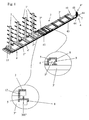
- the figure 1 The attached drawings show a storage device according to the invention, which essentially consists of a horizontal frame 2, on which are mounted, at regular intervals, horizontal supports 1 for receiving long products, such as profiles.
- the frame 2 is movable and cooperates with a means 3 of subjection to the ground and displacement along its longitudinal axis.
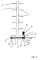
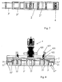
- the means 3 of subjection to the ground and displacement along its longitudinal axis is constituted, as shown more particularly by the Figures 2 to 4 of the accompanying drawings, on the one hand, by a frame 3 'ground anchor and by an intermediate frame 3 ", guided on the ground anchor frame 3' and forming a guide and a support of the mobile frame 2 and on the other hand, by a set 4 of displacement of the mobile frame 2 and the intermediate frame 3 ".
- the intermediate frame 3 is provided, at its end opposite to that which can be displaced towards the outside of the ground anchoring frame 3 ', of an end-of-travel limit stop cooperating with a element 6, projecting from said frame 3 'anchoring to the ground or directly attached to the ground.
- the intermediate frame 3 "remains guided on the ground anchor frame 3 'over part of its length and that the mobile frame 2 remains guided on the intermediate frame 3", when the mobile frame is fully extended by 3 'ground anchor frame, so that the stable maintenance of the movable frame 2 is ensured.
- the ground anchoring frame 3 'and the mobile frame 2 are advantageously made in the form of two superimposed angles, offset between them and each equipped with respective rollers 31' and 21 provided on their vertical flange and supported on profiles.
- longitudinal members 31 "equipping the corresponding edges of the intermediate frame 3", under the latter, the rollers 31 'and 21 being combined rollers with radial bearing and lateral guidance bearing on either side in the longitudinal sections 31 ", such that the mobile frame 2 can move on the intermediate frame 3 "without rubbing on the frame 3 'anchoring to the ground, a displacement of the intermediate frame assembly 3" and movable frame 2 is thus possible.
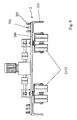
- the mobile frame 2 is equipped, as shown in FIG. figure 8 appended drawings, at its front end, of at least one pair of rollers with horizontal ground support axis 22, which is pivotally mounted, via a vertical axis bearing, on said movable frame 2.
- at least one pair of rollers with horizontal ground support axis 22 which is pivotally mounted, via a vertical axis bearing, on said movable frame 2.
- three pairs of rollers with a horizontal ground support axis 22 distributed uniformly over the width of the front part of the mobile frame 2 are provided.
- the intermediate frame 3 is advantageously provided, at its front end, with two pairs of rollers with a horizontal axis of ground support 32", which are pivotably mounted, each by means of a bearing with a vertical axis on said intermediate frame 3 ", on either side of its front end, in extension of the profiles 31" constituting it and at least partially in the axis of the combined rollers with radial bearing and lateral guidance 21 of the mobile frame 2.
- the slight deviations possible with respect to the longitudinal axis of the device can be compensated automatically by the rollers forming the pairs of rollers 32 "and 22 of said intermediate frame 3" and said movable frame 2, in correspondence with the rectilinear guiding effect ensured laterally on said frame 3 "and frame 2 by the combined rollers with radial bearing and lateral guidance 31 'and 21.
- the combined rollers with radial bearing and lateral guidance 21 of the mobile frame 2 are arranged on the vertical flanges of the angles forming the mobile frame 2, over part of the length of the latter extending to from the rear end of said movable frame 2 which corresponds to the overlap length of the movable frame 2 on the intermediate frame 3 ", when the movable frame 2 is in fully extended position relative to the frame 3 'ground anchor.
- the latter can first move alone on the intermediate frame 3 ", until it comes into abutment, by its combined rollers with radial bearing and lateral guidance 21 closer to its front end, with pairs of rollers horizontal axis of ground support 32 "of said intermediate frame 3", which is then driven in the output movement.
- the assembly 4 moving mobile chassis 2 and the intermediate frame 3 " ( Figures 1 to 3 ) is constituted by a portion 4 'integral with the movable frame 2 and a portion 4 "cooperating with the portion 4' and fixed on a support 7 which can be secured to the end of the frame 3 'ground anchor opposite to that output of the mobile frame 2.
- the assembly 4 which is integral with the movable frame 2 is formed in the form of a rack and the portion 4 "is constituted by a geared motor assembly 41 fixed on the support 7 of the end of the ground anchoring frame 3 ', driving a driving pinion 42 disposed at the opposite end of said ground anchoring frame 3' via a chain 43 and chain wheels 44.
- the mobile frame 2 is advantageously provided at its rear end, opposite to that of the exit from the ground anchor frame 3 ', of an end-of-travel 8 stop and retraction respectively cooperating with contacts.
- end-of-travel 9 and retraction 10 provided on the ground anchor frame 3 ', these end-of-travel contacts achieving automatic shutdown of the geared motor assembly 41 of the intermediate frame moving assembly 4 3 "and the mobile frame 2, on arrival in the extreme positions of the mobile frame 2.
- the assembly 4 for moving the mobile frame 2 and the intermediate frame 3 " is advantageously controlled by means of a control cabinet of the known type comprising at least one on / off switch and a safety switch, this control cabinet being connected, moreover, to the end limit travel stops 9 and retraction 10, as well as a means automatic stop safety device 11 provided at the end of the mobile frame 2 coming out of the intermediate frame 3 "and the ground anchor frame 3 ', this security means being, for example, a movable shield, provided with a switch.
- the portion 4" constituted by the geared motor assembly 41 fixed on the support 7 of the end of the frame 3 ' ground anchor, drives the drive pinion 42 disposed at the opposite end of said ground anchor frame 3 'through the chain 43 and the chain wheels 44 and said pinion, meshing with the rack forming the portion 4 'of this assembly and which is integral with the movable frame 2, carries the drive of said movable frame 2 towards its exit from the frame 3' anchoring to the ground.
- the mobile frame 2 is alone in motion, as explained above.
- the rollers combined radial range and lateral guidance 21 of the mobile frame 2 located at the front causes in their movement the intermediate frame 3 "for the continuation of the output of the movable frame 2.
- the mobile frame 2 has at its rear end, namely at the end remaining guided in the intermediate frame 3 ", a drive member 12 slightly projecting under said end of said mobile frame 2 and capable of cooperating with an end cross member 300 "of the intermediate frame 3.
- said mobile frame 2 drives the intermediate frame 3" into its retraction movement, as soon as it has performed, in said intermediate frame 3 ", a displacement corresponding to that of its initial displacement out of said frame 3".
- This displacement of the mobile frame 2 can be carried out, either completely while the intermediate frame 3 "is in its maximum output position, or partially with the displacement of the intermediate frame 3", the abutment of the drive element 12 providing only complete retraction of the intermediate frame 3 ".
- the ground anchoring frame 3 ' is rigidified transversely by means of flat crosspieces serving simultaneously for anchoring to the ground by means of lag bolts or the like, a crossbar connecting the rails forming the sides of this frame 3 simultaneously serving as a support for the projecting element 6 intended to cooperate with the end-of-travel limit stop 5 of the intermediate frame 3.
- This latter is stiffened transversely by means of connection profiles extending at a distance sufficient ground to ensure a displacement of the intermediate frame 3 "without risk of snagging with a fastening element of the frame 3 'anchoring or with the protruding element 6 of this frame intended to cooperate with the end stop 5.
- the mobile frame 2 is constituted by the longitudinal rails carrying the combined rollers with radial bearing and lateral guidance 21 cooperating with the longitudinal profiles 31 "of the intermediate frame 3", these rails being stiffened transversely by transverse profiled crosspieces 2 ", between the bases of the horizontal support supports 1 for receiving long products, such as profiles, are thus mounted so that the supports 1 are perfectly held on the mobile frame 2, which itself is guided in a perfectly rigid manner by relative to the ground, via the intermediate frame 3 "and the frame 3 'anchoring to the ground.
- the ground anchoring frame 3 ' is provided, on the one hand, with a means 431 for guiding the chain 43, as well as devices for adjusting the tension of the latter by means of the wheels. at the chain 44 and, secondly, at least one foldable protective sheath of the electrical conductors connecting the end-of-travel contacts 9 and 11.
- the invention has been described above with respect to a single mobile vertical storage device. However, it is possible to achieve, according to another characteristic of the invention, a drive of several mobile devices, successively or simultaneously by providing a clutch drive means.
- this clutch drive means can advantageously be constituted in the form of a dog clutch, whose jaw are fixedly mounted on the drive shaft of the geared motor assembly fixed on the support of the end of the anchoring frame on the ground, the claws being mounted idle and with the possibility of displacement by sliding by means of a control fork or the like on said drive shaft and being each provided with a wheel A chain drive chain for controlling the drive gear disposed at the opposite end of the ground anchor frame.
- a dog clutch is well known to those skilled in the art and is not explained in more detail.
- the moving assembly 4 of the movable frame 2 and the intermediate frame 3 is a geared motor assembly mounted on the distal portion of said movable frame 2 and directly driving at least one support and displacement roller 21 of the movable frame 2
- the geared motor assembly forming the moving assembly 4 of the mobile frame 2 and the intermediate frame 3 "causes a support and displacement roller 21 of the mobile frame 2 via its output shaft 420.
- Such an embodiment of the assembly 4 for moving the mobile frame 2 and the intermediate frame 3 "allows a simplification of the device, because the transmission elements of the movement are assembled in a compact assembly, which avoids the risks of
- the electrical conductors connecting the end-of-travel and electrical connection contacts of the moving assembly 4 of the mobile frame 2 and the intermediate frame 3 can also be grouped in an aerial cable suspended at regular intervals by means of eyelets with a steel cable hooked by its free end in the upper part of the support 1 horizontal supports the front end of the mobile frame 2, this cable mounted on an automatic winder provided on a support disposed at the rear end of the ground anchoring frame 3 ', so that all of the electrical conductors assigned to the device and to be connected near its front end can be easily guided and maintained without risk of deterioration through handling means or others.
- the assembly 4 for moving the movable frame 2 and the intermediate frame 3 may also be constituted by a telescopic jack supported by its yoke on the support 7 secured to the end of the anchoring frame 3 'on the ground opposite to that of the mobile frame 2 and its extreme cylinder rod on the distal cross member of the mobile frame 2, passing through corresponding passages of the intermediate frame 3 "and the mobile frame 2.
- the mobile vertical storage device may advantageously be provided, in addition, means for compensation of irregularities of the ground.
- the movable frame 2 is provided with at its front end of a first ground irregularity compensation means, in the form of a cross member 200 for receiving bearings of the ground support rollers 22 and / or of the support and displacement rollers 21, this crossmember 200 being movably connected, at its ends, to the longitudinal members 201 of the movable frame 2, by means of a ball bushing guide 202 and a damping device 203.
- a first ground irregularity compensation means in the form of a cross member 200 for receiving bearings of the ground support rollers 22 and / or of the support and displacement rollers 21, this crossmember 200 being movably connected, at its ends, to the longitudinal members 201 of the movable frame 2, by means of a ball bushing guide 202 and a damping device 203.
- the damping device 203 consists of pins secured to the longitudinal members and traversing the ends of the crossbar 200, spring washer stacks being mounted on said pins, held on the latter by means of nuts and resting on the upper part of the crosses to realize a pressure application thereof on the longitudinal members 201.
- said rollers or rollers transmit a vertical force on the crossbar 200, which has the effect of putting under additional pressure the damping device 203 and thus allow a relative movement, guided by the ball bushing guides 202, relative to the side members 201
- the unevenness that may occur during the displacement of the mobile frame 2 have no effect on said mobile frame 2, all the movements being fully compensated by a corresponding displacement of the crossbar 200, so that the load of the moving frame 2 remains perfectly stable and undergoes no harm.
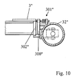
- the figure 10 appended drawings represents a second means of compensation of the irregularities of the ground which equips the front end of the intermediate frame 3 "and which is in the form of damping pivoting supports 300" of the rollers with horizontal axis of support to the ground 32 ", these 300 "damping pivoting supports each being provided with at least one damping device 301.
- Each damping device 301" consists of a pin guided in the damping pivoting support 300 "and in a stack of spring washers mounted on said damping device 301". pin and held thereon by means of a nut, the end of said pin close to the nut resting on a corresponding end cross member 302 "mounting damping pivoting supports 300" of the intermediate frame 3 ".
- the invention it is possible to provide a mobile vertical storage device that can be easily installed in premises that are not specifically assigned to a storage, so in premises that can be transformed inexpensively into storage rooms or still in a part of local still having other assignments.
- This vertical storage device is of relatively simple constitution and a cost significantly lower than the mobile device known to date and requiring heavy infrastructure.
Landscapes
- Engineering & Computer Science (AREA)
- Mechanical Engineering (AREA)
- Warehouses Or Storage Devices (AREA)
Claims (28)
- Bewegliche vertikale Vorrichtung zum Lagern, die im Wesentlichen aus einem horizontalen Rahmen (2) besteht, auf dem in regelmäßigen Abständen Träger (1) für horizontale Auflagen (1') zur Aufnahme und Lagerung von langen Gegenständen, wie z.B. Profilen angeordnet sind, wobei der Rahmen (2) beweglich ist und mit einem Mittel (3) zum Festlegen auf dem Boden und zum Verlagern entlang seiner Längsachse zusammenwirkt,
dadurch gekennzeichnet, dass
das Mittel (3) zum Festlegen auf dem Boden zum einen von einem Rahmen (3') für das Verankern in dem Boden und einem Zwischenrahmen (3") gebildet ist, der auf dem Rahmen (3') für das Verankern in dem Boden geführt ist und der eine Führung und eine Aufnahme für den beweglichen Rahmen (2) bildet, und zum anderen von einer Verlagerungseinheit (4) für den beweglichen Rahmen (2) und den Zwischenrahmen (3") gebildet ist. - Vorrichtung nach Anspruch 1, dadurch gekennzeichnet, dass der bewegliche Rahmen (2) und der Zwischenrahmen (3") sowie der Rahmen (3') für das Verankern in dem Boden teleskopartig ineinander montiert sind, wobei der Zwischenrahmen (3") einerseits auf dem Rahmen (3') für das Verankern in dem Boden geführt ist und andererseits als eine Führung für den beweglichen Rahmen (2) dient.
- Vorrichtung nach einem der Ansprüche 1 oder 2, dadurch gekennzeichnet, dass der Zwischenrahmen (3") an seinem Ende, das demjenigen Ende entgegengesetzt ist, das aus dem Rahmen (3) für das Verankern in dem Boden heraus nach außen bewegt werden kann, einen die Ausziehbewegung begrenzenden Endanschlag (5) aufweist, der mit einem Element (6) zusammenwirkt, das gegenüber dem Rahmen (3') für das Verankern in dem Boden einen Vorsprung bildet, wobei das einen Vorsprung bildende Element (6) an dem Rahmen (3') für das Verankern in dem Boden oder unmittelbar an dem Boden festgelegt ist.
- Vorrichtung nach einem der Ansprüche 1 bis 3, dadurch gekennzeichnet, dass der Rahmen (3') für das Verankern in dem Boden und der bewegliche Rahmen (2) als zwei übereinander liegende, zueinander versetzt angeordnete Winkelstücke ausgebildet sind, die jeweils mit Laufrollen (31' und 21) versehen sind, die sich an ihren vertikalen Flanken befinden und die sich auf in Längsrichtung erstreckten Profilträgern (31") abstützen, die an den entsprechenden Rändern des Zwischenrahmens (3") vorgesehen sind, wobei die Laufrollen (31' und 21) unter letzterem kombiniert eine radiale Lagerfläche aufweisende und seitlich führende Rollen sind, die sich auf beiden Seiten an den sich in Längsrichtung erstreckten Profilträgern (31") abstützen, so dass sich der bewegliche Rahmen (2) auf dem Zwischenrahmen (3") bewegen kann, ohne dass er auf dem Rahmen (3') für das Verankern in dem Boden schleift, so dass auf diese Weise eine Verlagerung der von dem Zwischenrahmen (3") und dem beweglichen Rahmen (2) gebildeten Einheit möglich ist.
- Vorrichtung nach einem der Ansprüche 1, 2 oder 4, dadurch gekennzeichnet, dass der bewegliche Rahmen (2) an seinem vorderen Ende mindestens ein auf dem Boden aufliegendes, schwenkbar gelagertes Paar Laufrollen (22) mit einer horizontalen Achse aufweist, das an mit einem eine vertikale Lagerachse aufweisenden Lager schwenkbeweglich auf den beweglichen Rahmen (2) montiert ist.
- Vorrichtung nach Anspruch 5, dadurch gekennzeichnet, dass der bewegliche Rahmen drei Paare von auf dem Boden (22) aufliegenden Laufrollen (22) mit einer horizontalen Achse aufweist, die über die gesamte Breite der Frontpartie des beweglichen Rahmens (2) gleichmäßig verteilt angeordnet sind.
- Vorrichtung nach einem der Ansprüche 1 bis 4, dadurch gekennzeichnet, dass der Zwischenrahmen (3") an seinem vorderen Ende mit zwei Paar auf dem Boden aufliegenden Laufrollen (32") mit einer horizontalen Achse versehen ist, die jeweils mit einem eine vertikale Lagerachse aufweisenden Lager an dem beweglichen Rahmen (3') schwenkbeweglich auf den beiden Seiten von dessen vorderem Ende montiert sind, wobei dieser in der Verlängerung der Profilträger (31") und wenigstens teilweise in der Achse der kombiniert eine radiale Lagerfläche aufweisenden und seitlich geführten Rollen (21) des beweglichen Rahmens (2) dargestellt wird.
- Vorrichtung nach einem der Ansprüche 4 oder 7, dadurch gekennzeichnet, dass die kombiniert eine radiale Lagerfläche aufweisenden und seitlich geführten Rollen (21) des beweglichen Rahmens (2) an den vertikalen Flanken der Winkelstücke, die den beweglichen Rahmen (2) bilden, über einen Abschnitt der Länge von letzteren, ausgehend von dem hinteren Ende des beweglichen Rahmens (2), welcher der Überlappungslänge des beweglichen Rahmens (2) mit dem Zwischenrahmen (3") entspricht, wenn der bewegliche Rahmen (2) gegenüber dem Rahmen (3') für das Verankern vollständig ausgezogen ist, vorgesehen sind.
- Vorrichtung nach Anspruch 1, dadurch gekennzeichnet, dass die Verlagerungseinheit (4) für den beweglichen Rahmen (2) und der Zwischenrahmen (3") von einem an den beweglichen Rahmen (2) angeschlossenen Teil (4') und einem Teil (4") gebildet ist, das mit dem an den beweglichen Rahmen (2) angeschlossenen Teil (4') zusammenwirkt und das an einem Halter (7) festgelegt ist, der mit dem Ende des Rahmens (3') für das Verankern in dem Boden verbunden sein kann, das der Öffnung für das Ausziehen des beweglichen Rahmens (2) gegenüberliegend angeordnet ist.
- Vorrichtung nach Anspruch 9, dadurch gekennzeichnet, dass der Teil (4') der Verlagerungseinheit, die mit dem beweglichen Rahmen (2) einstückig ist, als eine Zahnstange ausgebildet ist, und der Teil (4") von einer Getriebeeinheit (41) gebildet ist, der auf dem Halter (7) an dem Ende des Rahmens (3') für das Verankern in dem Boden festgelegt ist, der ein Antriebsritzel (42), das an dem gegenüberliegenden Ende des Rahmens (3') für das Verankern in dem Boden angeordnet ist, mit Hilfe einer Kette (43) und Kettenrädern (44) antreibt.
- Vorrichtung nach einem der Ansprüche 1 bis 10, dadurch gekennzeichnet, dass der bewegliche Rahmen (2) an seinem hinteren, der Ausziehöffnung des Rahmens (3') für das Verankern in dem Boden gegenüberliegenden Ende einen Anschlag (8) für das Einziehen und Ausziehen aufweist, der jeweils mit Endkontakten für das Ausziehen (9) und Einziehen (10) zusammenwirkt, die auf dem Rahmen (3') für das Verankern in dem Boden vorgesehen sind, wobei die Endkontakte in den Endstellungen des beweglichen Rahmens (2) das automatische Abschalten der Getriebeeinheit (41) der Verlagerungseinheit (4) für das Verlagern des Zwischenrahmens (3") und des beweglichen Rahmens (2) bewirken.
- Vorrichtung nach einem der Ansprüche 1, 9 oder 10, dadurch gekennzeichnet, dass die Verlagerungseinheit (4) für das Verlagern des Zwischenrahmens (3") und des beweglichen Rahmens (2) mittels eines Schaltschranks einer bekannten Bauart gesteuert ist, der mindestens einen Ein-/Aus-Schalter und einen Sicherheitsschalter aufweist, wobei der Schaltschrank außerdem mit den Endkontakten für das Ausziehen (9) und das Einziehen (10) verbunden ist und eine Sicherheitseinrichtung (11) für das automatische Anhalten am Ende des beweglichen Rahmens (2) vorgesehen ist, der sich aus dem Zwischenrahmen (3") und dem in dem Boden verankerten Rahmen (3') heraus bewegt, wobei die Sicherheitseinrichtung z. B. als eine bewegliche, mit einem Schalter versehene Platte ausgebildet ist.
- Vorrichtung nach einem der Ansprüche 1 bis 12, dadurch gekennzeichnet, dass der bewegliche Rahmen (2) an seinem hinteren Ende, damit dieses Ende in dem Zwischenrahmen (3") geführt bleibt, ein Antriebselement (12) aufweist, das geringfügig unter dem vorstehenden Ende des beweglichen Rahmens (2) hervorsteht und das mit einem Querträger (300") des Zwischenrahmens (3") zusammenwirkt.
- Vorrichtung nach einem der Ansprüche 1 bis 12, dadurch gekennzeichnet, dass der Rahmen (3') für das Verankern in dem Boden mittels ebener Querbalken versteift ist, die gleichzeitig für das Verankern in dem Boden mittels Ringschrauben oder dergleichen dienen, wobei der hintere Querbalken, der die Schienen verbindet, die die Seiten des Rahmens (3') bilden, gleichzeitig als Halter für das einen Vorsprung bildende Element (6) dient, das für das Zusammenwirken mit dem Anschlag (5) für das Ausziehen des Zwischenrahmens (3") dient.
- Vorrichtung nach einem der Ansprüche 1 bis 12, dadurch gekennzeichnet, dass der Zwischenrahmen (3") in Querrichtung durch Verbindungsprofile verstärkt ist, die von dem Boden beabstandet verlaufen, um ein ausreichendes Verlagern des Zwischenrahmens (3") zu gewährleisten, ohne dass dabei die Gefahr einer Kollision mit einem Befestigungselement des Rahmens (3') für das Verankern oder mit dem einen Vorsprung bildenden Element (6) des Rahmens besteht, das für das Zusammenwirken mit dem Endanschlag (5) dient.
- Vorrichtung nach einem der Ansprüche 1 bis 13, dadurch gekennzeichnet, dass der bewegliche Rahmen (2) durch in die Längsrichtung erstreckte Schienen gebildet ist, welche die kombiniert eine radiale Lagerfläche aufweisenden und seitlich geführten Rollen (21) tragen, die mit den Längsprofilen (31") des Zwischenrahmens (3") zusammenwirken, wobei diese Schienen in Querrichtung mit Profilbalken (2") versteift sind, zwischen denen die Haltebasen der Träger (1) für die horizontalen Auflagen (1') zur Aufnahme und Lagerung von langen Gegenständen, wie z. B. Profilen montiert sind.
- Vorrichtung nach einem der Ansprüche 1 bis 12, dadurch gekennzeichnet, dass der Rahmen (3') für das Verankern in dem Boden (3) zum einen mit einem Mittel (431) für das Führen der Kette (43) sowie Einrichtungen für das Einstellen der Spannung von letzterer mittels Kettenrädern (44) versehen ist und zum anderen mit wenigstens einer faltbaren Schutzhülle für die elektrischen Leiter zum Anschließen der Endkontakte (9 und 10).
- Vorrichtung nach einem der Ansprüche 1 bis 17, dadurch gekennzeichnet, dass sie mit einem kuppelnden Antriebsmittel versehen ist.
- Vorrichtung nach Anspruch 18, dadurch gekennzeichnet, dass das kuppelnde Antriebsmittel als eine Klauenkupplung ausgebildet ist, bei der die Klauen fest auf der Antriebswelle der Getriebemotoreinheit montiert sind, die auf dem Halter an dem Ende des Rahmens für das Verankern in dem Boden festgelegt ist, wobei die Klauen lose und mit der Möglichkeit einer durch eine Steuergabel oder dergleichen bewirkten Schiebebewegung auf der Antriebswelle montiert sind und für eine jede jeweils ein Kettenrad für das Antreiben einer Kette zum Antreiben des Antriebsritzels vorgesehen ist, das sich an dem Ende befindet, das dem Rahmen für das Verankern in dem Boden gegenüberliegt.
- Vorrichtung nach Anspruch 1, dadurch gekennzeichnet, dass die Verlagerungseinheit (4) für den beweglichen Rahmen (2) und den Zwischenrahmen (3") als eine Getriebemotoreinheit ausgebildet ist, die auf den distalen Abschnitt des beweglichen Rahmens (2) montiert ist und die mindestens eine Rolle (21) für das Abstützen und Verlagern des beweglichen Rahmens (2) direkt antreibt.
- Vorrichtung nach Anspruch 20, dadurch gekennzeichnet, dass die Getriebemotoreinheit, welche die Verlagerungseinheit (4) für den beweglichen Rahmen (2) und den Zwischenrahmen (3") bildet, eine Rolle (21) für das Abstützen und Verlagern des beweglichen Rahmens (3") mittels seiner Antriebswelle (420) antreibt, die auf ein Paar Umlenkritzel (421) wirkt, die untereinander durch eine Kette (422) verbunden sind und die jeweils mit einem Antriebsritzel (423), das an die Antriebswelle (420) angeschlossen ist, und mit einem Getriebezahnrad kämmen, das mit der Rolle (21) für das Abstützen und Verlagern zusammenwirkt.
- Vorrichtung nach einem der Ansprüche 19 oder 20, dadurch gekennzeichnet, dass die elektrischen Leiter für das Anschließen der Endkontakte und das elektrische Verkabeln der Verlagerungseinheit (4) des beweglichen Rahmens (2) und des Zwischenrahmens (3") in einem Freiluftkabel zusammengefasst sind, das in regelmäßigen Abständen mit Ösen an einem Stahlseil gehalten wird, das mit seinem freien Ende an dem oberen Teil des Trägers (1) für horizontale Auflagen (1') an dem vorderen Ende des beweglichen Rahmens (2) angebracht ist, wobei dieses Stahlseil auf eine automatische Aufrollvorrichtung montiert ist, die sich auf einem Halter befindet, der an dem hinteren Ende des Rahmens (3') für das Verankern in dem Boden angeordnet ist.
- Vorrichtung nach Anspruch 1, dadurch gekennzeichnet, dass die Verlagerungseinheit (4) für den beweglichen Rahmen (2) und den Zwischenrahmen (3") von einem Teleskopzylinder gebildet ist, der sich mit seinem Zylinderabschnitt auf dem Halter (7) abstützt, der mit dem Ende des Rahmens (3') für das Verankern in dem Boden verbunden ist, das dem Ende mit der Öffnung für das Ausziehen des beweglichen Rahmens (2) gegenüberliegt, und mit dem Ende seiner äußeren Schubstange auf dem distalen Querbalken des beweglichen Rahmens (2), wobei er entsprechende Durchgänge des Zwischenrahmens (3") und des beweglichen Rahmens (2) durchgreift.
- Vorrichtung nach einem der Ansprüche 1 bis 23, dadurch gekennzeichnet, dass sie ausserdem mit Mittel zum Ausgleichen von Unebenheiten des Bodens versehen ist.
- Vorrichtung nach Anspruch 24, dadurch gekennzeichnet, dass der bewegliche Rahmen (2) an seinem vorderen Ende eine erste Einrichtung zum Ausgleichen von Unebenheiten des Bodens in Form eines Querbalkens (200) zur Aufnahme der Lager der Laufrollen (22) für das Abstützen auf dem Boden und/oder der Laufrollen (21) für das Abstützen und das Verlagern aufweist, wobei der Querbalken (200) an seinen Enden mit den Längsträgern (201) des beweglichen Rahmens (2) über eine Führung mit einem Linear-Kugellager (202) und eine Dämpfungsvorrichtung (203) beweglich verbunden ist.
- Vorrichtung nach Anspruch 25, dadurch gekennzeichnet, dass die Dämpfungsvorrichtung (203) aus Zapfen besteht, die an den Längsträgern befestigt sind und die die Enden des Querbalkens (200) durchgreifen, wobei auf die Zapfen Tellerfederstapel montiert sind, die auf letzteren mittels Muttern gehalten werden und die sich auf dem oberen Teil des Querbalkens abstützen, um ausgehend von diesem auf die Längsträger (201) eine Anpresskraft auszuüben.
- Vorrichtung nach Anspruch 24, dadurch gekennzeichnet, dass der Zwischenrahmen (3") an seinem vorderen Ende eine zweite Einrichtung zum Kompensieren von Unebenheiten des Bodens aufweist, die als schwenkbare stoßgedämpfte Lagerböcke (300") für die Laufrollen mit horizontaler Achse zum Abstützen auf dem Boden (32") ausgebildet sind, wobei die schwenkbaren stoßgedämpften Lagerböcke (300") jeweils mit mindestens einer Dämpfungsvorrichtung (301") versehen sind.
- Vorrichtung nach Anspruch 27, dadurch gekennzeichnet, dass jede Dämpfungsvorrichtung (301 ") aus einem in dem schwenkbaren stoßgedämpften Lagerbock (300") geführten Zapfen und aus einem Stapel Tellerfedern besteht, die auf den Zapfen montiert sind und auf diesen mit einer Mutter gehalten werden, wobei das Ende des Zapfens bei der Mutter auf einen entsprechenden End-Montageträger (302") für das Halten der schwenkbaren stoßgedämpften Lagerböcke (300") des Zwischenrahmens (3") drückt.
Applications Claiming Priority (1)
| Application Number | Priority Date | Filing Date | Title |
|---|---|---|---|
| FR0651466A FR2900397B1 (fr) | 2006-04-26 | 2006-04-26 | Dispositif de stockage vertical mobile |
Publications (2)
| Publication Number | Publication Date |
|---|---|
| EP1849720A1 EP1849720A1 (de) | 2007-10-31 |
| EP1849720B1 true EP1849720B1 (de) | 2014-07-09 |
Family
ID=37421035
Family Applications (1)
| Application Number | Title | Priority Date | Filing Date |
|---|---|---|---|
| EP07300975.5A Not-in-force EP1849720B1 (de) | 2006-04-26 | 2007-04-24 | Mobile vertikale Speichervorrichtung |
Country Status (2)
| Country | Link |
|---|---|
| EP (1) | EP1849720B1 (de) |
| FR (1) | FR2900397B1 (de) |
Families Citing this family (2)
| Publication number | Priority date | Publication date | Assignee | Title |
|---|---|---|---|---|
| CN111573093B (zh) * | 2020-04-10 | 2021-08-20 | 涡阳县康仕达机电有限公司 | 一种车桥成品转运装置 |
| CN118025970B (zh) * | 2024-03-18 | 2024-09-10 | 中建八局第二建设有限公司 | 一种用于墙板码垛的吊装机 |
Citations (1)
| Publication number | Priority date | Publication date | Assignee | Title |
|---|---|---|---|---|
| US3445010A (en) * | 1967-07-10 | 1969-05-20 | Triax Co | Automatic warehousing system for bar storage |
Family Cites Families (5)
| Publication number | Priority date | Publication date | Assignee | Title |
|---|---|---|---|---|
| US3563180A (en) * | 1969-01-24 | 1971-02-16 | Olin Corp | Movable storage rack |
| GB1371193A (en) * | 1972-02-03 | 1974-10-23 | Taylor Ltd John H | Storage racks |
| DE3524141A1 (de) * | 1985-07-05 | 1987-01-15 | Heinrich Sauer Gmbh & Co Kg | Regal zur lagerung von stangenmaterial |
| DE4142355B4 (de) * | 1991-12-20 | 2009-01-08 | Advanced Technik Gmbh | Verfahrbare Krananlage |
| US5938047A (en) * | 1998-03-27 | 1999-08-17 | Ellis; Chris | Material storage and retrieval assembly |
-
2006
- 2006-04-26 FR FR0651466A patent/FR2900397B1/fr not_active Expired - Fee Related
-
2007
- 2007-04-24 EP EP07300975.5A patent/EP1849720B1/de not_active Not-in-force
Patent Citations (1)
| Publication number | Priority date | Publication date | Assignee | Title |
|---|---|---|---|---|
| US3445010A (en) * | 1967-07-10 | 1969-05-20 | Triax Co | Automatic warehousing system for bar storage |
Also Published As
| Publication number | Publication date |
|---|---|
| FR2900397A1 (fr) | 2007-11-02 |
| FR2900397B1 (fr) | 2008-07-18 |
| EP1849720A1 (de) | 2007-10-31 |
Similar Documents
| Publication | Publication Date | Title |
|---|---|---|
| EP3456601B1 (de) | Fördersystem eines länglichen bauelements, förderfahrzeug, das mit einem solchen system ausgestattet ist | |
| FR2774083A1 (fr) | Dispositif elevateur perfectionne | |
| EP0755841A1 (de) | Lastförderwagen | |
| EP0701963B2 (de) | Motorhubwagen mit teleskopischem Arm | |
| CA2670672A1 (fr) | Sabot de calage d'une roue et installation de calage motorisee | |
| EP1849720B1 (de) | Mobile vertikale Speichervorrichtung | |
| EP0905083A1 (de) | Wagen mit Hubmast, geeignet zur Montage an das Ende eines Transportfahrzeugs | |
| FR2667837A1 (fr) | Convoyeur du type tramway monorail. | |
| EP3949925B1 (de) | Abnehmbares elektrisches antriebssystem für ein rollendes objekt, gleichzeitiges und kombiniertes greifen und entfernen der räder in längsrichtung | |
| EP1243463A1 (de) | Fahrzeug mit einer Vorrichtung zum Handhaben von einem Container und Verfahren für das Heben einer Last mit einem solchen Fahrzeug | |
| WO1990012707A1 (fr) | Appareil de manutention automatique de charges allongees sur le toit d'un vehicule | |
| EP0757132B1 (de) | Brückenteil, insbesondere zur Überwindung von Gräben durch Fahrzeuge und System zum transportieren und ablegen von solchen Brückenteilen | |
| EP0773153B1 (de) | Bewegliche Plattform für die Überwachung von Höhenunterschieden | |
| EP0185826B1 (de) | Hebevorrichtung für Lader an Landwirtschaftstraktoren | |
| FR3125807A1 (fr) | Dispositif de déplacement-basculement d’une pile d’objets | |
| FR2490166A1 (fr) | Vehicule equipe de dispositifs de transbordement lateral de conteneurs | |
| EP0374194B1 (de) | Antriebssystem und anwendungsverfahren für auf einer schiene bewegbare wagen | |
| EP0700862A1 (de) | Hebebühne zum Anheben eines Fahrzeug mittels seines Chassis oder seiner Räder | |
| CH650045A5 (fr) | Machine de chantier ferroviaire pour la saisie et le portage de troncons et/ou d'appareils de voie montes. | |
| EP1361110A1 (de) | Gütertransportfahrzeug mit einer Hubplattform | |
| EP0809600A2 (de) | Lastaufnahme-fahrzeug | |
| FR3139519A1 (fr) | Dispositif d’arrimage de charges, notamment de balles de fourrage, sur un véhicule de transport de charges, et véhicule de transport de charges comprenant au moins un tel dispositif d’arrimage | |
| FR2980995A1 (fr) | Dispositif de manutention a mat vertical telescopique | |
| FR3101053A1 (fr) | Chariot élévateur | |
| FR2735763A1 (fr) | Chariot elevateur, en particulier du type a fourches laterales |
Legal Events
| Date | Code | Title | Description |
|---|---|---|---|
| PUAI | Public reference made under article 153(3) epc to a published international application that has entered the european phase |
Free format text: ORIGINAL CODE: 0009012 |
|
| AK | Designated contracting states |
Kind code of ref document: A1 Designated state(s): AT BE BG CH CY CZ DE DK EE ES FI FR GB GR HU IE IS IT LI LT LU LV MC MT NL PL PT RO SE SI SK TR |
|
| AX | Request for extension of the european patent |
Extension state: AL BA HR MK YU |
|
| 17P | Request for examination filed |
Effective date: 20071207 |
|
| 17Q | First examination report despatched |
Effective date: 20080111 |
|
| AKX | Designation fees paid |
Designated state(s): AT BE BG CH CY CZ DE DK EE ES FI FR GB GR HU IE IS IT LI LT LU LV MC MT NL PL PT RO SE SI SK TR |
|
| GRAP | Despatch of communication of intention to grant a patent |
Free format text: ORIGINAL CODE: EPIDOSNIGR1 |
|
| INTG | Intention to grant announced |
Effective date: 20140123 |
|
| RIN1 | Information on inventor provided before grant (corrected) |
Inventor name: HUBER, PASCAL |
|
| GRAS | Grant fee paid |
Free format text: ORIGINAL CODE: EPIDOSNIGR3 |
|
| GRAA | (expected) grant |
Free format text: ORIGINAL CODE: 0009210 |
|
| AK | Designated contracting states |
Kind code of ref document: B1 Designated state(s): AT BE BG CH CY CZ DE DK EE ES FI FR GB GR HU IE IS IT LI LT LU LV MC MT NL PL PT RO SE SI SK TR |
|
| REG | Reference to a national code |
Ref country code: GB Ref legal event code: FG4D Free format text: NOT ENGLISH |
|
| REG | Reference to a national code |
Ref country code: AT Ref legal event code: REF Ref document number: 676496 Country of ref document: AT Kind code of ref document: T Effective date: 20140715 Ref country code: CH Ref legal event code: EP |
|
| REG | Reference to a national code |
Ref country code: IE Ref legal event code: FG4D Free format text: LANGUAGE OF EP DOCUMENT: FRENCH |
|
| REG | Reference to a national code |
Ref country code: DE Ref legal event code: R096 Ref document number: 602007037535 Country of ref document: DE Effective date: 20140814 |
|
| REG | Reference to a national code |
Ref country code: CH Ref legal event code: NV Representative=s name: RENTSCH PARTNER AG, CH |
|
| REG | Reference to a national code |
Ref country code: AT Ref legal event code: MK05 Ref document number: 676496 Country of ref document: AT Kind code of ref document: T Effective date: 20140709 |
|
| REG | Reference to a national code |
Ref country code: NL Ref legal event code: VDEP Effective date: 20140709 |
|
| REG | Reference to a national code |
Ref country code: LT Ref legal event code: MG4D |
|
| PG25 | Lapsed in a contracting state [announced via postgrant information from national office to epo] |
Ref country code: SE Free format text: LAPSE BECAUSE OF FAILURE TO SUBMIT A TRANSLATION OF THE DESCRIPTION OR TO PAY THE FEE WITHIN THE PRESCRIBED TIME-LIMIT Effective date: 20140709 Ref country code: ES Free format text: LAPSE BECAUSE OF FAILURE TO SUBMIT A TRANSLATION OF THE DESCRIPTION OR TO PAY THE FEE WITHIN THE PRESCRIBED TIME-LIMIT Effective date: 20140709 Ref country code: BG Free format text: LAPSE BECAUSE OF FAILURE TO SUBMIT A TRANSLATION OF THE DESCRIPTION OR TO PAY THE FEE WITHIN THE PRESCRIBED TIME-LIMIT Effective date: 20141009 Ref country code: PT Free format text: LAPSE BECAUSE OF FAILURE TO SUBMIT A TRANSLATION OF THE DESCRIPTION OR TO PAY THE FEE WITHIN THE PRESCRIBED TIME-LIMIT Effective date: 20141110 Ref country code: GR Free format text: LAPSE BECAUSE OF FAILURE TO SUBMIT A TRANSLATION OF THE DESCRIPTION OR TO PAY THE FEE WITHIN THE PRESCRIBED TIME-LIMIT Effective date: 20141010 Ref country code: FI Free format text: LAPSE BECAUSE OF FAILURE TO SUBMIT A TRANSLATION OF THE DESCRIPTION OR TO PAY THE FEE WITHIN THE PRESCRIBED TIME-LIMIT Effective date: 20140709 Ref country code: LT Free format text: LAPSE BECAUSE OF FAILURE TO SUBMIT A TRANSLATION OF THE DESCRIPTION OR TO PAY THE FEE WITHIN THE PRESCRIBED TIME-LIMIT Effective date: 20140709 |
|
| PG25 | Lapsed in a contracting state [announced via postgrant information from national office to epo] |
Ref country code: LV Free format text: LAPSE BECAUSE OF FAILURE TO SUBMIT A TRANSLATION OF THE DESCRIPTION OR TO PAY THE FEE WITHIN THE PRESCRIBED TIME-LIMIT Effective date: 20140709 Ref country code: IS Free format text: LAPSE BECAUSE OF FAILURE TO SUBMIT A TRANSLATION OF THE DESCRIPTION OR TO PAY THE FEE WITHIN THE PRESCRIBED TIME-LIMIT Effective date: 20141109 Ref country code: CY Free format text: LAPSE BECAUSE OF FAILURE TO SUBMIT A TRANSLATION OF THE DESCRIPTION OR TO PAY THE FEE WITHIN THE PRESCRIBED TIME-LIMIT Effective date: 20140709 Ref country code: NL Free format text: LAPSE BECAUSE OF FAILURE TO SUBMIT A TRANSLATION OF THE DESCRIPTION OR TO PAY THE FEE WITHIN THE PRESCRIBED TIME-LIMIT Effective date: 20140709 Ref country code: AT Free format text: LAPSE BECAUSE OF FAILURE TO SUBMIT A TRANSLATION OF THE DESCRIPTION OR TO PAY THE FEE WITHIN THE PRESCRIBED TIME-LIMIT Effective date: 20140709 Ref country code: PL Free format text: LAPSE BECAUSE OF FAILURE TO SUBMIT A TRANSLATION OF THE DESCRIPTION OR TO PAY THE FEE WITHIN THE PRESCRIBED TIME-LIMIT Effective date: 20140709 |
|
| REG | Reference to a national code |
Ref country code: DE Ref legal event code: R097 Ref document number: 602007037535 Country of ref document: DE |
|
| REG | Reference to a national code |
Ref country code: FR Ref legal event code: PLFP Year of fee payment: 9 |
|
| PG25 | Lapsed in a contracting state [announced via postgrant information from national office to epo] |
Ref country code: CZ Free format text: LAPSE BECAUSE OF FAILURE TO SUBMIT A TRANSLATION OF THE DESCRIPTION OR TO PAY THE FEE WITHIN THE PRESCRIBED TIME-LIMIT Effective date: 20140709 Ref country code: IT Free format text: LAPSE BECAUSE OF FAILURE TO SUBMIT A TRANSLATION OF THE DESCRIPTION OR TO PAY THE FEE WITHIN THE PRESCRIBED TIME-LIMIT Effective date: 20140709 Ref country code: DK Free format text: LAPSE BECAUSE OF FAILURE TO SUBMIT A TRANSLATION OF THE DESCRIPTION OR TO PAY THE FEE WITHIN THE PRESCRIBED TIME-LIMIT Effective date: 20140709 Ref country code: RO Free format text: LAPSE BECAUSE OF FAILURE TO SUBMIT A TRANSLATION OF THE DESCRIPTION OR TO PAY THE FEE WITHIN THE PRESCRIBED TIME-LIMIT Effective date: 20140709 Ref country code: EE Free format text: LAPSE BECAUSE OF FAILURE TO SUBMIT A TRANSLATION OF THE DESCRIPTION OR TO PAY THE FEE WITHIN THE PRESCRIBED TIME-LIMIT Effective date: 20140709 Ref country code: SK Free format text: LAPSE BECAUSE OF FAILURE TO SUBMIT A TRANSLATION OF THE DESCRIPTION OR TO PAY THE FEE WITHIN THE PRESCRIBED TIME-LIMIT Effective date: 20140709 |
|
| PLBE | No opposition filed within time limit |
Free format text: ORIGINAL CODE: 0009261 |
|
| STAA | Information on the status of an ep patent application or granted ep patent |
Free format text: STATUS: NO OPPOSITION FILED WITHIN TIME LIMIT |
|
| 26N | No opposition filed |
Effective date: 20150410 |
|
| PGFP | Annual fee paid to national office [announced via postgrant information from national office to epo] |
Ref country code: DE Payment date: 20150523 Year of fee payment: 9 |
|
| PGFP | Annual fee paid to national office [announced via postgrant information from national office to epo] |
Ref country code: FR Payment date: 20150429 Year of fee payment: 9 |
|
| PG25 | Lapsed in a contracting state [announced via postgrant information from national office to epo] |
Ref country code: MC Free format text: LAPSE BECAUSE OF FAILURE TO SUBMIT A TRANSLATION OF THE DESCRIPTION OR TO PAY THE FEE WITHIN THE PRESCRIBED TIME-LIMIT Effective date: 20140709 Ref country code: LU Free format text: LAPSE BECAUSE OF FAILURE TO SUBMIT A TRANSLATION OF THE DESCRIPTION OR TO PAY THE FEE WITHIN THE PRESCRIBED TIME-LIMIT Effective date: 20150424 Ref country code: SI Free format text: LAPSE BECAUSE OF FAILURE TO SUBMIT A TRANSLATION OF THE DESCRIPTION OR TO PAY THE FEE WITHIN THE PRESCRIBED TIME-LIMIT Effective date: 20140709 |
|
| REG | Reference to a national code |
Ref country code: CH Ref legal event code: PL |
|
| GBPC | Gb: european patent ceased through non-payment of renewal fee |
Effective date: 20150424 |
|
| REG | Reference to a national code |
Ref country code: IE Ref legal event code: MM4A |
|
| PG25 | Lapsed in a contracting state [announced via postgrant information from national office to epo] |
Ref country code: GB Free format text: LAPSE BECAUSE OF NON-PAYMENT OF DUE FEES Effective date: 20150424 Ref country code: CH Free format text: LAPSE BECAUSE OF NON-PAYMENT OF DUE FEES Effective date: 20150430 Ref country code: LI Free format text: LAPSE BECAUSE OF NON-PAYMENT OF DUE FEES Effective date: 20150430 |
|
| PG25 | Lapsed in a contracting state [announced via postgrant information from national office to epo] |
Ref country code: IE Free format text: LAPSE BECAUSE OF NON-PAYMENT OF DUE FEES Effective date: 20150424 |
|
| REG | Reference to a national code |
Ref country code: DE Ref legal event code: R119 Ref document number: 602007037535 Country of ref document: DE |
|
| PG25 | Lapsed in a contracting state [announced via postgrant information from national office to epo] |
Ref country code: MT Free format text: LAPSE BECAUSE OF FAILURE TO SUBMIT A TRANSLATION OF THE DESCRIPTION OR TO PAY THE FEE WITHIN THE PRESCRIBED TIME-LIMIT Effective date: 20140709 |
|
| REG | Reference to a national code |
Ref country code: FR Ref legal event code: ST Effective date: 20161230 |
|
| PG25 | Lapsed in a contracting state [announced via postgrant information from national office to epo] |
Ref country code: FR Free format text: LAPSE BECAUSE OF NON-PAYMENT OF DUE FEES Effective date: 20160502 Ref country code: DE Free format text: LAPSE BECAUSE OF NON-PAYMENT OF DUE FEES Effective date: 20161101 |
|
| PG25 | Lapsed in a contracting state [announced via postgrant information from national office to epo] |
Ref country code: HU Free format text: LAPSE BECAUSE OF FAILURE TO SUBMIT A TRANSLATION OF THE DESCRIPTION OR TO PAY THE FEE WITHIN THE PRESCRIBED TIME-LIMIT; INVALID AB INITIO Effective date: 20070424 |
|
| PG25 | Lapsed in a contracting state [announced via postgrant information from national office to epo] |
Ref country code: BE Free format text: LAPSE BECAUSE OF NON-PAYMENT OF DUE FEES Effective date: 20150430 |
|
| PG25 | Lapsed in a contracting state [announced via postgrant information from national office to epo] |
Ref country code: TR Free format text: LAPSE BECAUSE OF FAILURE TO SUBMIT A TRANSLATION OF THE DESCRIPTION OR TO PAY THE FEE WITHIN THE PRESCRIBED TIME-LIMIT Effective date: 20140709 |