EP1849959B1 - Dampfturbine und Turbinenrotor - Google Patents
Dampfturbine und Turbinenrotor Download PDFInfo
- Publication number
- EP1849959B1 EP1849959B1 EP07008143A EP07008143A EP1849959B1 EP 1849959 B1 EP1849959 B1 EP 1849959B1 EP 07008143 A EP07008143 A EP 07008143A EP 07008143 A EP07008143 A EP 07008143A EP 1849959 B1 EP1849959 B1 EP 1849959B1
- Authority
- EP
- European Patent Office
- Prior art keywords
- turbine rotor
- temperature
- steam
- constituent part
- rotor constituent
- Prior art date
- Legal status (The legal status is an assumption and is not a legal conclusion. Google has not performed a legal analysis and makes no representation as to the accuracy of the status listed.)
- Not-in-force
Links
- 239000000470 constituent Substances 0.000 claims description 124
- 238000001816 cooling Methods 0.000 claims description 90
- 229910000831 Steel Inorganic materials 0.000 claims description 15
- 239000010959 steel Substances 0.000 claims description 15
- 238000003466 welding Methods 0.000 claims description 13
- 239000000463 material Substances 0.000 claims description 12
- 230000007797 corrosion Effects 0.000 claims description 10
- 238000005260 corrosion Methods 0.000 claims description 10
- 239000003779 heat-resistant material Substances 0.000 claims description 9
- 239000000956 alloy Substances 0.000 claims description 4
- 229910045601 alloy Inorganic materials 0.000 claims description 4
- 230000002093 peripheral effect Effects 0.000 claims description 3
- 238000011144 upstream manufacturing Methods 0.000 claims description 3
- 235000019628 coolness Nutrition 0.000 claims 1
- 238000010793 Steam injection (oil industry) Methods 0.000 description 15
- 238000010248 power generation Methods 0.000 description 7
- 210000003027 ear inner Anatomy 0.000 description 6
- 210000004907 gland Anatomy 0.000 description 5
- 238000007789 sealing Methods 0.000 description 5
- 230000008646 thermal stress Effects 0.000 description 4
- 238000000034 method Methods 0.000 description 3
- 230000007613 environmental effect Effects 0.000 description 2
- 238000005507 spraying Methods 0.000 description 2
- 230000008878 coupling Effects 0.000 description 1
- 238000010168 coupling process Methods 0.000 description 1
- 238000005859 coupling reaction Methods 0.000 description 1
- 230000006866 deterioration Effects 0.000 description 1
- 230000000694 effects Effects 0.000 description 1
- 238000004519 manufacturing process Methods 0.000 description 1
- 239000000203 mixture Substances 0.000 description 1
- 230000003647 oxidation Effects 0.000 description 1
- 238000007254 oxidation reaction Methods 0.000 description 1
- 238000003303 reheating Methods 0.000 description 1
Images


Classifications
-
- F—MECHANICAL ENGINEERING; LIGHTING; HEATING; WEAPONS; BLASTING
- F01—MACHINES OR ENGINES IN GENERAL; ENGINE PLANTS IN GENERAL; STEAM ENGINES
- F01D—NON-POSITIVE DISPLACEMENT MACHINES OR ENGINES, e.g. STEAM TURBINES
- F01D5/00—Blades; Blade-carrying members; Heating, heat-insulating, cooling or antivibration means on the blades or the members
- F01D5/02—Blade-carrying members, e.g. rotors
- F01D5/06—Rotors for more than one axial stage, e.g. of drum or multiple disc type; Details thereof, e.g. shafts, shaft connections
- F01D5/063—Welded rotors
-
- F—MECHANICAL ENGINEERING; LIGHTING; HEATING; WEAPONS; BLASTING
- F01—MACHINES OR ENGINES IN GENERAL; ENGINE PLANTS IN GENERAL; STEAM ENGINES
- F01D—NON-POSITIVE DISPLACEMENT MACHINES OR ENGINES, e.g. STEAM TURBINES
- F01D5/00—Blades; Blade-carrying members; Heating, heat-insulating, cooling or antivibration means on the blades or the members
- F01D5/02—Blade-carrying members, e.g. rotors
- F01D5/06—Rotors for more than one axial stage, e.g. of drum or multiple disc type; Details thereof, e.g. shafts, shaft connections
- F01D5/066—Connecting means for joining rotor-discs or rotor-elements together, e.g. by a central bolt, by clamps
-
- F—MECHANICAL ENGINEERING; LIGHTING; HEATING; WEAPONS; BLASTING
- F05—INDEXING SCHEMES RELATING TO ENGINES OR PUMPS IN VARIOUS SUBCLASSES OF CLASSES F01-F04
- F05C—INDEXING SCHEME RELATING TO MATERIALS, MATERIAL PROPERTIES OR MATERIAL CHARACTERISTICS FOR MACHINES, ENGINES OR PUMPS OTHER THAN NON-POSITIVE-DISPLACEMENT MACHINES OR ENGINES
- F05C2201/00—Metals
- F05C2201/04—Heavy metals
- F05C2201/0433—Iron group; Ferrous alloys, e.g. steel
- F05C2201/0466—Nickel
-
- F—MECHANICAL ENGINEERING; LIGHTING; HEATING; WEAPONS; BLASTING
- F05—INDEXING SCHEMES RELATING TO ENGINES OR PUMPS IN VARIOUS SUBCLASSES OF CLASSES F01-F04
- F05D—INDEXING SCHEME FOR ASPECTS RELATING TO NON-POSITIVE-DISPLACEMENT MACHINES OR ENGINES, GAS-TURBINES OR JET-PROPULSION PLANTS
- F05D2220/00—Application
- F05D2220/30—Application in turbines
- F05D2220/31—Application in turbines in steam turbines
-
- F—MECHANICAL ENGINEERING; LIGHTING; HEATING; WEAPONS; BLASTING
- F05—INDEXING SCHEMES RELATING TO ENGINES OR PUMPS IN VARIOUS SUBCLASSES OF CLASSES F01-F04
- F05D—INDEXING SCHEME FOR ASPECTS RELATING TO NON-POSITIVE-DISPLACEMENT MACHINES OR ENGINES, GAS-TURBINES OR JET-PROPULSION PLANTS
- F05D2300/00—Materials; Properties thereof
- F05D2300/10—Metals, alloys or intermetallic compounds
- F05D2300/17—Alloys
- F05D2300/171—Steel alloys
Definitions
- the present invention relates to a steam turbine and a turbine rotor, more particularly, to a steam turbine and a turbine rotor allowing the use of high-temperature steam at 620°C or higher.
- a steam turbine of such a conventional thermal power generation facility is generally under a steam temperature condition on order of not higher than 600°C, and therefore, its major components such as a turbine rotor and moving blades are made of ferritic heat resistant steel.
- JP-A 7-247806 (KOKAI), JP-A2000-282808 (KOKAI), and Japanese Patent No. 3095745 describe arts to construct a steam turbine power generation facility with the minimum use of an austenitic material for a steam turbine utilizing high-temperature steam at 650°C or higher.
- a superhigh-pressure turbine, a high-pressure turbine, an intermediate-pressure turbine, a low-pressure turbine, a second low-pressure turbine, and a generator are uniaxially connected, and the super high-pressure turbine and the high-pressure turbine are assembled in the same outer casing and thus are independent from the others.
- JP-A 2004-353603 (KOKAI) describes an art to cool turbine components by cooling steam in order to cope with the aforesaid increase in the steam temperature.
- EP 1 378 629 A1 discloses a turbine rotor composed of a plurality of forged pieces disposed in series in an axial direction and fixedly connected to each other.
- EP 1 577 494 A1 and EP 1 536 102 A disclose further turbine rotors.
- US 5 257 905 A discloses a rotor coupling anti-windage apparatus.
- the present invention was made to solve the above problems, and its object is to provide a steam turbine and a turbine rotor which can be driven by high-temperature steam to have improved thermal efficiency and which are excellent in economic efficiency, by using a corrosion and heat resistant material limitedly for predetermined turbine components.
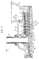
- FIG. 1 is a view showing a cross section of an upper casing part of a reheat steam turbine 100 of a first embodiment.
- the reheat steam turbine 100 includes a dual-structured casing composed of an inner casing 110 and an outer casing 111 provided outside the inner casing 110, and a heat chamber 112 is formed between the inner casing 110 and the outer casing 111.
- a turbine rotor 113 is penetratingly provided in the inner casing 110.
- nozzle diaphragm outer rings 117 are connected to an inner surface of the inner casing 110, and for example, nine-stages of nozzles 114 are provided.
- movingblades 115 are implanted in the turbine rotor 113 so as to correspond to these nozzles 114.
- This turbine rotor 113 is composed of: a high-temperature turbine rotor constituent part 113a positioned in an area extending from a nozzle 114a on a first stage (where steam temperature is 620°C or higher) to a moving blade 115a on a stage where the steam temperature becomes 550°C; and low-temperature turbine rotor constituent parts 113b connected to and sandwiching the high-temperature turbine rotor constituent part 113a.
- the high-temperature turbine rotor constituent part 113a and each of the low-temperature turbine rotor constituent parts 113b are connected by welding or bolting. The structure of a joint portion therebetween will be described later.
- the aforesaid inner casing 110 is composed of: a high-temperature casing constituent part110a covering the area where the high-temperature turbine rotor constituent part 113a is penetratingly provided; and low-temperature casing constituent parts 110b covering the areas where the low-temperature turbine rotor constituent parts 113b are penetratingly provided.
- the high-temperature casing constituent part 110a and each of the low-temperature casing constituent parts 110b are connected by welding or bolting, similarly to the aforesaid connection of the high-temperature turbine rotor constituent part 113a and each of the low-temperature turbine rotor constituent parts 113b.
- the high-temperature turbine rotor constituent part 113a and the high-temperature casing constituent part 110a positioned in the area extending from the nozzle 114a on the first stage to the moving blade 115a on the stage where the steam temperature becomes almost 550°C are exposed to high-temperature steam at 620°C or higher, which is an inlet steam temperature, and steam up to 550°C, and therefore are made of a corrosion and heat resistant material or the like whose mechanical strength (for example, a hundred thousand hour creep rupture strength) at high temperatures is high and which has steam oxidation resistance.
- the corrosion and heat resistant material for example, a Ni-based alloy is used, and concrete examples thereof are Inco625, Inco617, Inco713, and the like manufactured by Inco Limited.
- the nozzles 114, the nozzle diaphragm outer rings 117, nozzle diaphragm inner rings 118, the moving blades 115, and so on positioned in the area extending from the nozzle 114a on the first stage to the moving blade 115a on the stage where the steam temperature becomes 550°C are also made of the aforesaid corrosion and heat resistant material.
- the low-temperature turbine rotor constituent parts 113b and the low-temperature casing constituent parts 110b exposed to the steam at temperatures lower than 550°C are made of a material different from the aforesaid material forming the high-temperature turbine rotor constituent part 113a and the high-temperature casing constituent part 110a, and are preferably made of ferritic heat resistant steel or the like which has conventionally been in wide use as a material of a turbine rotor and a casing.
- this ferritic heat resistant steel are new 12Cr steel, modified 12Cr steel, 12Cr steel, 9Cr steel, CrMov Steel and the like but are not limited to these.
- nozzle labyrinths 119 are provided on turbine rotor 113 side surfaces of the nozzle diaphragm inner rings 118 to prevent leakage of the steam.
- the reheat steam turbine 100 further has a steam inlet pipe 130 which penetrates the outer casing 111 and the inner casing 110 and whose end portion communicates with and connected to a nozzle box 116 guiding the steam out to a moving blade side.
- These steam inlet pipe 130 and nozzle box 116 are exposed to the high-temperature steam at 620°C or hither which is the inlet steam temperature, and therefore are made of the aforesaid corrosion and heat resistant material.
- the nozzle box 116 may have a structure, for example, disclosed in JP-A No.
- a cooling steam channel in which cooling steam flows is formed in a wall of the nozzle box and shield plates are provided at intervals to cover parts of an inner surface of the wall of the nozzle box. This can reduce thermal stress and the like occurring in the wall of the nozzle box, so that high level of strength guarantee can be maintained.
- FIG. 2 is a view showing part of a cross section of a joint portion between the high-temperature turbine rotor constituent part 113a and the low-temperature turbine rotor constituent part 113b which are connected by welding.
- FIG. 3 to FIG. 5 are views each showing part of a cross section of a joint portion between the high-temperature turbine rotor constituent part 113a and the low-temperature turbine rotor constituent part 113b which are connected by bolting.
- the high-temperature turbine rotor constituent part 113a and the low-temperature turbine rotor constituent part 113b are connected by welding on a downstream side of the nozzle 114 positioned on an immediate downstream side of the moving blade 115a on the stage where the steam temperature becomes 550°C, whereby a joint portion 120 is formed.
- flange portions 121, 122 protruding outward in a radial direction of the turbine rotor 113 are formed in joint end portions of the high-temperature turbine rotor constituent part 113a and the low-temperature turbine rotor constituent part 113b respectively, and the both flange portions 121, 122 are bolt-connected with a bolt 123 and a nut 124.
- the joint portion 120 by the bolt-connection is positioned on an upstream side of the nozzle 114 positioned on an immediate downstream side of the moving blade 115a on the stage where the steam temperature becomes 550°C.
- the joint portion by the bolt connection may be disposed to face the nozzle labyrinth 119.
- the joint portion it is possible to shorten the whole length of the turbine rotor 113 compared with the case of the bolt connection shown in FIG. 3 .
- protruding portions 121a, 122a protruding to sides different from the joint surface where the high-temperature turbine rotor constituent part 113a and the low-temperature turbine rotor constituent part 113b are joined and preventing the exposure of the bolt 123 and the nut 124 in the radial direction of the turbine rotor 113 may be provided along outer peripheral edges of the flange portions 121, 122 of the high-temperature turbine rotor constituent part 113a and the low-temperature turbine rotor constituent part 113b respectively.
- the bolt 123 and the nut 124 do not protrude in the axial direction of the turbine rotor 113 but are housed in a recessed portion formed by the protruding portions 121a, 122a, the turbine rotor 113, and the flange portions 121, 122.
- the protruding portions 121a, 122a it is possible to prevent scattering of the bolt 123 and the nut 124.
- connection of the high-temperature turbine rotor constituent part 113a and the low-temperature turbine rotor constituent part 113b in a joint portion 126 formed at a position corresponding to the nozzle 114a on the first stage can be realized by the above-described welding or bolting. In this case, it is also possible to obtain the same operation and effect as are obtained by the above-described welding or bolting.
- the steam whose temperature is 620°C or higher flowing into the nozzle box 116 in the reheat steam turbine 100 via the steam inlet pipe 130 passes through the steam channel between the nozzles 114 fixed to the inner casing 110 and the moving blades 115 implanted in the turbine rotor 113 to rotate the turbine rotor 113. Further, most of the steam having finished expansion work passes through a discharge path 125 to be discharged out of the reheat steam turbine 100 and flows into a boiler through, for example, a low-temperature reheating pipe.
- the above-described reheat steam turbine 100 may include a structure to introduce, as cooling steam, part of the steam having finished the expansion work to an area between the inner casing 110 and the outer casing 111 to cool the outer casing 111 and the inner casing 110.
- the cooling steam is discharged through a gland sealing part 127a or the discharge path 125.
- a method of introducing the cooling steam is not limited to this, and for example, steam extracted from a stage in the middle of the reheat steam turbine 100 or steam extracted from another steam turbine may be used as the cooling steam.
- the Ni-based alloy which is a corrosion and heat resistant material is used only in the high-temperature parts, in the turbine rotor 113 and the inner casing 110, whose temperature exceeds a tolerable temperature of a conventional material (for example, ferritic heat resistant steel) determined by mechanical strength and corrosion resistance, so that they can be driven with high-temperature steam at 620°C or higher to be able to maintain performances such as predetermined thermal efficiency, and they are also highly cost efficient.
- a conventional material for example, ferritic heat resistant steel
- FIG. 6 is a view showing a cross section of an upper casing part of a reheat steam turbine 200 of a second embodiment.
- the reheat steam turbine 200 of the second embodiment includes cooling parts to introduce cooling steam, in addition to the structure of the reheat steam turbine 100 of the first embodiment.
- the structure and materials except those of the cooling parts are the same as those of the reheat steamturbine 100 of the first embodiment, and therefore, the same reference numerals and symbols are used to designate the same constituent elements as those of the reheat steam turbine 100 of the first embodiment and they will be described only briefly or will not be repeatedly described.
- the reheat steam turbine 200 includes: a cooling steam supply pipe 220 disposed along a turbine rotor 113 and injecting cooling steam 240 from the vicinity of a joint portion 126 at a position corresponding to a nozzle 114a on a first stage to a wheel part 210 corresponding to a moving blade 115 on a first stage; and a cooling steam supply pipe 230 disposed between a moving blade 115a on a stage where steam temperature becomes 550°C and a nozzle 114 positioned on an immediate downstream side of the moving blade 115a and injecting the cooling steam 240 to the turbine rotor 113.
- cooling steam supply pipes 220, 230 function as the cooling parts, and the cooling steam 240 injected from these cooling steam supply pipes 220, 230 cool the turbine rotor 113, joint portions 120, 126, further, an outer casing 111, an inner casing 110, and so on.
- cooling steam 240 usable is, for example, steam extracted from a high-pressure turbine, a boiler, or the like, steam extracted from a stage in the middle of the reheat steam turbine 200, or steam discharged to a discharge path 125 of the reheat steam turbine 200, and its supply source is appropriately selected based on a set temperature of the cooling steam 240.
- FIG. 7 is a view showing part of a cross section of the joint portion between the high-temperature turbine rotor constituent part 113a and the low-temperature turbine rotor constituent part 113b which are connected by welding, and also showing the cooling part.
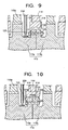
- FIG. 8 to FIG. 10 are views each showing part of a cross section of a joint portion between the high-temperature turbine rotor constituent part 113a and the low-temperature turbine rotor constituent part 113b which are connected by bolting, and also showing the cooling part.
- the high-temperature turbine rotor constituent part 113a and the low-temperature turbine rotor constituent part 113b are connected by welding on a downstream side of the nozzle 114 positioned on an immediate downstream side of the moving blade 115a on the stage where the steam temperature becomes 550°C, whereby the joint portion 120 is formed.
- the cooling steam supply pipe 230 is disposed between the moving blade 115a on the stage where the steam temperature becomes 550°C and the nozzle 114 positioned on the immediate downstream side of the moving blade 115a, and its steam injection port 230a is directed to the high-temperature turbine rotor constituent part 113a, being a predetermined distance apart from the high-temperature turbine rotor constituent part 113a.
- FIG. 8 Another possible structure is, as shown in FIG. 8 , that flange portions 121, 122 protruding outward in a radial direction of the turbine rotor 113 are formed in joint end portions of the high-temperature turbine rotor constituent part 113a and the low-temperature turbine rotor constituent part 113b respectively, and the both flange portions 121, 122 are bolt-connected with a bolt 123 and a nut 124.
- the cooling steam supply pipe 230 is disposed between the moving blade 115a on the stage where the steam temperature becomes 550°C and the flange portion 121 of the high-temperature turbine rotor constituent part 113a positioned on the immediate downstream side of the moving blade 115a, and its steam injection port 230a is directed to the high-temperature turbine rotor constituent part 113a, being a predetermined distance apart from the high-temperature turbine rotor constituent part 113a.
- the joint portion 120 by the bolt connection is positioned between the cooling steam supply pipe 230 and the nozzle 114 positioned on the downstream side of the moving blade 115a on the stage where the steam temperature becomes 550°C.
- FIG. 9 Another possible structure is, as shown in FIG. 9 , that the joint portion by the bolt connection is disposed to face a nozzle labyrinth 119, and the cooling steam supply pipe 230 is positioned between the moving blade 115a on the stage where the steam temperature becomes 550°C and the flange portion 121 of the high-temperature turbine rotor constituent part 113a positioned on an immediate downstream side of the moving blade 115a.
- the joint portion it is possible to shorten the whole length of the turbine rotor 13 compared with the case of the bolt connection shown in FIG. 8 .
- by supplying the cooling steam it is possible to prevent heat conduction to the low-temperature turbine rotor constituent part 113b side.
- protruding portions 121a, 122a protruding to a side different from the joint surface where the high-temperature turbine rotor constituent part 113a and the low-temperature turbine rotor constituent part 113b are joined and preventing the exposure of the bolt 123 and the nut 124 in the radial direction of the turbine rotor 113 may be provided along outer peripheral edges of the flange portions 121, 122 of the high-temperature turbine rotor constituent part 113a and the low-temperature turbine rotor constituent part 113b respectively.
- the bolt 12 and the nut 124 do not protrude in the axial direction of the turbine rotor 113 but are housed in a recessed portion formed by the protruding portions 121a, 122a, the turbine rotor 113, and the flange portions 121, 122.
- the protruding portions 121a, 122a it is possible to prevent scattering of the bolt 123 and the nut 124.
- the cooling steam supply pipe 220 is disposed along the turbine rotor 113, and its steam injection port 220a is positioned near the joint portion 126 at a position corresponding to the nozzle 114a on the first stage and is directed to the wheel part 210 corresponding to the moving blade 115 on the first stage. From this steam injection port 220a, the cooling steam 240 is injected toward the wheel part 210.
- the cooling steam 240 By thus supplying the cooling steam 240, it is possible to prevent heat conduction from the wheel part 210 corresponding to the moving blade 115a on the first stage where the high-temperature steam at 620°C or higher passes, to the low-temperature turbine rotor constituent part 113b side via the high-temperature turbine rotor constituent part 113a. Moreover, the cooling steam 240 also cools the joint portion 126 and its vicinity.
- the joint portion 126 at the position corresponding to the nozzle 114a on the first stage is formed by the weld connection as shown in FIG. 6 is described here, but the joint portion 126 may be formed by the bolt connection similarly to the above-described joint portion 120 on the downstream side.
- the cooling steam 240 is preferably supplied to an area between the joint portion 126 by the bolt connection and the wheel part 210 corresponding to the moving blade 115 on the first stage.
- the steam injection port 220a of the cooling steam supply pipe 220 is preferably directed to the wheel part 210 corresponding to the moving blade 115 on the first stage or the high-temperature turbine rotor constituent part 113a.
- the cooling steam 240 injected from the steam injection port 220a of the cooling steam supply pipe 220 collides with the wheel part 210 corresponding to the moving blade 115 on the first stage to cool the wheel part 210, and further comes into contact with the joint portion 126 to cool the joint portion 126 and its vicinity. Then, the cooling steam 240 passes through the gland sealing part 127b, and part thereof flows between the outer casing 111 and the inner casing 110 to cool the both casings. Further, the cooling steam 240 is introduced into a heat chamber 112 to be discharged through the discharge path 125. On the other hand, the rest of the cooling steam 240 having passed through the gland sealing part 127b passes through a gland sealing part 127a to be discharged.
- the cooling steam240 injected from the steam injection port 230a of the cooling steam supply pipe 230 collides with the high-temperature turbine rotor constituent part 113a on an immediate downstream side of the moving blade 115a on the stage where the steam temperature becomes 550°C and cools the high-temperature turbine rotor constituent part 113a. Subsequently, the cooling steam 240 flows downstream between the nozzle labyrinth 119 and the high-temperature turbine rotor constituent part 113a to cool the joint portion 120 and its vicinity.
- the cooling steam 240 injected from the steam injection port 230a of the cooling steam supply pipe 230 collides with the high-temperature turbine rotor constituent part 113a on the immediate downstream side of the moving blade 115a on the stage where the steam temperature becomes 550°C and cools the high-temperature turbine rotor constituent part 113a, and further cools the flange portions 121, 122 being the joint portion 120. Subsequently, the cooling steam 240 flows downstream between the nozzle labyrinth 119 and the low-temperature turbine rotor constituent part 113b while cooling the both.
- the cooling steam 240 injected from the steam injection port 230a of the cooling steam supply pipe 230 collides with the high-temperature turbine rotor constituent part 113a on the immediate downstream side of the moving blade 115a on the stage where the steam temperature becomes 550°C and cools the high-temperature turbine rotor constituent part 113a. Subsequently, the cooling steam 240 flows downstream between the nozzle labyrinth 119 and the flange portions 121, 122 to cool the flange portions 121, 122 being the joint portion 120.
- the cooling method by the cooling steam 240 injected from the steam injection port 220a of the cooling steam supply pipe 220 shown in FIG. 6 is a method to inject the cooling team 240 locally to the wheel part 210 near the joint portion 126 and can reduce a supply amount of the cooling steam 240 to a minimum. Consequently, blade cascade performance which becomes lower if the cooling steam 240 flows into a channel for a working steam from an area between the wheel parts 210 and the nozzle diaphragm inner rings 118 can be maintained at an equivalent level to that in a conventional steam turbine where the cooling steam is not supplied, and internal efficiency of the turbine itself can be improved.
- the steam injection port 220a of the cooling steam supply pipe 220 is directed to the wheel part 210 corresponding to the moving blade 115 on the first stage and is capable of spraying the cooling steam 240 at a predetermined velocity, resulting in improved heat conductivity, so that the high-temperature turbine rotor constituent part 113a can be effectively cooled.
- the cooling methods by the cooling steam 240 injected from the steam injection port 230a of the cooling steam supply pipe 230 shown in FIG. 7 to FIG. 10 are methods to inject the cooling steam 240 locally to the high-temperature turbine rotor constituent part 113a near the joint portion 120, and are capable of reducing a supply amount of the cooling steam 240 to a minimum. Consequently, blade cascade performance which becomes lower if the cooling steam 240 flows into the channel for the working steam from the area between the wheel parts 210 and the nozzle diaphragm inner rings 118 can be maintained at an equivalent level to that of a conventional steam turbine where the cooling steam is not supplied, and internal efficiency of the turbine itself can be improved.
- the steam injection port 230a of the cooling steam supply pipe 230 is directed to the high-temperature turbine rotor constituent part 113a and is capable of spraying the cooling steam 240 at a predetermined velocity, resulting in improved heat conductivity, so that the high-temperature turbine rotor constituent part 113a can be effectively cooled.
- the present invention has been concretely described based on the embodiments, but the present invention is not limited to these embodiments, and can be variously modified within a range not departing from the spirit of the present invention. Further, the steam turbine and the turbine rotor of the present invention are applicable to a steam turbine to which high-temperature steam at 620°C or higher is introduced.
Landscapes
- Engineering & Computer Science (AREA)
- Mechanical Engineering (AREA)
- General Engineering & Computer Science (AREA)
- Turbine Rotor Nozzle Sealing (AREA)
Claims (9)
- Turbinenrotor (113), der zum durchdringenden Vorsehen in einer Dampfturbine (100, 200), in die Hochtemperaturdampf bei 620°C oder höher eingeleitet wird, angepasst ist, mit
einem Hochtemperaturturbinenrotorbestandteil (113a), der in einem Bereich angeordnet ist, der sich von einer Düse (114a) auf einer ersten Stufe in der Dampfturbine (100, 200) bis zu einer Laufschaufel (115a) auf einer Stufe, bei der die Temperatur des Dampfes 550°C wird und die aus einem korrosions- und hitzebeständigem Material ist, erstreckt,
Niedertemperaturturbinenrotorstandteilen (113b), die mit dem Hochtemperaturturbinenrotorbestandteil (113a) verbunden sind und diesen sandwichartig umgeben und aus einem anderen Material als das Material des Hochtemperaturturbinenrotorbestandteils (113a) sind, bei dem
ein Verbindungsbereich (126) auf einer stromaufwärtigen Seite außerhalb der Verbindungsbereiche (120, 126), in denen der Hochtemperaturturbinenrotorbestandteil (113a) und die Niedertemperaturturbinenrotorbestandteile (113) verbunden sind, an einer Position ausgebildet ist, die der Düse (114a) auf der ersten Stufe in der Dampfturbine (100, 200) entspricht, und
ein Verbindungsbereich (120) auf einer stromabwärtigen Seite außerhalb der Verbindungsbereiche, in denen der Hochtemperaturturbinenrotorbestandteil (113) und die Niedertemperaturturbinenrotorbestandteile (113b) verbunden sind, an einer Position auf einer stromabwärtigen Seite einer Düse (114) ausgebildet ist, die auf einer unmittelbar stromabwärtigen Seite der Laufschaufel (115a) auf der Stufe, bei der die Temperatur des Dampfes 550°C wird, angeordnet ist. - Turbinenrotor (113) nach Anspruch 1, bei dem
das korrosions- und hitzebeständige Material, das den Hochtemperaturturbinenrotorbestandteil (113a) bildet, eine Ni-basierende Legierung ist, und das Material, das die Niedertemperaturturbinenrotorbestandteile (113b) bildet, ein ferritischer, hitzebeständiger Stahl ist. - Turbinenrotor (113) nach Anspruch 1 oder Anspruch 2, bei dem
der Hochtemperaturturbinenrotorbestandteil (113a) und die Niedertemperaturturbinenrotorbestandteile (113b) durch Schweißen oder Verschrauben verbunden sind. - Turbinenrotor (113) nach Anspruch 3, dadurch gekennzeichnet, dass
in einem Fall, in dem der Hochtemperaturturbinenrotorbestandteil (113a) und jeder Niedertemperaturturbinenrotorbestandteil (113b) durch Verschrauben verbunden sind, Flanschbereiche (121, 122), die in Verbindungsendbereichen des Hochtemperaturturbinenrotorbestandteils (113a) und des Niedertemperaturturbinenrotorbestandteils (113b) ausgebildet sind, dass sie in einer radialen Richtung des Turbinenrotors (113) nach außen vorstehen, verschraubt sind. - Turbinenrotor (113) nach Anspruch 4, bei dem
entlang der Außenumfangsränder der Flanschbereiche (121, 122), die in den Verbindungsendbereichen des Hochtemperaturturbinenrotorbestandteils (113) und des Niedertemperaturturbinenrotorbestandteils (113b) ausgebildet sind, vorstehende Bereiche (121a, 122a), die zu einer anderen Seite als einer Verbindungsfläche zwischen dem Hochtemperaturturbinenrotorbestandteil (113a) und dem Niedertemperaturturbinenrotorbestandteil (113b) vorstehen und verhindern, dass ein Schraubenbauteil (123, 124) in der radialen Richtung freiliegen, ausgebildet sind. - Dampfturbine (100, 200), in die Hochtemperaturdampf bei 620°C oder höher eingeleitet wird, mit einem Turbinenrotor (113) nach einem der vorhergehenden Ansprüche.
- Dampfturbine (100, 200) nach Anspruch 6, bei der
in einem Gehäuse (110) der Dampfturbine (100, 200), das mit einer Leitschaufel (117) verbunden ist, ein Bestandteilbereich (110a), der den Bereich abdeckt, in dem der Hochtemperaturturbinenrotorbestandteil (113a) durchdringend vorgesehen ist, aus einem korrosions- und hitzebeständigem Material ausgebildet ist. - Dampfturbine (100, 200) nach Anspruch 6 oder 7, bei der
die Dampfturbine (100, 200) ferner Kühlteile (220, 230) aufweist, die durch Kühldampf (240) die Verbindungsbereiche (120, 126) kühlen, in denen der Hochtemperaturturbinenrotorbestandteil (113a) und die Niedertemperaturturbinenrotorbestandteile (113b) miteinander verbunden sind. - Dampfturbine (100, 200) nach Anspruch 8, bei der das Kühlteil (230), das den Verbindungsbereich (120) auf einer stromabwärtigen Seite außerhalb der Verbindungsbereiche (120, 126) kühlt, in denen der Hochtemperaturturbinenrotorbestandteil (113a) und die Niedertemperaturturbinenrotorbestandteile (113b) miteinander verbunden sind, den Kühldampf (240) einer stromaufwärtigen Seite der Düse (114) zuführt, die auf einer unmittelbar stromabwärtigen Seite der Laufschaufel (115a) auf der Stufe angeordnet ist, bei der die Dampftemperatur 550°C wird.
Applications Claiming Priority (1)
| Application Number | Priority Date | Filing Date | Title |
|---|---|---|---|
| JP2006121411A JP2007291966A (ja) | 2006-04-26 | 2006-04-26 | 蒸気タービンおよびタービンロータ |
Publications (3)
| Publication Number | Publication Date |
|---|---|
| EP1849959A2 EP1849959A2 (de) | 2007-10-31 |
| EP1849959A3 EP1849959A3 (de) | 2009-12-23 |
| EP1849959B1 true EP1849959B1 (de) | 2011-08-03 |
Family
ID=38283295
Family Applications (1)
| Application Number | Title | Priority Date | Filing Date |
|---|---|---|---|
| EP07008143A Not-in-force EP1849959B1 (de) | 2006-04-26 | 2007-04-20 | Dampfturbine und Turbinenrotor |
Country Status (4)
| Country | Link |
|---|---|
| US (1) | US7850423B2 (de) |
| EP (1) | EP1849959B1 (de) |
| JP (1) | JP2007291966A (de) |
| CN (1) | CN101063414B (de) |
Cited By (1)
| Publication number | Priority date | Publication date | Assignee | Title |
|---|---|---|---|---|
| CN105317465A (zh) * | 2015-11-26 | 2016-02-10 | 北京全三维能源科技股份有限公司 | 汽轮机及其螺栓组合转子、组合转子的组装方法 |
Families Citing this family (21)
| Publication number | Priority date | Publication date | Assignee | Title |
|---|---|---|---|---|
| JP5049578B2 (ja) | 2006-12-15 | 2012-10-17 | 株式会社東芝 | 蒸気タービン |
| EP2182086B1 (de) | 2008-06-18 | 2016-09-21 | Mitsubishi Hitachi Power Systems, Ltd. | Verfahren zur herstellung einer struktur aus einer nickelbasierten legierung und einem stahl mit hohem chromanteil |
| CN101765702B (zh) | 2008-06-18 | 2013-05-15 | 三菱重工业株式会社 | 旋转机器的转子及其制造方法 |
| JP5433183B2 (ja) | 2008-08-07 | 2014-03-05 | 株式会社東芝 | 蒸気タービンおよび蒸気タービンプラントシステム |
| JP2011069307A (ja) * | 2009-09-28 | 2011-04-07 | Hitachi Ltd | 蒸気タービンロータ、それを用いた蒸気タービン |
| KR101353840B1 (ko) * | 2009-12-21 | 2014-01-20 | 미츠비시 쥬고교 가부시키가이샤 | 단류형 터빈에 있어서의 냉각 방법 및 장치 |
| US8177516B2 (en) * | 2010-02-02 | 2012-05-15 | General Electric Company | Shaped rotor wheel capable of carrying multiple blade stages |
| JP5495995B2 (ja) * | 2010-07-14 | 2014-05-21 | 三菱重工業株式会社 | コンバインドサイクル発電装置 |
| JP5618701B2 (ja) * | 2010-08-24 | 2014-11-05 | 株式会社東芝 | 蒸気タービンのタービンロータおよび蒸気タービン |
| JP2012077702A (ja) * | 2010-10-04 | 2012-04-19 | Toshiba Corp | 蒸気タービンロータおよびその製造方法、ならびに蒸気タービン |
| US20120177494A1 (en) * | 2011-01-06 | 2012-07-12 | General Electric Company | Steam turbine rotor with mechanically coupled high and low temperature sections using different materials |
| US8944761B2 (en) * | 2011-01-21 | 2015-02-03 | General Electric Company | Welded rotor, a steam turbine having a welded rotor and a method for producing a welded rotor |
| US20120189459A1 (en) * | 2011-01-21 | 2012-07-26 | General Electric Company | Welded Rotor, a Steam Turbine having a Welded Rotor and a Method for Producing a Welded Rotor |
| US20130017092A1 (en) * | 2011-07-11 | 2013-01-17 | General Electric Company | Rotor assembly for gas turbines |
| US20130177438A1 (en) * | 2012-01-06 | 2013-07-11 | General Electric Company | Sectioned rotor, a steam turbine having a sectioned rotor and a method for producing a sectioned rotor |
| US9039365B2 (en) | 2012-01-06 | 2015-05-26 | General Electric Company | Rotor, a steam turbine and a method for producing a rotor |
| CN104060192B (zh) * | 2014-06-27 | 2015-12-30 | 南京赛达机械制造有限公司 | 一种可提高抗水蚀能力的汽轮机叶片及其生产工艺 |
| CN104032239B (zh) * | 2014-06-27 | 2016-02-10 | 南京赛达机械制造有限公司 | 一种耐腐蚀汽轮机叶片及其生产工艺 |
| CN104481618B (zh) * | 2014-11-14 | 2017-02-01 | 东方电气集团东方汽轮机有限公司 | 一种高参数超超临界汽轮发电机组 |
| CN105351011B (zh) * | 2015-11-26 | 2017-03-29 | 北京全三维能源科技股份有限公司 | 汽轮机及其销钉组合转子、组合转子的组装方法 |
| JP2020097894A (ja) * | 2018-12-17 | 2020-06-25 | 東芝エネルギーシステムズ株式会社 | タービン車室 |
Family Cites Families (17)
| Publication number | Priority date | Publication date | Assignee | Title |
|---|---|---|---|---|
| JPS5817322B2 (ja) * | 1977-10-31 | 1983-04-06 | 三井造船株式会社 | ガスタ−ビンロ−タの軸結合構造 |
| JPS5968501A (ja) * | 1982-10-13 | 1984-04-18 | Hitachi Ltd | 蒸気タ−ビンロ−タの冷却方法及び冷却装置 |
| US5257905A (en) * | 1992-05-08 | 1993-11-02 | Westinghouse Electric Corp. | Rotor coupling anti-windage apparatus |
| JP3582848B2 (ja) | 1994-03-14 | 2004-10-27 | 株式会社東芝 | 蒸気タービン発電プラント |
| JP2948324B2 (ja) * | 1995-04-12 | 1999-09-13 | 三菱重工業株式会社 | 高強度・高靭性耐熱鋼 |
| US6358004B1 (en) * | 1996-02-16 | 2002-03-19 | Hitachi, Ltd. | Steam turbine power-generation plant and steam turbine |
| JP3999402B2 (ja) * | 1998-06-09 | 2007-10-31 | 三菱重工業株式会社 | 蒸気タービンの異材溶接ロータ |
| JP2000282808A (ja) * | 1999-03-26 | 2000-10-10 | Toshiba Corp | 蒸気タービン設備 |
| JP3975609B2 (ja) * | 1999-04-01 | 2007-09-12 | 株式会社日立製作所 | ガスタービン |
| JP3095745B1 (ja) | 1999-09-09 | 2000-10-10 | 三菱重工業株式会社 | 超高温発電システム |
| DE50208002D1 (de) * | 2002-07-01 | 2006-10-12 | Alstom Technology Ltd | Rotor für eine rotierende thermische Maschine sowie Verfahren zum Herstellen eines solchen Rotors |
| EP1473442B1 (de) | 2003-04-30 | 2014-04-23 | Kabushiki Kaisha Toshiba | Dampfturbine, Dampfkraftwerk und Methode zum Betreiben einer Dampfturbine in einem Dampfkraftwerk |
| US6994519B2 (en) | 2003-05-20 | 2006-02-07 | General Electric Company | Apparatus and methods for coupling axially aligned turbine rotors |
| CN1573018B (zh) | 2003-05-20 | 2010-09-15 | 株式会社东芝 | 蒸汽涡轮机 |
| JP4304006B2 (ja) | 2003-05-30 | 2009-07-29 | 株式会社東芝 | 蒸気タービン |
| DE10355738A1 (de) | 2003-11-28 | 2005-06-16 | Alstom Technology Ltd | Rotor für eine Turbine |
| EP1577494A1 (de) | 2004-03-17 | 2005-09-21 | Siemens Aktiengesellschaft | Geschweisste Turbinenwelle und Verfahren zur deren Herstellung |
-
2006
- 2006-04-26 JP JP2006121411A patent/JP2007291966A/ja active Pending
-
2007
- 2007-04-20 EP EP07008143A patent/EP1849959B1/de not_active Not-in-force
- 2007-04-24 US US11/739,358 patent/US7850423B2/en not_active Expired - Fee Related
- 2007-04-25 CN CN2007101018290A patent/CN101063414B/zh not_active Expired - Fee Related
Cited By (1)
| Publication number | Priority date | Publication date | Assignee | Title |
|---|---|---|---|---|
| CN105317465A (zh) * | 2015-11-26 | 2016-02-10 | 北京全三维能源科技股份有限公司 | 汽轮机及其螺栓组合转子、组合转子的组装方法 |
Also Published As
| Publication number | Publication date |
|---|---|
| US20070253812A1 (en) | 2007-11-01 |
| JP2007291966A (ja) | 2007-11-08 |
| EP1849959A3 (de) | 2009-12-23 |
| US7850423B2 (en) | 2010-12-14 |
| CN101063414B (zh) | 2012-08-29 |
| CN101063414A (zh) | 2007-10-31 |
| EP1849959A2 (de) | 2007-10-31 |
Similar Documents
| Publication | Publication Date | Title |
|---|---|---|
| US7850423B2 (en) | Steam turbine and turbine rotor | |
| US8277173B2 (en) | Turbine rotor and steam turbine | |
| AU2007214378B2 (en) | Methods and apparatus for fabricating turbine engines | |
| US8454303B2 (en) | Turbine nozzle assembly | |
| CN101220757B (zh) | 汽轮机 | |
| US8162598B2 (en) | Gas turbine sealing apparatus | |
| EP2483529B1 (de) | Gasturbinendüsenanordnung und gasturbine | |
| CN113250766B (zh) | 包括后端排气管和后端凸缘的热气体路径部件 | |
| US10563529B2 (en) | Turbine and turbine stator blade | |
| US10934855B2 (en) | Turbine blade of gas turbine having cast tip | |
| US10280777B2 (en) | System and method including a circumferential seal assembly to facilitate sealing in a turbine | |
| KR102048874B1 (ko) | 유연성이 향상된 터빈 베인 | |
| EP2613009A2 (de) | Turbinenanordnung und Verfahren zur Verringerung des Arbeitsstromes zwischen Turbinenkomponenten | |
| JP2009127515A (ja) | 高温蒸気タービン | |
| US8091366B2 (en) | Armor-plated machine components and gas turbines | |
| EP3372795A1 (de) | Dichtungssystem eines übergangskanals und zugehöriges verfahren zur kühlung des dichtungssystems | |
| Marshall et al. | Detailed design and cost estimation of a 300 MWE oxy-fuel sCO2 turbine | |
| US11300209B2 (en) | Wire mesh brush seal windage cover | |
| JPWO2011077872A1 (ja) | 単流型タービンにおける冷却方法及び装置 | |
| Hawley et al. | Significant Performance Improvements of GE-Built, Frame No. 7, Model EA, GT | |
| WO2017029689A1 (ja) | 軸流タービン |
Legal Events
| Date | Code | Title | Description |
|---|---|---|---|
| PUAI | Public reference made under article 153(3) epc to a published international application that has entered the european phase |
Free format text: ORIGINAL CODE: 0009012 |
|
| 17P | Request for examination filed |
Effective date: 20070420 |
|
| AK | Designated contracting states |
Kind code of ref document: A2 Designated state(s): AT BE BG CH CY CZ DE DK EE ES FI FR GB GR HU IE IS IT LI LT LU LV MC MT NL PL PT RO SE SI SK TR |
|
| AX | Request for extension of the european patent |
Extension state: AL BA HR MK YU |
|
| PUAL | Search report despatched |
Free format text: ORIGINAL CODE: 0009013 |
|
| AK | Designated contracting states |
Kind code of ref document: A3 Designated state(s): AT BE BG CH CY CZ DE DK EE ES FI FR GB GR HU IE IS IT LI LT LU LV MC MT NL PL PT RO SE SI SK TR |
|
| AX | Request for extension of the european patent |
Extension state: AL BA HR MK RS |
|
| 17Q | First examination report despatched |
Effective date: 20100310 |
|
| GRAP | Despatch of communication of intention to grant a patent |
Free format text: ORIGINAL CODE: EPIDOSNIGR1 |
|
| AKX | Designation fees paid |
Designated state(s): DE FR |
|
| GRAS | Grant fee paid |
Free format text: ORIGINAL CODE: EPIDOSNIGR3 |
|
| RBV | Designated contracting states (corrected) |
Designated state(s): CH DE FR LI |
|
| GRAA | (expected) grant |
Free format text: ORIGINAL CODE: 0009210 |
|
| AK | Designated contracting states |
Kind code of ref document: B1 Designated state(s): CH DE FR LI |
|
| REG | Reference to a national code |
Ref country code: CH Ref legal event code: EP |
|
| REG | Reference to a national code |
Ref country code: CH Ref legal event code: NV Representative=s name: E. BLUM & CO. AG PATENT- UND MARKENANWAELTE VSP |
|
| REG | Reference to a national code |
Ref country code: DE Ref legal event code: R096 Ref document number: 602007016198 Country of ref document: DE Effective date: 20110929 |
|
| PLBE | No opposition filed within time limit |
Free format text: ORIGINAL CODE: 0009261 |
|
| STAA | Information on the status of an ep patent application or granted ep patent |
Free format text: STATUS: NO OPPOSITION FILED WITHIN TIME LIMIT |
|
| 26N | No opposition filed |
Effective date: 20120504 |
|
| REG | Reference to a national code |
Ref country code: DE Ref legal event code: R097 Ref document number: 602007016198 Country of ref document: DE Effective date: 20120504 |
|
| REG | Reference to a national code |
Ref country code: FR Ref legal event code: ST Effective date: 20121228 |
|
| PG25 | Lapsed in a contracting state [announced via postgrant information from national office to epo] |
Ref country code: FR Free format text: LAPSE BECAUSE OF NON-PAYMENT OF DUE FEES Effective date: 20120430 |
|
| PGFP | Annual fee paid to national office [announced via postgrant information from national office to epo] |
Ref country code: DE Payment date: 20160412 Year of fee payment: 10 Ref country code: CH Payment date: 20160411 Year of fee payment: 10 |
|
| REG | Reference to a national code |
Ref country code: DE Ref legal event code: R119 Ref document number: 602007016198 Country of ref document: DE |
|
| REG | Reference to a national code |
Ref country code: CH Ref legal event code: PL |
|
| PG25 | Lapsed in a contracting state [announced via postgrant information from national office to epo] |
Ref country code: DE Free format text: LAPSE BECAUSE OF NON-PAYMENT OF DUE FEES Effective date: 20171103 |
|
| PG25 | Lapsed in a contracting state [announced via postgrant information from national office to epo] |
Ref country code: LI Free format text: LAPSE BECAUSE OF NON-PAYMENT OF DUE FEES Effective date: 20170430 Ref country code: CH Free format text: LAPSE BECAUSE OF NON-PAYMENT OF DUE FEES Effective date: 20170430 |